ICGOO在线商城 > B84113H0000M120
 Datasheet下载
- 型号: B84113H0000M120
- 制造商: EPCOS
- 库位|库存: xxxx|xxxx
- 要求:
| 数量阶梯 | 香港交货 | 国内含税 |
| +xxxx | $xxxx | ¥xxxx |
查看当月历史价格
查看今年历史价格
B84113H0000M120产品简介:
ICGOO电子元器件商城为您提供B84113H0000M120由EPCOS设计生产,在icgoo商城现货销售,并且可以通过原厂、代理商等渠道进行代购。 提供B84113H0000M120价格参考以及EPCOSB84113H0000M120封装/规格参数等产品信息。 你可以下载B84113H0000M120参考资料、Datasheet数据手册功能说明书, 资料中有B84113H0000M120详细功能的应用电路图电压和使用方法及教程。
| 参数 | 数值 |
| 品牌 | EPCOS |
| 产品目录 | 连接器 |
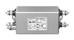
| 描述 | AC 电源线滤波器 2-LEITER EMV-FILTER 20A 250V |
| 产品分类 | 交流电源线路滤波器 |
| 产品手册 | |
| 产品图片 |
|
| rohs | 符合RoHS |
| 产品系列 | EPCOS B84113H0000M120 |
| 产品型号 | B84113H0000M120 |
| 产品种类 | 交流电源线路滤波器 |
| 商标 | EPCOS |
| 安装风格 | Screw |
| 封装 | Bulk |
| 工厂包装数量 | 16 |
| 漏泄电流 | 2 uA |
| 电压额定值 | 250 VAC, 250 VDC |
| 电流额定值 | 20 A |
| 端接类型 | Tab |
| 系列 | B84113H0000* |
| 认证 | ENEC10, UL, cUL |
| 过滤器类型 | 2-line filter |
| 零件号别名 | B84113HM120 |
| 频率 | 50/60 Hz |


- 商务部:美国ITC正式对集成电路等产品启动337调查
- 曝三星4nm工艺存在良率问题 高通将骁龙8 Gen1或转产台积电
- 太阳诱电将投资9.5亿元在常州建新厂生产MLCC 预计2023年完工
- 英特尔发布欧洲新工厂建设计划 深化IDM 2.0 战略
- 台积电先进制程称霸业界 有大客户加持明年业绩稳了
- 达到5530亿美元!SIA预计今年全球半导体销售额将创下新高
- 英特尔拟将自动驾驶子公司Mobileye上市 估值或超500亿美元
- 三星加码芯片和SET,合并消费电子和移动部门,撤换高东真等 CEO
- 三星电子宣布重大人事变动 还合并消费电子和移动部门
- 海关总署:前11个月进口集成电路产品价值2.52万亿元 增长14.8%


PDF Datasheet 数据手册内容提取
EMC filters 2-line filters SIFI-H for very high insertion loss Series/Type: B84113H Date: April 2018 ©EPCOSAG2018.Reproduction,publicationanddisseminationofthispublication,enclosuresheretoandthe informationcontainedthereinwithoutEPCOS'priorexpressconsentisprohibited. EPCOSAGisaTDKGroupCompany.
2-line filters B84113H SIFI-H for very high insertion loss Power line filters for 1-phase systems Rated voltage V : 250 V AC/DC R Rated current I : 3 A to 36 A R Construction 2-line filters Metal case Polyurethane potting (UL 94 V-0) Versions Standard version (B84113H0000B*/G*) For applications with low leakage current (B84113H0000M*) Features Easy to install Compact design Cost optimized construction ENEC, UL and cUL approval Typical applications Switch-mode power supplies Industrial electronics Telecom systems Data systems DC applications Medical equipment (version B84113H0000M*) Terminals 3 A ... 16 A: Tab connectors 20 A ... 36 A: Threaded studs Marking Marking on component: Manufacturer's logo, ordering code, rated voltage, rated current, rated temperature, climatic category, date code, approvals Minimum data on packaging: Manufacturer's logo, ordering code, quantity, date code PleasereadCautionsandwarningsand Page2of15 Importantnotesattheendofthisdocument.
2-line filters B84113H SIFI-H for very high insertion loss Typical circuit diagram (standard version) Typical circuit diagram (medical version) Technical data and measuring conditions Rated voltage V 250 V AC (50/60 Hz) / 250 V DC R Rated current I Referred to 40 °C rated temperature R Test voltage V 1770 V DC, 2 s (line/line) test Standard version: 2700 V DC, 2 s (lines/case) Medical version: 2500 V AC, 2 s (lines/case) Leakage current l At V and 50 Hz LK R Climatic category (IEC 60068-1) 25/100/21 ((cid:4)25 °C/+100 °C/21 days damp heat test) Approvals IEC 60939, UL 1283, CSA C22.2 No.8 PleasereadCautionsandwarningsand Page3of15 Importantnotesattheendofthisdocument.
2-line filters B84113H SIFI-H for very high insertion loss Characteristics and ordering codes I C C L I Approx. Ordering code Approvals R R R R LK X2 Y2 weight A μF pF mH mA g V = 250 V AC/DC R 3 2 × 1.0 2 × 4700 4 × 5.9 0.369 250 B84113H0000B030 × × × 3 2 × 1.0 (cid:4) 4 × 5.9 0 250 B84113H0000M030 × × × 6 2 × 1.0 2 × 4700 4 × 3.6 0.369 260 B84113H0000B060 × × × 6 2 × 1.0 (cid:4) 4 × 3.6 0 260 B84113H0000M060 × × × 10 2 × 1.5 2 × 4700 4 × 3.9 0.369 420 B84113H0000B110 × × × 10 2 × 1.5 (cid:4) 4 × 3.9 0 420 B84113H0000M110 × × × 16 2 × 1.5 2 × 4700 4 × 1.3 0.369 440 B84113H0000B116 × × × 16 2 × 1.5 (cid:4) 4 × 1.3 0 440 B84113H0000M116 × × × 20 2 × 2.2 2 × 22000 4 × 1.2 1.73 860 B84113H0000G120 × × × 20 2 × 2.2 (cid:4) 4 × 1.2 0 860 B84113H0000M120 × × × 25 2 × 2.2 2 × 22000 4 × 0.8 1.73 870 B84113H0000G125 × × × 25 2 × 2.2 (cid:4) 4 × 0.8 0 870 B84113H0000M125 × × × 36 2 × 3.3 2 × 22000 4 × 0.5 1.73 870 B84113H0000G136 × × × 36 2 × 3.3 (cid:4) 4 × 0.5 0 870 B84113H0000M136 × × × × = Approval granted Dimensional drawings B84113H0000*030, B84113H0000*060 (3 A, 6 A) General tolerances according to ISO 2768(cid:4)cL Dimensions in mm PleasereadCautionsandwarningsand Page4of15 Importantnotesattheendofthisdocument.
2-line filters B84113H SIFI-H for very high insertion loss B84113H0000*110, B84113H0000*116 (10 A, 16 A) General tolerances according to ISO 2768(cid:4)cL Dimensions in mm B84113H0000*120 ... B84113H0000*136 (20 A ... 36 A) General tolerances according to ISO 2768(cid:4)cL Dimensions in mm PleasereadCautionsandwarningsand Page5of15 Importantnotesattheendofthisdocument.
2-line filters B84113H SIFI-H for very high insertion loss Insertion loss for standard version (typical values at Z = 50 Ω) Filters for 3 A Filters for 6 A Filters for 10 A Filters for 16 A PleasereadCautionsandwarningsand Page6of15 Importantnotesattheendofthisdocument.
2-line filters B84113H SIFI-H for very high insertion loss Insertion loss for standard version (typical values at Z = 50 Ω) Filters for 20 A Filters for 25 A Filters for 36 A PleasereadCautionsandwarningsand Page7of15 Importantnotesattheendofthisdocument.
2-line filters B84113H SIFI-H for very high insertion loss Insertion loss for medical version (typical values at Z = 50 Ω) Filters for 3 A Filters for 6 A Filters for 10 A Filters for 16 A PleasereadCautionsandwarningsand Page8of15 Importantnotesattheendofthisdocument.
2-line filters B84113H SIFI-H for very high insertion loss Insertion loss for medical version (typical values at Z = 50 Ω) Filters for 20 A Filters for 25 A Filters for 36 A PleasereadCautionsandwarningsand Page9of15 Importantnotesattheendofthisdocument.
2-line filters B84113H SIFI-H for very high insertion loss Cautions and warnings Please read all safety and warning notes carefully before installing the filter and putting it into op- eration (see ). The same applies to the warning signs on the filter. Please ensure that the signs are not removed nor their legibility impaired by external influences. Death, serious bodily injury and substantial material damage to equipment may occur if the appro- priate safety measures are not carried out or the warnings in the text are not observed. Using according to the terms The filters may be used only for their intended application within the specified values in low- voltage networks in compliance with the instructions given in the data sheets and the data book. The conditions at the place of application must comply with all specifications for the filter used. Warning It shall be ensured that only qualified persons (electricity specialists) are engaged on work such as planning, assembly, installation, operation, repair and maintenance. They must be provided with the corresponding documentation. Danger of electric shock. Filters contain components that store an electric charge. Dangerous voltages can continue to exist at the filter terminals for longer than five minutes even after the power has been switched off. The protective earth connections shall be the first to be made when the filter is installed and the last to be disconnected. Depending on the magnitude of the leakage currents, the particular specifications for making the protective earth connection must be observed. Impermissible overloading of the filter or filter, such as with circuits able to cause resonances, impermissible voltages at higher frequencies etc. can lead to bodily injury and death as well as cause substantial material damages (e.g. destruction of the filter housing). Filters must be protected in the application against impermissible exceeding of the rated cur- rents by overcurrent protective devices. In case of leakage currents >3.5 mA you shall mount the PE conductor stationary with the re- quired cross section before beginning of operation and save it against disconnecting. For leak- age currents I 1) ≤10 mA the PE conductor must have a KU value2) of 4.53); for leakage currents L I >10 mA the PE conductor must have a KU value of 64). L Output chokes and output filters must be protected in the application against impermissible ex- ceeding of the component temperature. The converter output frequency must be within the specified range to avoid resonances and un- controlled warming of the output chokes and output filters. Because the product can become very hot during operation, there is the risk of burns if touched. The product can remain hot for some time after the power is switched off! 1) I =leakagecurrentlet-go L 2) TheKUvalue(symbolKU)isaclassificationparameterofsafety-referredfailuretypesdesignedtoensureprotectionagainsthazardous bodycurrentsandexcessiveheating. 3) AvalueofKU=4.5withrespecttointerruptionsisattainedwith:a)permanentlyconnectedprotectiveearthconnection≥1.5mm2and b)aprotectiveearthconnection≥2.5mm2viaconnectorsforindustrialequipment(IEC60309(cid:4)2) 4) KU=6withrespecttointerruptionsisachievedforfixed-connectionlines≥10mm2wherethetypeofconnectionandinstallationcorre- spondtotherequirementsforPENconductorsasspecifiedinrelevantstandards. PleasereadCautionsandwarningsand Page10of15 Importantnotesattheendofthisdocument.
2-line filters B84113H SIFI-H for very high insertion loss The table below summarizes the safety instructions that must be observed without fail. A detailed description can be found in the relevant chapters of the databook. Topic Instructions Reference chapter (data book), paragraph Selecting a filter When selecting a filter, it is mandatory to observe the Selection guide for rated data of the equipment (such as its rated input converter filters current, rated voltage, harmonic content etc.) as well as the derating instructions in Chapters 9 and 10. Rated voltage When power distribution systems deviating from the Power distribution symmetric TN-S system is to check the suitability of systems, the filters and the allowed voltages including the fault 7 cases. Protection from Active parts must be discharged within 5 s to a Safety regulations, residual voltages voltage of less than 60 V (or 50 μ C). If this limit 6.1 Discharge resistors cannot be observed due to the operating mode, the hazardous point must be permanently marked in a clearly visible way. Filters which are not permanently connected (e.g. Safety regulations, when the test voltage is applied to the filter at the 6.2 incoming goods inspection) must be discharged after the voltage has been switched off. Installing and When installing and removing our filters, a Safety regulations, removing of filters voltage-free state must be set up and secured with 6.4 observance of the five safety rules described in Installation EN 50110-1. Use in IT systems The special features of the IT system ("first fault case" Power distribution and other fault cases) shall be observed. system (network types), 7.6 Safety notes on The filter leakage currents specified in the data book Leakage current, leakage currents are intended for user information only.The maximum 8.4 leakage current of the entire electrical equipment or Leakage current, appliance has to be limited for safety reasons. Please 8.6 obtain the applicable limits for your application from the relevant regulations, provisions and standards. Voltage derating If the permissible limits for the higher-frequency Voltage derating, voltages at the filter are exeeded, the filter may be 9.8 Hazards caused by damaged or destroyed. overloading the filters Current derating at Non-observance of the current derating may lead to Current derating, elevated ambient overheating and consequently represents a fire 10.1 temperatures hazard. PleasereadCautionsandwarningsand Page11of15 Importantnotesattheendofthisdocument.
2-line filters B84113H SIFI-H for very high insertion loss Topic Instructions Reference chapter (data book), paragraph Protective earth For operating currents greater than 250 A, we Mounting connection at recommend the PE connection to be set up between instructions, operating currents the feed (filter: line) and output (filter: load) not via the point 2 >250 A PE terminal bolt in the filter housing. Mounting position Note the mounting position of the filters! It must Mounting always be ensured that natural convection is not instructions, impaired. point 13 Long motor cables Long motor cables cause parasitic currents in the Mounting installation. The cable lengths indicated for the output instructions, chokes and output filters serve for orientation. The point 15 user must check the technical parameters and especially the choke temperatures for the respective application. Display of ordering codes for EPCOS products The ordering code for one and the same product can be represented differently in data sheets, data books, other publications and the website of EPCOS, or in order-related documents such as shipping notes, order confirmations and product labels. The varying representations of the order- ing codes are due to different processes employed and do not affect the specifications of the re- spective products. Detailed information can be found on the Internet under www.epcos.com/orderingcodes. PleasereadCautionsandwarningsand Page12of15 Importantnotesattheendofthisdocument.
2-line filters B84113H SIFI-H for very high insertion loss Symbols and terms Symbol English German α Insertion loss Einfügungsdämpfung C Rated capacitance Bemessungskapazität R C Capacitance X capacitor Kapazität X-Kondensator X C Capacitance Y capacitor Kapazität Y-Kondensator Y ΔV Voltage drop (input to output) Spannungsabfall im Filter dv/dt Rate of voltage rise Spannungsanstiegsgeschwindigkeit f Frequency Frequenz f Converter output frequency Motorfrequenz M f Pulse frequency Pulsfrequenz P f Rated frequency Bemessungsfrequenz R f Resonant frequency Resonanzfrequenz res I Current through capacitor Strom durch Kondensator C I Filter leakage current Filter-Ableitstrom LK I Maximum current Maximalstrom max I Nominal current Nennstrom N I Operating current (design current) Betriebsstrom op I Rated peak withstand current Bemessungs-Stoßstromfestigkeit pk I Capacitive reactive current Kapazitiver Blindstrom q I Rated current Bemessungsstrom R I Interference current Störstrom S L Inductance Induktivität L Rated inductance Bemessungsinduktivität R L Stray inductance Streuinduktivität stray P Power loss Verlustleistung L R Resistance Widerstand R Insulation resistance Isolationswiderstand is R DC resistance, typical value Gleichstromwiderstand, Richtwert typ T Ambient temperature Umgebungstemperatur A T Upper category temperature Obere Kategorietemperatur max T Lower category temperature Untere Kategorietemperatur min T Rated temperature Bemessungstemperatur R u Refered voltage drop in % Bezogener Spannungsabfall in % k V RMS voltage Effektivspannung eff V Voltage drop Spannungsabfall K V Voltage line to earth; voltage line to ground Spannung Phase zu Erdpotential LE V Nominal voltage Nennspannung N V Rated voltage Bemessungsspannung R V Peak voltage Spitzenspannung peak V Test voltage Prüfspannung test V Voltage over X capacitor Spannung über X-Kondensator X V Voltage over Y capacitor Spannung über Y-Kondensator Y X Inductive reactance Induktiver Blindwiderstand L Z Impedance Scheinwidertand |Z| Impedance, absolute value Scheinwiderstand (Betragswert) PleasereadCautionsandwarningsand Page13of15 Importantnotesattheendofthisdocument.
Important notes The following applies to all products named in this publication: 1. Some parts of this publication contain statements about the suitability of our products for certain areas of application. These statements are based on our knowledge of typical re- quirements that are often placed on our products in the areas of application concerned. We nevertheless expressly point out that such statements cannot be regarded as binding statements about the suitability of our products for a particular customer application. As a rule, EPCOS is either unfamiliar with individual customer applications or less familiar with them than the customers themselves. For these reasons, it is always ultimately incum- bent on the customer to check and decide whether an EPCOS product with the properties de- scribed in the product specification is suitable for use in a particular customer application. 2. We also point out that in individual cases, a malfunction of electronic components or failure before the end of their usual service life cannot be completely ruled out in the current state of the art, even if they are operated as specified. In customer applications requiring a very high level of operational safety and especially in customer applications in which the malfunction or failure of an electronic component could endanger human life or health (e.g. in accident prevention or lifesaving systems), it must therefore be ensured by means of suitable design of the customer application or other action taken by the customer (e.g. installation of protective circuitry or redundancy) that no injury or damage is sustained by third parties in the event of malfunction or failure of an electronic component. 3. The warnings, cautions and product-specific notes must be observed. 4. In order to satisfy certain technical requirements, some of the products described in this publication may contain substances subject to restrictions in certain jurisdictions (e.g. because they are classed as hazardous). Useful information on this will be found in our Ma- terial Data Sheets on the Internet (www.epcos.com/material). Should you have any more de- tailed questions, please contact our sales offices. 5. We constantly strive to improve our products. Consequently, the products described in this publication may change from time to time. The same is true of the corresponding product specifications. Please check therefore to what extent product descriptions and specifications contained in this publication are still applicable before or when you place an order. We also reserve the right to discontinue production and delivery of products. Consequently, we cannot guarantee that all products named in this publication will always be available. The aforementioned does not apply in the case of individual agreements deviating from the fore- going for customer-specific products. 6. Unless otherwise agreed in individual contracts, all orders are subject to the current ver- sion of the "General Terms of Delivery for Products and Services in the Electrical In- dustry" published by the German Electrical and Electronics Industry Association (ZVEI). Page14of15
Important notes 7. The trade names EPCOS, CeraCharge, CeraDiode, CeraLink, CeraPad, CeraPlas, CSMP, CTVS, DeltaCap, DigiSiMic, ExoCore, FilterCap, FormFit, LeaXield, MiniBlue, MiniCell, MKD, MKK, MotorCap, PCC, PhaseCap, PhaseCube, PhaseMod, PhiCap, PowerHap, PQSine, PQvar, SIFERRIT, SIFI, SIKOREL, SilverCap, SIMDAD, SiMic, SIMID, SineFormer, SIOV, ThermoFuse, WindCap are trademarks registered or pending in Europe and in other coun- tries. Further information will be found on the Internet at www.epcos.com/trademarks. Page15of15
Mouser Electronics Authorized Distributor Click to View Pricing, Inventory, Delivery & Lifecycle Information: E PCOS / TDK: B84113H0000B110 B84113H0000B116 B84113H0000G120 B84113H0000B030 B84113H0000B060 B84113H0000M030 B84113H0000M060 B84113H0000M110 B84113H0000M116 B84113H0000M120 B84113H0000M125 B84113H0000M136 B84113H0000G125 B84113H0000G136