ICGOO在线商城 > ZW50F92AW1-Z

 Datasheet下载
- 型号: ZW50F92AW1-Z
- 制造商: Honeywell Solid State Electronics
- 库位|库存: xxxx|xxxx
- 要求:
| 数量阶梯 | 香港交货 | 国内含税 |
| +xxxx | $xxxx | ¥xxxx |
查看当月历史价格
查看今年历史价格
ZW50F92AW1-Z产品简介:
ICGOO电子元器件商城为您提供ZW50F92AW1-Z由Honeywell Solid State Electronics设计生产,在icgoo商城现货销售,并且可以通过原厂、代理商等渠道进行代购。 提供ZW50F92AW1-Z价格参考以及Honeywell Solid State ElectronicsZW50F92AW1-Z封装/规格参数等产品信息。 你可以下载ZW50F92AW1-Z参考资料、Datasheet数据手册功能说明书, 资料中有ZW50F92AW1-Z详细功能的应用电路图电压和使用方法及教程。
| 参数 | 数值 |
| IP等级 | IP 67 |
| 品牌 | Honeywell |
| 产品目录 | 机电产品 |
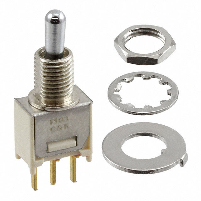
| 描述 | 基本/快动开关 SPDT, 5A 125/250VAC IP67,CBL SIDE EXIT |
| 产品分类 | |
| 产品手册 | http://sensing.honeywell.com/index.php?ci_id=151138 |
| 产品图片 |
|
| rohs | 符合RoHS |
| 产品系列 | 基本/快动开关,Honeywell ZW50F92AW1-Z |
| mouser_ship_limit | 该产品可能需要其他文件才能进口到中国。 |
| 产品型号 | ZW50F92AW1-Z |
| 产品种类 | 基本/快动开关 |
| 商标 | Honeywell |
| 安装 | Panel |
| 工作力 | 0.5 N |
| 开关功能 | ON - (OFF), OFF - (ON) |
| 执行器 | Plunger, Pin |
| 电压额定值AC | 125 V, 250 V |
| 电压额定值DC | - |
| 电流额定值 | 5 A |
| 端接类型 | Wire Leads |
| 类型 | Miniature |
| 系列 | Z |
| 触点形式 | SPDT |


- 商务部:美国ITC正式对集成电路等产品启动337调查
- 曝三星4nm工艺存在良率问题 高通将骁龙8 Gen1或转产台积电
- 太阳诱电将投资9.5亿元在常州建新厂生产MLCC 预计2023年完工
- 英特尔发布欧洲新工厂建设计划 深化IDM 2.0 战略
- 台积电先进制程称霸业界 有大客户加持明年业绩稳了
- 达到5530亿美元!SIA预计今年全球半导体销售额将创下新高
- 英特尔拟将自动驾驶子公司Mobileye上市 估值或超500亿美元
- 三星加码芯片和SET,合并消费电子和移动部门,撤换高东真等 CEO
- 三星电子宣布重大人事变动 还合并消费电子和移动部门
- 海关总署:前11个月进口集成电路产品价值2.52万亿元 增长14.8%


PDF Datasheet 数据手册内容提取
MICRO SWITCH™ Sealed Subminiature Basic Switches ZW Series Datasheet
MICRO SWITCH™ ZW Series Sealed Subminiature Basic Switches Honeywell’s MICRO SWITCH™ ZW Series is a sealed subminiature snap action switch from the Honeywell family of Z Series subminiature basic switches. Although small in size, the ZW Series is rated for controlling electrical loads ranging from logic level/computer-based circuits to power-duty switching (up to 6 amps and up to 250 Vac). Switches supplied with integral wire leads are sealed to IP67 and are suitable for applications where a switch assembly would be exposed to liquids or particulate contaminates in the environment from indoor or outdoor use. A wide variety of stainless steel levers are available and when combined with the subminiature package size, can adapt the switch for many different applications. The ZW Series is certified to UL, cUL, ENEC, and CQC for worldwide use. What makes our switches better? The IP67-rated sealed switch is designed to operate in a variety of demanding applications, reducing the challenge of harsh environments Wide variety of electrical current carrying capacity allows for a solution in many systems Switch package designed to accommodate a wide range of temperature requirements For worldwide use... RIGHT SWITCH FOR THE RIGHT APPLICATION HARSH ENVIRONMENTS • RELIABILITY • ELECTRICAL RATING 2 sensing.honeywell.com
FFeeaattuurreess SMALL PACKAGE SIZE aanndd BBeenneefifittss Subminiature package size allows the MICRO SWITCH™ ZW Series switch to fit in many applications where other sensors or switches are too large. IP67 sealing: pre-wired switches WELL SUITED FOR POWER-DUTY AND LOGIC-LEVEL LOADS SPDT, SPNC, or SPNO switch options are available and designed to meet various circuit requirements. ZW Series can control power-duty switching with silver contacts or logic-level computer-based circuits with gold-plated contacts. PERFORMS IN WET, DIRTY, AND DUSTY ENVIRONMENTS Catalog listings with integral lead wires are sealed to IP67 for use in environments where exposure to liquid ingress or particulate contaminant could occur. DESIGN FLEXIBILITY Switches are built with an integral sealed pin plunger. Various styles of levers expand the versatility of the ZW Series switch in the application. In addition, the ZW Series features a variety of terminations to promote flexibility for the electrical connectivity. Potential Applications LAWN TRACTORS Reverse alarm for lawn tractors Indicates seat use on lawn tractors WATERCRAFT Found on handle-bar controls for personal watercraft (wave runners) SECURITY SYSTEMS Acts as an interlock for security system panel SNOWMOBILES Found on handle-bar controls for snowmobiles sensing.honeywell.com 3
ZW Series PRODUCT NOMENCLATURE ZW 50 F 15 A D 1 — Current Operating Force4 Terminal Actuator Type3 Special Switch Type Rating (at pin plunger) Type (Levers Mounted Internally) Construction Circuitry Designator3 ZWSe Saelerdies 10 0(cG.o1onAltda 1-cp2tsl5a)/t2e5d0 Vac E 150 g max. 15 Solder A Pin plunger D IDPu0s0t tight 1 SPDT a Aniso s nup-sesetcadian tld oda ierndsd igficenaaatteuto rer, SubBmainsiiacture 506(SAil:v 1e2r 5c/o2n5t0a cVtasc) ONLY F 203 g max. 20 PCB, straight B Slehvoerrt (s1t7ra,4ig mhtm) W IWPa6t7er tight 3 SPNO 2 wiarescu tluecanhtg oatrsh, ,wa ci rsoepn cenocelicoatrlo, r, Switch 70 L2[0o,8.n1 gm1 msino xlxd 00e,.r50 2m inm] C Sletvaenrd (a1r9d, 4s tmramig)ht 4 SPNC 2 conseaitslcpt.sh Taohnf iusum pc eotordi cethree 90 Cexaibt le(5,0 0b momtto)m D Lleovnegr (s2t5ra,5ig mhtm) characters. (UL10007 Dia 1.0)4,5 91 C(Oappbolseit,e spilduneg eer)xit E Sleivmeur la(1te8d,7 r mollmer; (500 mm) (UL1007 Dia)4,5 R 3,4 mm) 92 C(Plaunbgleer, e snidd)e exit F R(1o7ll,e2r mlemve; r (500 mm) (UL1007 Dia)4,5 Ø 4,8 mm) 99 SPECIAL3 H Sromllearl l lesivmeur lated (18,6 mm; R1,3 mm) J Long straight lever (55,9 mm) S SPECIAL Lever2 NOTES: 1 Not all combinations of model code are available. Please contact your Honeywell provider/representative for assistance. 2 Termination style “99” and/or Actuator Type “S” designates a special and therefore requires a special designator letter at the end of the listing 3 Lever length is measured as follows: Straight lever - from center line of the pivot to the end of the lever; Roller and simulated roller lever - from the center line of the pivot to the center of the roller diameter. See page 8 for more details. 4 Standard wire length is 500 mm [19.68 in] long. Other lengths are available upon request. Lead wire with end stripped 3,0 mm [0.118 in] and pre-tinned. COM: black; NC: gray; NO: blue 5 Standard lead wire is UL1007 20 AWG cable. Other lead wire types, such as UL1015, UL1430, UL1061, and AVSS are available upon request. - 4 sensing.honeywell.com
MICRO SWITCH™ Sealed Subminiature Basic Switches Table 1. Specifications Characteristic ZW10 Series (Logic Level) ZW50 Series (Power Duty) Circuitry SPDT, SPNC, SPNO SPDT, SPNC, SPNO Operating force 150 g or 203 g @ plunger 150 g or 203 g @ plunger Termination PCB, solder, prewired PCB, solder, prewired Sealing IP67 (prewired), IP00 for exposed terminals IP67 (prewired), IP00 for exposed terminals Actuators (levers 300 series pin plunger, flat lever, roller lever, sim. roller lever, pin plunger, flat lever, roller lever, sim. roller lever, stainless steel) special levers special levers Agency certification UL, cUL, ENEC, CQC, RoHS compliant UL, cUL, ENEC, CQC, RoHS compliant Operating temperature -40 °C to 120 °C [-40 °F to 248 °F] (terminal) -40 °C to 120 °C [-40 °F to 248 °F] (terminal) (Manufacturer rated) -20 °C to 70 °C [-4 °F to 158 °F] (pre-wired) -20 °C to 70 °C [-4 °F to 158 °F] (pre-wired) Mechanical endurance (cycles) 1,000,000 min. @ 120 cycles/minute max. 1,000,000 min. @ 120 cycles/minute max. Switch resistance (initial) 50 mΩ max. (terminals); 100 mΩ max (pre-wired) 50 mΩ max. (terminals); 100 mΩ max (pre-wired) Insulation resistance (initial) 100 MΩ min. (500 Vdc for one minute) 100 MΩ min. (500 Vdc for one minute) Dielectric strength (initial) 1500 VRMS for one minute 1500 VRMS for one minute (between live parts and ground) <0.5 mA leakage current <0.5 mA leakage current Plunger seal silicone silicone Contact material gold-plated silver silver Housing material case, PBT (polyester); cover, PBT (polyester) case, PBT (polyester); cover, PBT (polyester) Note: Refer to engineering drawing for additional information. Table 2. Electrical Ratings CQC (Asia-Pacific) ENEC (Europe) UL, cUL (Americas) Switch option Per GB 15092-1 Per IEC 61058-1 UL 61058-1, File 12252 ZW10 Series 0.1 A, 125/250 Vac 0.1 A, 250 Vac 0.1 RA, 125/250 Vac (Gold-plated contacts) 10,000 cycles 10,000 cycles 10,000 cycles ZW50 Series 6 A, 125/250 Vac 6 A, 250 Vac 5 RA, 125/250 Vac (Silver contacts) 10,000 cycles 10,000 cycles 10,000 cycles Note: The agency “use temperature” for solder or PCB terminals: 0 °C to 120 °C [32 °F to 248 °F]; CQC/ENEC “use temperature” for wire leads: 0 °C to 70 °C [32 °F to 158 °F]. UL/cUL “use temperature” for wire leads: 0 °C to 55 °C [32 °F to 131 °F]. sensing.honeywell.com 5
ZW Series O.F. • Operating force R.F. • Release force P.T. • Pretravel PRODUCT SPECIFICATIONS AND LISTINGS O.T. • Overtravel D.T. • Differential travel Contact your Honeywell rep or distributor for additional listings O.P. • Operating position Circuitry/ Elect. O.P. from mounting O.P. from base of Rating O.F. max. R.F. max. hole terminal Catalog Listing Actuator Contact Termination P.T. max. O.T. min. D.T. max. Spec. N [g] N [g] mm [in] mm [in] Material (page 5) (see page 8) (see page 8) SPDT/ 11,5 ±0,3 ZW10F20AD1 Pin plunger 0.1 A PCB 2,00 N [203 g] 0,49 N [50 g] – 1,2 mm [0.05 in] 0,6 mm [0.02 in] 0,2 mm [0.01 in] Gold plate [0.45 ±0.012] SPDT/ Wire leads, bottom exit 8,4 ±0,3 ZW10F90AW1 Pin plunger 0.1 A 2,00 N [203 g] 0,49 N [50 g] – 1,2 mm [0.05 in] 0,6 mm [0.02 in] 0,2 mm [0.01 in] Gold plate (500 mm) [0.33 ±0.012] SPDT/ 8,4 ±0,3 ZW50F15AD1 Pin plunger 6 A Solder 2,00 N [203 g] 0,49 N [50 g] – 1,2 mm [0.05 in] 0,6 mm [0.02 in] 0,2 mm [0.01 in] Silver [0.33 ±0.012] SPDT/ Wire leads, bottom exit 8,4 ±0,3 ZW50F90AW1 Pin plunger 6 A 2,00 N [203 g] 0,49 N [50 g] – 1,2 mm [0.05 in] 0,6 mm [0.02 in] 0,2 mm [0.01 in] Pin plunger Silver (500 mm) [0.33 ±0.012] SPNO/ Wire leads, side exit, 8,4 ±0,3 ZW50F92AW3 Pin plunger 6 A 2,00 N [203 g] 0,49 N [50 g] – 1,2 mm [0.05 in] 0,6 mm [0.02 in] 0,2 mm [0.01 in] Silver plunger side (500 mm) [0.33 ±0.012] Standard straight lever, SPDT/ 8,8 ±1,2 ZW10E15CD1 0.1 A Solder 0,54 N [55 g] 0,11 N [11 g] – 4,8 mm [0.19 in] 1,0 mm [0.04 in] 0,7 mm [0.03 in] 19,4 mm [0.76 in] Gold plate [0.35 ±0.047] Standard straight lever, SPNO/ Wire leads, bottom exit 8,8 ±1,2 ZW50F90CW3 6 A 0,65 N [66 g] 0,13 N [13 g] – 4,8 mm [0.19 in] 1,0 mm [0.04 in] 0,7 mm [0.03 in] 19,4 mm [0.76 in] Silver (500 mm) [0.35 ±0.047] Standard straight lever, SPNO/ Wire leads, side exit, 8,8 ±1,2 ZW50F92CW3 6 A 0,65 N [66] g 0,13 N [13 g] – 4,8 mm [0.19 in] 1,0 mm [0.04 in] 0,7 mm [0.03 in] Std. straight lever 19,4 mm [0.76 in] Silver plunger side (500 mm) [0.35 ±0.047] Long straight lever, SPDT/ Wire leads, bottom exit 8,8 ±1,6 ZW50F90DW1 6 A 0,53 N [54 g] 0,11 N [11 g] – 6,3 mm [0.25 in] 1,6 mm [0.06 in] 0,9 mm [0.04 in] 25,5 mm [1.0 in] Silver (500 mm) [0.35 ±0.063] Longer straight lever, SPDT/ Wire leads, bottom exit 8,8 ±3,5 ZW50F90JW1 6 A 0,32 N [33 g] 0,07 N [7 g] – 13,8 mm [0.54 in] 2,9 mm [0.11 in] 3,60 mm [0.14 in] 52,9 mm [2.20 in] Silver (500 mm) [0.34 ±0.138] Long straight lever Sim. roller lever, SPNO/ Wire leads, bottom exit 11,7 ±1,15 ZW50F90EW3 18,65 mm [0.73 in] 6 A 0,68 N [69 g] 0,13 N [13 g] – 4,7 mm [0.18 in] 0,9 mm [0.04 in] 0,75 mm [0.03 in] Silver (500 mm) [0.46 ±0.045] radius: 3,4 mm [0.13 in] Sim. roller lever Small radius, sim. roller lever, SPDT/ Wire leads, bottom exit 10,7 ±1,2 ZW50F90HW1 18,6 mm [0.73 in] 6 A 0,67 N [68 g] 0,14 N [14 g] – 4,6 mm [0.18 in] 1,0 mm [0.04 in] 0,75 mm [0.03 in] Silver (500 mm) [0.42 ±0.047] radius: 1,3 mm [0.05 in] Small radius, sim. roller lever, Wire leads, side exit, SPDT/ 10,7 ±1,2 ZW50F91HW1 18,6 mm [0.73 in] 6 A opposite plunger 0,67 N [68 g] 0,14 N [14 g] – 4,6 mm [0.18 in] 1,0 mm [0.04 in] 0,75 mm [0.03 in] Silver [0.42 ±0.047] Sim. roller lever radius: 1,3 mm [0.05 in] (500 mm) Roller lever, SPDT/ 14,5 ±1,1 ZW10E70FD1 0.1 A Solder (long terminal) 0,59 N [60 g] 0,12 N [12 g] – 4,3 mm [0.17 in] 0,9 mm [0.04 in] 0,6 mm [0.02 in] 17,2 mm [0.68 in] Gold plate [0.57 ±0.043] Roller lever SPDT/ Wire leads, bottom exit 14,5 ±1,1 ZW10E90FW1 0.1 A 0,59 N [60 g] 0,12 N [12 g] – 4,3 mm [0.17 in] 0,9 mm [0.04 in] 0,6 mm [0.02 in] 17,2 mm [0.68 in] Gold plate (500 mm) [0.57 ±0.043] Roller lever SPDT/ Wire leads, bottom exit 14,5 ±1.1 ZW50F90FW1 6 A 0,71 N [72 g] 0,15 N [15 g] – 4,3 mm [0.17 in] 0,9 mm [0.04 in] 0,6 mm [0.02 in] Roller lever 17,2 mm [0.68 in] Silver (500 mm) [0.57 ±0.043] 6 sensing.honeywell.com
MICRO SWITCH™ Sealed Subminiature Basic Switches O.F. • Operating force R.F. • Release force P.T. • Pretravel O.T. • Overtravel D.T. • Differential travel O.P. • Operating position Circuitry/ Elect. O.P. from mounting O.P. from base of Rating O.F. max. R.F. max. hole terminal Catalog Listing Actuator Contact Termination P.T. max. O.T. min. D.T. max. Spec. N [g] N [g] mm [in] mm [in] Material (page 5) (see page 8) (see page 8) SPDT/ 11,5 ±0,3 ZW10F20AD1 Pin plunger 0.1 A PCB 2,00 N [203 g] 0,49 N [50 g] – 1,2 mm [0.05 in] 0,6 mm [0.02 in] 0,2 mm [0.01 in] Gold plate [0.45 ±0.012] SPDT/ Wire leads, bottom exit 8,4 ±0,3 ZW10F90AW1 Pin plunger 0.1 A 2,00 N [203 g] 0,49 N [50 g] – 1,2 mm [0.05 in] 0,6 mm [0.02 in] 0,2 mm [0.01 in] Gold plate (500 mm) [0.33 ±0.012] SPDT/ 8,4 ±0,3 ZW50F15AD1 Pin plunger 6 A Solder 2,00 N [203 g] 0,49 N [50 g] – 1,2 mm [0.05 in] 0,6 mm [0.02 in] 0,2 mm [0.01 in] Silver [0.33 ±0.012] SPDT/ Wire leads, bottom exit 8,4 ±0,3 ZW50F90AW1 Pin plunger 6 A 2,00 N [203 g] 0,49 N [50 g] – 1,2 mm [0.05 in] 0,6 mm [0.02 in] 0,2 mm [0.01 in] Pin plunger Silver (500 mm) [0.33 ±0.012] SPNO/ Wire leads, side exit, 8,4 ±0,3 ZW50F92AW3 Pin plunger 6 A 2,00 N [203 g] 0,49 N [50 g] – 1,2 mm [0.05 in] 0,6 mm [0.02 in] 0,2 mm [0.01 in] Silver plunger side (500 mm) [0.33 ±0.012] Standard straight lever, SPDT/ 8,8 ±1,2 ZW10E15CD1 0.1 A Solder 0,54 N [55 g] 0,11 N [11 g] – 4,8 mm [0.19 in] 1,0 mm [0.04 in] 0,7 mm [0.03 in] 19,4 mm [0.76 in] Gold plate [0.35 ±0.047] Standard straight lever, SPNO/ Wire leads, bottom exit 8,8 ±1,2 ZW50F90CW3 6 A 0,65 N [66 g] 0,13 N [13 g] – 4,8 mm [0.19 in] 1,0 mm [0.04 in] 0,7 mm [0.03 in] 19,4 mm [0.76 in] Silver (500 mm) [0.35 ±0.047] Standard straight lever, SPNO/ Wire leads, side exit, 8,8 ±1,2 ZW50F92CW3 6 A 0,65 N [66] g 0,13 N [13 g] – 4,8 mm [0.19 in] 1,0 mm [0.04 in] 0,7 mm [0.03 in] Std. straight lever 19,4 mm [0.76 in] Silver plunger side (500 mm) [0.35 ±0.047] Long straight lever, SPDT/ Wire leads, bottom exit 8,8 ±1,6 ZW50F90DW1 6 A 0,53 N [54 g] 0,11 N [11 g] – 6,3 mm [0.25 in] 1,6 mm [0.06 in] 0,9 mm [0.04 in] 25,5 mm [1.0 in] Silver (500 mm) [0.35 ±0.063] Longer straight lever, SPDT/ Wire leads, bottom exit 8,8 ±3,5 ZW50F90JW1 6 A 0,32 N [33 g] 0,07 N [7 g] – 13,8 mm [0.54 in] 2,9 mm [0.11 in] 3,60 mm [0.14 in] 52,9 mm [2.20 in] Silver (500 mm) [0.34 ±0.138] Long straight lever Sim. roller lever, SPNO/ Wire leads, bottom exit 11,7 ±1,15 ZW50F90EW3 18,65 mm [0.73 in] 6 A 0,68 N [69 g] 0,13 N [13 g] – 4,7 mm [0.18 in] 0,9 mm [0.04 in] 0,75 mm [0.03 in] Silver (500 mm) [0.46 ±0.045] radius: 3,4 mm [0.13 in] Sim. roller lever Small radius, sim. roller lever, SPDT/ Wire leads, bottom exit 10,7 ±1,2 ZW50F90HW1 18,6 mm [0.73 in] 6 A 0,67 N [68 g] 0,14 N [14 g] – 4,6 mm [0.18 in] 1,0 mm [0.04 in] 0,75 mm [0.03 in] Silver (500 mm) [0.42 ±0.047] radius: 1,3 mm [0.05 in] Small radius, sim. roller lever, Wire leads, side exit, SPDT/ 10,7 ±1,2 ZW50F91HW1 18,6 mm [0.73 in] 6 A opposite plunger 0,67 N [68 g] 0,14 N [14 g] – 4,6 mm [0.18 in] 1,0 mm [0.04 in] 0,75 mm [0.03 in] Silver [0.42 ±0.047] Sim. roller lever radius: 1,3 mm [0.05 in] (500 mm) Roller lever, SPDT/ 14,5 ±1,1 ZW10E70FD1 0.1 A Solder (long terminal) 0,59 N [60 g] 0,12 N [12 g] – 4,3 mm [0.17 in] 0,9 mm [0.04 in] 0,6 mm [0.02 in] 17,2 mm [0.68 in] Gold plate [0.57 ±0.043] Roller lever SPDT/ Wire leads, bottom exit 14,5 ±1,1 ZW10E90FW1 0.1 A 0,59 N [60 g] 0,12 N [12 g] – 4,3 mm [0.17 in] 0,9 mm [0.04 in] 0,6 mm [0.02 in] 17,2 mm [0.68 in] Gold plate (500 mm) [0.57 ±0.043] Roller lever SPDT/ Wire leads, bottom exit 14,5 ±1.1 ZW50F90FW1 6 A 0,71 N [72 g] 0,15 N [15 g] – 4,3 mm [0.17 in] 0,9 mm [0.04 in] 0,6 mm [0.02 in] Roller lever 17,2 mm [0.68 in] Silver (500 mm) [0.57 ±0.043] sensing.honeywell.com 7
ZW Series MOUNTING DIMENSIONS MOUNTING DIMENSIONS Ø2,30±0,10 2,35 [0.091 ±0.003] [0.093] 2,30 ±0,10 [0.091 ±0.003] 9,25 [0.364] 2,60±0,10 [0.102 ±0.003] 6,40 [0.252] 5,20 Note: unless otherwise noted, [0.205] 9,50±0,15 a tolerace of ±0,4 mm applies [0.374 ±0.005] to all dimensions. 19,80 [0.780] TERMINAL TYPES TYPE 15 - SOLDER (STRAIGHT) TYPE 20 - PCB (STRAIGHT) TYPE 70 -LONG SOLDER TERMINALS TYPE 90 - CABLE-BOTTOM EXIT PT 0,80 OP [0.031] 3,20 4,10 2,40 [0.126] [0.161] [0.094] 15,40 [0.606] 6,90 [0.272] 2,40 [0.094] 2,40 7,50 7,50 7,50 7,50 [0.094] 7,50 7,50 [0.295] [0.295] [0.295] [0.295] [0.295] [0.295] [00.0,5200±±00,.00502] [Ø0 .017,810] [0.002,05 0± 0±.00,0025] [0.002,05 0± 0±.00,0025] [Ø0.10,4270] 5[1090, 6m8i5n]. A DIRECTION B DIRECTION Ø1,80 2,80 [0.071] [02.1,8100] [0.110] [02.1,8100] Ø0,80 0,60 ±0,05 [0.032] A B [0.024 ±0.002] 3,0 ±1,0 7,50 7,50 (35°) (35°) (35°) [0.118 ±0.039] [0.295] [0.295] NC NO COM (GRAY) (BLUE) (BLACK) TYPE 91 - CABLE-SIDE EXIT TYPE 92 - CABLE-SIDE EXIT [ O P P O S I T E P L U N G E R E N D ] [PLUNGER END] 500 min. 500 min. [19.685] [19.685] 3,0 ±1,0 3,0 ±1,0 [0.118 ±0.039] [0.118 ±0.039] 19,25 [0.758] SPDT 19,25 [0.758] SPDT NC (GRAY) COM (BLACK) 15,40 [0.606] SPST 15,40 [0.606] SPST NO (BLUE) NO (BLUE) COM (BLACK) NC (GRAY) Ø1,80 Ø0,80 Ø0,80 Ø1,80 [0.071] [0.032] [0.032] [0.071] ACTUATOR TYPES (ALL ACTUATORS EXCEPT TYPE A AND F ARE 4.0 WIDE) TYPE A TYPE B TYPE C TYPE D PIN PLUNGER SHORT STRAIGHT LEVER (17.4MM) STANDARD ST RAIGHT LEVER (19.4mm) LONG STRA IGHT LEVER (25.5MM) PT Ø2,15 PT [107.6,4805] PT [109.7,4604] PT [0.085] FP OP OP 6,00 OP 6,00 OP 6,00 [0.236] [0.236] [0.236] 7,50 7,50 4,85 7,50 4,85 7,50 4,85 [0.295] [0.295] [0.191] [0.295] [0.191] [0.295] [0.191] TYPE E TYPE F TYPE H TYPE J SIMULATED ROLLER LEVER (18.7MM,R3.4) ROLLER LEVER (17.2MM, ROLL Ø4.8) SMALL SIMULATED ROLLER LEVER (18.6MM,R1.3) LONGEST STRAIGHT LEVER (55.9MM) PT 5,10 PT R[03[1.01,84.37,06435]4] [Øo.41[1,0887.906,]2707] [0.201] PT R[01.0,3501][108.7,6302] PT 5[25.,29001] OP OP OP OP 6,00 6,00 6,00 6,00 [0.236] [0.236] [0.236] [0.236] 7,50 4,85 7,50 4,85 7,50 4,85 7,50 4,85 [0.295] [0.191] [0.295] [0.191] [0.295] [0.191] [0.295] [0.191] ABOVE ''OP" FROM MOUNTING HOLE 8 sensing.honeywell.com PT FP OP 7,45 [0.293] "OP" FROM TERMINAL (FOR TYPE 20 TERMINAL)
ADDITIONAL INFORMATION WARNING The following associated literature is available on the Honeywell web PERSONAL INJURY site at sensing.honeywell.com: DO NOT USE these products as safety or emergency stop • Product installation instructions devices or in any other application where failure of the • Product range guide product could result in personal injury. • Product nomenclature tree Failure to comply with these instructions could result in • Product application-specific information death or serious injury. – Case study: Stamp of approval, ZW Series – Application note: Sensors and switches for potential HVAC/R WARNING applications MISUSE OF DOCUMENTATION – Application note: Sensors and switches in industrial air • The information presented in this product sheet is for compressors reference only. Do not use this document as a product – Application note: Sensors and switches in sanitary valves installation guide. • Complete installation, operation, and maintenance – Application note: Sensors and switches in valves and flow information is provided in the instructions supplied with meters each product. – Application note: Sensors and switches for potential medical Failure to comply with these instructions could result in applications death or serious injury. – Application note: Sensors and switches for valve monitors and valve indicators WARRANTY/REMEDY – Application note: Watertight switches in transportation Honeywell warrants goods of its manufacture as being free of applications defective materials and faulty workmanship. Honeywell’s standard – Technical bulletin: Applying precision switches product warranty applies unless agreed to otherwise by Honeywell – Technical bulletin: Low energy switch guide in writing; please refer to your order acknowledgement or consult your local sales office for specific warranty details. If warranted goods are returned to Honeywell during the period of coverage, Find out more Honeywell will repair or replace, at its option, without charge those Honeywell serves its customers items it finds defective. The foregoing is buyer’s sole remedy through a worldwide network and is in lieu of all other warranties, expressed or implied, of sales offices, representatives including those of merchantability and fitness for a particu- and distributors. For application lar purpose. In no event shall Honeywell be liable for conse- assistance, current specifications, quential, special, or indirect damages. pricing or name of the nearest Authorized Distributor, contact While we provide application assistance personally, through our your local sales office. literature and the Honeywell website, it is up to the customer to determine the suitability of the product in the application. To learn more about Honeywell’s sensing and switching products, Specifications may change without notice. The information we call +1-815-235-6847 or supply is believed to be accurate and reliable as of this printing. 1-800-537-6945, However, we assume no responsibility for its use. visit sensing.honeywell.com, or e-mail inquiries to info.sc@honeywell.com Sensing and Productivity Solutions Honeywell 1985 Douglas Drive North Golden Valley, MN 55422 004989-2-EN IL50 GLO February 2016 honeywell.com Copyright © 2016 Honeywell International Inc. All rights reserved.
Mouser Electronics Authorized Distributor Click to View Pricing, Inventory, Delivery & Lifecycle Information: H oneywell: ZW50F91AW1-Z ZW50F92AW1-Z ZW10F15CD1-Z ZW50F15AD1-Z ZW50F15CD1-Z ZW50F15FD1-Z ZW50F91CW1-B-Z