
 Datasheet下载
- 型号: YC124-JR-0768RL
- 制造商: YAGEO AMERICA CORPORATION
- 库位|库存: xxxx|xxxx
- 要求:
| 数量阶梯 | 香港交货 | 国内含税 |
| +xxxx | $xxxx | ¥xxxx |
查看当月历史价格
查看今年历史价格
YC124-JR-0768RL产品简介:
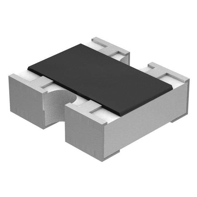
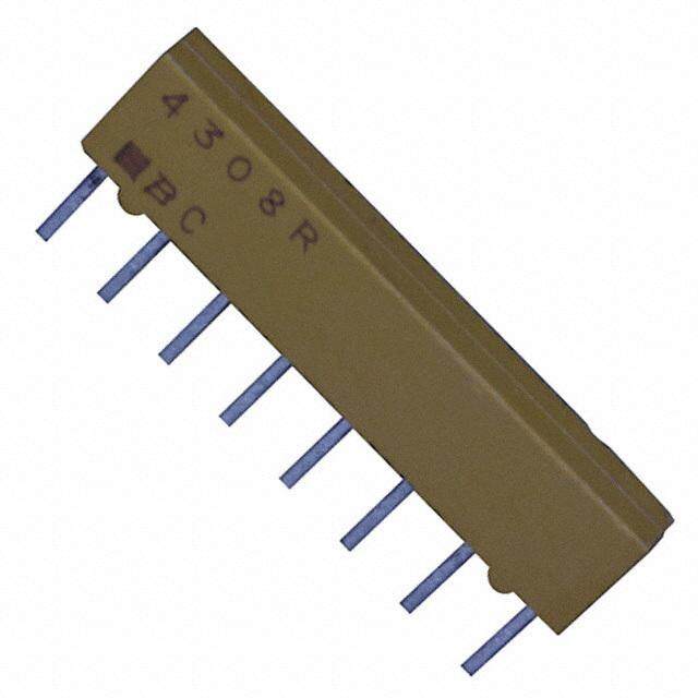
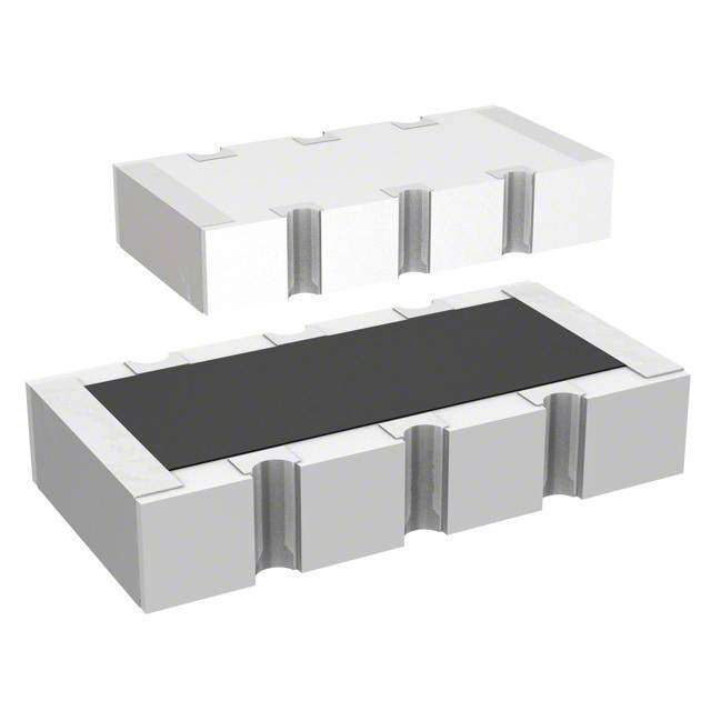
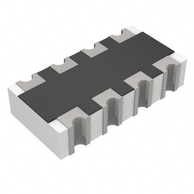
ICGOO电子元器件商城为您提供YC124-JR-0768RL由YAGEO AMERICA CORPORATION设计生产,在icgoo商城现货销售,并且可以通过原厂、代理商等渠道进行代购。 YC124-JR-0768RL价格参考¥0.04-¥0.07。YAGEO AMERICA CORPORATIONYC124-JR-0768RL封装/规格:电阻器网络,阵列, 68 Ohm ±5% 62.5mW Power Per Element 隔离 4 Resistor Network/Array ±200ppm/°C 0804,凸面,长边端子。您可以下载YC124-JR-0768RL参考资料、Datasheet数据手册功能说明书,资料中有YC124-JR-0768RL 详细功能的应用电路图电压和使用方法及教程。
Yageo品牌的YC124-JR-0768RL是一款电阻器网络(阵列电阻),主要应用于需要多个精密电阻集成的电子电路中。该型号常用于消费电子、通信设备、工业控制、汽车电子等领域。其高精度、低温漂和良好的稳定性使其适用于信号处理、电压分压、偏置电路、传感器接口等电路设计。此外,该电阻阵列还适用于自动贴片生产线,适合高密度、高性能要求的电子产品制造。
| 参数 | 数值 |
| 产品目录 | |
| 描述 | RES ARRAY 68 OHM 4 RES 0804 |
| 产品分类 | |
| 品牌 | Yageo |
| 数据手册 | |
| 产品图片 |
|
| 产品型号 | YC124-JR-0768RL |
| rohs | 无铅 / 符合限制有害物质指令(RoHS)规范要求 |
| 产品系列 | YC124 |
| 产品培训模块 | http://www.digikey.cn/PTM/IndividualPTM.page?site=cn&lang=zhs&ptm=4919 |
| 产品目录绘图 |
|
| 产品目录页面 | |
| 供应商器件封装 | 0402 |
| 其它名称 | YC124J-68CT |
| 包装 | 剪切带 (CT) |
| 大小/尺寸 | 0.079" 长 x 0.039" 宽(2.00mm x 1.00mm) |
| 安装类型 | 表面贴装 |
| 容差 | ±5% |
| 封装/外壳 | 0804,凸面,长边端子 |
| 工作温度 | -55°C ~ 155°C |
| 应用 | - |
| 引脚数 | 8 |
| 标准包装 | 1 |
| 每元件功率 | 62.5mW |
| 温度系数 | ±200ppm/°C |
| 电路类型 | 隔离 |
| 电阻(Ω) | 68 |
| 电阻器数 | 4 |
| 高度 | 0.022"(0.55mm) |


- 商务部:美国ITC正式对集成电路等产品启动337调查
- 曝三星4nm工艺存在良率问题 高通将骁龙8 Gen1或转产台积电
- 太阳诱电将投资9.5亿元在常州建新厂生产MLCC 预计2023年完工
- 英特尔发布欧洲新工厂建设计划 深化IDM 2.0 战略
- 台积电先进制程称霸业界 有大客户加持明年业绩稳了
- 达到5530亿美元!SIA预计今年全球半导体销售额将创下新高
- 英特尔拟将自动驾驶子公司Mobileye上市 估值或超500亿美元
- 三星加码芯片和SET,合并消费电子和移动部门,撤换高东真等 CEO
- 三星电子宣布重大人事变动 还合并消费电子和移动部门
- 海关总署:前11个月进口集成电路产品价值2.52万亿元 增长14.8%


PDF Datasheet 数据手册内容提取
120 DATA SHEET ARRAY CHIP RESISTORS YC/TC 5%, 1% sizes YC:102/104/122/124/162/164/248/324/158T/358L/358T TC: 122/124/164 RoHS compliant 7 V. 7 1 0 2 2, 2 t s u g u A – n o ti a c cifi e p s t c u d o r P
Product specification 2 Chip Resistor Surface Mount YC/TC SERIES 102 to 358 12 SCOPE ORDERING INFORM ATIO N - GLOBAL PART NUMBER & 12NC This specificatio n describes Both part numbers ar e iden tified by the series, size, tolerance, packing YC (convex, flat) and TC (concave) type, temperature coefficient, taping reel and resistance value. series chip resi stor arrays with lead- Y YAAGGEEOO BBRRAANNDD oorrddeerriinngg ccooddee free terminations made by thick film process. G LOBAL PART NUMBER (PREFERSRED) YC XXXX X X X X XX XXXX L/T TC (1) (2) (3) (4) (5) (6) (7) (8) APPLICATIONS (1) SIZE Terminal for SDRAM and DDRAM YC:102/104/122/124/162/164/248/324/158T/358L/358T Computer applications: laptop TC: 122/124/164 computer, desktop computer (2) ARRAYS OR NETWORKS Consume electronic equipments: Array YC102/104/122/124/162/164/248/324: - PDAs, PNDs Mobile phone, telecom… Network YC158T/YC358L/YC358T: NA (3) TOLERANCE FEATURES F = ±1% J = ±5% (for Jumper ordering, use code of J) More efficient in pick & place (4) PACKAGING TYPE application R = Paper taping reel K = Embossed plastic tape reel Low assembly costs RoHS compliant (5) TEMPERATURE COEFFICIENT OF RESISTANCE Products with lead free – = Base on spec terminations meet RoHS requirements (6) TAPING REEL Pb-glass contained in electrodes 07 = 7 inch dia. Reel Resistor element and glass are 13 = 13 inch dia. Reel exempted by RoHS (7) RESISTANCE VALUE Reducing environmentally hazardous wastes There are 2~4 digits indicated the resistor value. Letter R/K/M is decimal point. High component and equipment Detailed resistance rules show in table of “Resistance rule of global part number”. reliability (8) DEFAULT CODE Saving of PCB space None forbidden-materials used in Letter L is the system default code for ordering only. (Note) products/production Letter T is the only default code for YC102. Halogen Free Epoxy Resistance rule of global part ORDERING EXAMPLE number The ordering code of a YC122 convex chip resistor array, value 1,000 Ω Resistance code rule Example with ±5% tolerance, supplied in 7-inch tape reel is: YC122-JR-071KL. 0R 0R = Jumper YC158T network, value 100,000Ω with 5% tolerance, supplied in 7-inch 1R = 1 Ω XRXX tape reel is: YC158TJR-07100KL 1R5 = 1.5 Ω (1 to 9.76 Ω) 9R76 = 9.76 Ω XXRX 10R = 10 Ω (10 to 97.6 Ω) 97R6 = 97.6 Ω NOTE 1. All our RSMD products meet RoHS compliant. "LFP" of the internal 2D reel label XXXR 100R = 100 Ω mentions "Lead Free Process" (100 to 976 Ω) 2. On customized label, "LFP" or specific symbol printed and the optional "L" at the end of XKXX 1K = 1,000 Ω GLOBAL PART NUMBER / 12NC can be added (both are on customer request) (1 to 9.76 KΩ) 9K76 = 9760 Ω XM 1M = 1,000,000 Ω (1 MΩ) www.yageo.com Aug. 22, 2017 V.7
Product specification 3 Chip Resistor Surface Mount YC/TC SERIES 102 to 358 12 PP HH YYCCOOMMPP BBRRAANNDD oorrddeerriinngg ccooddeess Both GLOBAL PART NUMBER (preferred) and 12NC (traditional) codes are acceptable to order Phycomp brand produc ts. GLOBAL PART NUMBER (PREFERRED) For detailed information of GLOBAL PART NUMBER and ordering example, please refer to page 2. TC122 series is supplied and ordered by global part number only. 12NC CODE 2350 XXX XXXXX L Last digit of 12NC (1) (2) (3) (4) Resistance decade (3) Last digit TYPE/ START TOL. RESISTANCE PAPER / PE TAPE ON REEL (units) (2) 0.01 to 0.0976 Ω 0 2×0402 IN (1) (%) RANGE 10,000 50,000 0.1 to 0.976 Ω 7 1 to 9.76 Ω 8 ARV321 2350 ±5% 1 to 1 MΩ 013 11xxx 013 12xxx 10 to 97.6 Ω 9 ARV322 2350 ±1% 10 to 1 MΩ 013 2xxxx 013 3xxxx 100 to 976 Ω 1 Jumper 2350 - 0 Ω 013 91001 - 1 to 9.76 KΩ 2 ( 1) The resistors have a 12-digit ordering code starting with 2350. 10 to 97.6 KΩ 3 ( 2) The subsequent 4 or 5 digits indicate the resistor tolerance and 100 to 976 KΩ 4 packaging. 1 to 9.76 MΩ 5 (3) The remaining 4 or 3 digits represent the resistance value with the 10 to 97.6 MΩ 6 last digit indicating the multiplier as shown in the table of “Last digit of 12NC”. Example: 0.02 Ω = 0200 or 200 (4) "L" is optional symbol (Note). 0.3Ω = 3007 or 307 ORDERING EXAMPLE 1Ω = 1008 or 108 The ordering code of a ARV321 resistor, value 1,000Ω with ±5% 33 KΩ = 3303 or 333 tolerance, supplied in tape of 10,000 units per reel is: 235001311102(L) 10 MΩ = 1006 or 106 or YC122-JR-071KL. NOTE 1. All our RSMD products are RoHS compliant. "LFP" of the internal 2D reel label mentions "Lead Free Process" 2. On customized label, "LFP" or specific symbol printed and the optional "L" at the end of GLOBAL PART NUMBER / 12NC can be added (both are on customer request) www.yageo.com Aug. 22, 2017 V.7
Product specification 4 Chip Resistor Surface Mount YC/TC SERIES 102 to 358 12 MARKING YC102 No marking Fig. 1 YC 122 No marking Fig. 2 YC 104 No marking F ig. 3 YC 124 / 1 62 / 164 / 324 0 1-Digit marking F ig. 4 J umper=0Ω 2 E-24 series: 3 digits, 5% First two digits for significant figure and 3rd digit for number of zeros F ig. 4-1 Value=240KΩ YC 248 0 1-Digit marking F ig. 5 Jumper=0Ω E-24 series: 3 digits, 5% 2 First two digits for significant figure and 3rd digit for number of zeros F ig. 5-1 Value=240KΩ YC 158T/ 358L/358T E-24 series: 3 digits 2 First two digits for significant figure and 3rd Fig. 6 Value=24Ω F ig. 6-1 Value=240KΩ digit for number of zeros TC 122 No marking F ig. 7 TC 124 No marking Fig. 8 www.yageo.com Aug. 22, 2017 V.7
Product specification 5 Chip Resistor Surface Mount YC/TC SERIES 102 to 358 12 TC164 0 1-Digit marking Fig. 9 Jumper=0Ω E-24 series: 3 digits, 5% 2 First two digits for significant figure and 3rd digit for number of zeros Fig. 9-1 Value=240KΩ For further marking information, please refer to data sheet “Chip resistors marking”. CO NST RUCTION The resistor is constructed on top OOUUTTLLIINNEESS of a high-grade ceramic body. Internal metal electrodes are added on each end to make the contacts to the thick film resistive element. The composition of the resistive element is a noble metal imbedded into a glass and covered by a second glass to prevent environment influences. The resistor is laser trimmed to the rated resistance value. The resistor Fig. 10 Chip resistor outlines is covered with a protective epoxy coat, finally the two external terminations (matte tin on Ni- barrier) are added as shown in Fig.9. www.yageo.com Aug. 22, 2017 V.7
Product specification 6 Chip Resistor Surface Mount YC/TC SERIES 102 to 358 12 SCHEMATIC Fig. 11 Equivalent circuit diagram Note: 1. YC102/104 is flat type For dimension, please refer to Table 1 Side view for all types YC102_T YC 122/162 YC 104/124/164/324 158/358/248 TC 122 TC 124/164 unit: mm Fig. 12 YC/TC122 series chip resistors dimension Note: (1) YC102/104 is flat type www.yageo.com Aug. 22, 2017 V.7
Product specification 7 Chip Resistor Surface Mount YC/TC SERIES 102 to 358 12 DIMENSIONS Table 1 TYPE H / H1 / HW B P L T W1 W2 YC102 H: 0.25 ± 0.10 0.15 ±0.10 0.55 ±0.10 0.80 ±0.10 0.35 ±0.10 0.15 ±0.10 0.60 ±0.10 YC104 H : 0.20 ± 0.10 0.15 ±0.05 0.40 ±0.10 1.40 ±0.10 0.35 ±0.10 0.15 ±0.10 0.60 ±0.10 YC122 H : 0.21+0.10 / -0.05 0.20 ±0.10 0.67 ±0.05 1.00 ±0.10 0.30 ±0.10 0.25 ±0.10 1.00 ±0.10 H : 0.35 ±0.10 W YC124 H: 0.45 ± 0.05 0.20 ±0.15 0.50 ±0.05 2.00 ±0.10 0.45 ±0.10 0.30 ±0.15 1.00 ±0.10 H: 0.30 ± 0.05 1 YC162 H : 0.30 ±0.10 0.30 ±0.10 0.80 ±0.05 1.60 ±0.10 0.40 ±0.10 0.30 ±0.10 1.60 ±0.10 H : 0.65 ±0.15 W H : 0.65 ±0.05 YC164 0.30 ±0.15 0.80 ±0.05 3.20 ±0.15 0.60 ±0.10 0.30 ±0.15 1.60 ±0.15 H: 0.50 ±0.15 1 H : 0.45 ±0.05 YC248 0.30 ±0.15 0.50 ±0.05 4.00 ±0.20 0.45 ±0.10 0.40 ±0.15 1.60 ±0.15 H: 0.30 ±0.05 1 H : 1.10 ±0.15 YC324 0.50 ±0.20 1.27 ±0.05 5.08 ±0.20 0.60 ±0.10 0.50 ±0.15 3.20 ±0.20 H: 0.90 ±0.15 1 TC122 H : 0.30 ±0.05 0.25 ±0.15 0.50 ±0.05 1.00 ±0.10 0.30 ±0.10 0.25 ±0.15 1.00 ±0.10 TC124 H : 0.30 ±0.10 0.20 ±0.10 0.50 ±0.05 2.00 ±0.10 0.40 ±0.10 0.25 ±0.10 1.00 ±0.10 TC164 H : 0.50 ±0.15 0.30 ±0.15 0.80 ±0.05 3.20 ±0.15 0.60 ±0.10 0.30 ±0.15 1.60 ±0.15 YC158T H : 0.45±0.05 0.30 ±0.15 0.64 ±0.05 3.20 ±0.20 0.60 ±0.10 0.35 ±0.15 1.60 ±0.15 H: 0.32± 0.05 1 YC358L H : 1.10±0.15 0.50 ±0.15 1.27 ±0.05 6.40 ±0.20 0.60 ±0.10 0.50 ±0.15 3.20 ±0.20 YC358T H: 0.90±0.15 1 www.yageo.com Aug. 22, 2017 V.7
Product specification 8 Chip Resistor Surface Mount YC/TC SERIES 102 to 358 12 ELECTRICAL CHARACTERISTICS Table 2 POWER Jumper criteria TYPE OPERATING MWV RCOV DWV RESISTANCE RANGE & T. C. R. P70 TEMP. RANGE TOLERANCE (unit: A) E24 ±5% 10Ω ≤ R ≤ 1MΩ YC102 1/32W -55°C to +125°C 15V 30V 30V E24/E96 ±1% 10Ω ≤ R ≤ 1MΩ Rated current 0.5 Max. current 1.0 Jumper < 0.05Ω ±200 ppm/°C E24 ±5% 10Ω ≤ R ≤ 1MΩ YC104 1/32W -55°C to +125°C 12.5V 25V 25V E24/E96 ±1% 10Ω ≤ R ≤ 1MΩ Rated current 0.5 Max. current 1.0 Jumper < 0.05Ω E24 ±5% 1Ω ≤ R ≤ 1MΩ YC122 1/16W -55°C to +155°C 50V 100V 100V E24/E96 ±1% 1Ω ≤ R ≤ 1MΩ Rated current 0.5 Max. current 1.0 Jumper < 0.05Ω 1Ω ≤ R ≤ 10Ω E24 ±5% 1Ω ≤ R ≤ 1MΩ YC124 1/16W -55°C to +155°C 25V 50V 100V E24/E96 ±1% 1Ω ≤ R ≤ 1MΩ ±250 ppm/°C Rated current 1.0 10Ω ≤ R ≤ 1MΩ Max. current 2.0 Jumper < 0.05Ω ±200 ppm/°C E24 ±5% 1Ω ≤ R ≤ 1MΩ YC162 1/16W -55°C to +155°C 50V 100V 100V E/24/E96 ±1% 1Ω ≤ R ≤ 1MΩ Rated current 1.0 Max. current 2.0 Jumper < 0.05Ω E24 ±5% 1Ω ≤ R ≤ 1MΩ YC164 1/16W -55°C to +155°C 50V 100V 100V E24/E96 ±1% 1Ω ≤ R ≤ 1MΩ Rated current 1.0 Max. current 2.0 Jumper < 0.05Ω E24 ±5% 10Ω ≤ R ≤ 1MΩ YC248 1/16W -55°C to +155°C 50V 100V 100V E24/E96 ±1% 10Ω ≤ R ≤ 1MΩ Rated current 2.0 Max. current 10.0 Jumper < 0.05Ω YC324 1/8W -55°C to +155°C 200V 500V 500V E24 ±5% 10Ω ≤ R ≤ 1MΩ --- --- E24/E96 ±1% 10Ω ≤ R ≤ 1MΩ E24 ±5% 10Ω ≤ R ≤ 1MΩ TC122 1/16W -55°C to +125°C 50V 100V 100V E24/E96 ±1% 10Ω ≤ R ≤ 1MΩ Rated current 1.0 Max. current 1.5 Jumper < 0.05Ω ±200 ppm/°C E24 ±5% 10Ω ≤ R ≤ 1MΩ TC124 1/16W -55°C to +125°C 50V 100V 100V E24/E96 ±1% 10Ω ≤ R ≤ 1MΩ Rated current 1.0 Max. current 1.5 Jumper < 0.05Ω E24 ±5% 10Ω ≤ R ≤ 1MΩ TC164 1/16W -55°C to +155°C 50V 100V 100V E24/E96 ±1% 10Ω ≤ R ≤ 1MΩ Rated current 1.0 Max. current 2.0 Jumper < 0.05Ω YC158T 1/16W -55°C to +155°C 25V 50V 50V E24 ±5% 10Ω ≤ R ≤ --- --- 100KΩ YC358L 10Ω ≤ R ≤ 1/16W -55°C to +155°C 50V 100V 100V E24 ±5% --- --- YC358T 330KΩ FOOTPRINT AND SOLDERING PROFILES For recommended footprint and soldering profiles, please refer to data sheet “Chip resistors mounting”. PACKING STYLE AND PACKAGING QUANTITY Table 3 Packing style and packaging quantity PAC KING STYLE PACKING STYLE YC102/ YC/TC YC/TC YC162 YC/TC YC248 YC324 YC158T YC358L 104 122 124 164 YC358T Paper taping reel ( R ) 7" (178mm) 10,000 10,000 10,000 5,000 5,000 5,000 --- 5,000 --- 13" (254mm) 50,000 50,000 40,000 --- 20,000 --- --- 20,000 --- Embossed taping reel ( K) 7" (178mm) --- --- --- --- --- 4,000 4,000 --- 4,000 NOTE 1. For tape and reel specification/dimensions, please refer to data sheet “Chip resistors packing”. www.yageo.com Aug. 22, 2017 V.7
Product specification 9 Chip Resistor Surface Mount YC/TC SERIES 102 to 358 12 FUNCTIONAL DESCRIPTION OOPPEERRAATTIINNGG TTEEMMPPEERRAATTUURREE RRAANNGGEE YC102/104/122/162, TC122/124 Range: -55℃ to +125℃ (Fig.13) YC124/164/24 8/324/158T/358L/358T, TC164 Range: -55℃ to +155℃(Fig.14) PPOOWWEERR RRAATTIINNGG Each type rated power at 70℃ YC102/104 = 1/32 W YC122/124/162/164/248/158T/358L/358T = 1/16 W YC324 = 1/8 W TC122/124/164 = 1/16 W Fig. 13 Maximum dissipation (P) in percentage of rated power as a function of the operating ambient temperature (T ) amb RATED VOLTAGE The DC or AC (rms) continuous working voltage corresponding to the rated power is determined by the following formula: V= (PxR) or max. working voltage whichever is less Where V=Continuous rated DC or AC (rms) working voltage (V) P=Rated power (W) R=Resistance value (Ω) Fig. 14 Maximum dissipation (P) in percentage of rated power as a function of the operating ambient temperature (T ) amb www.yageo.com Aug. 22, 2017 V.7
Product specification 10 Chip Resistor Surface Mount YC/TC SERIES 102 to 358 12 TESTS AND REQUIREMENTS Table 4 Test condition, procedure and requirements TEST TEST METHOD PROCEDURE REQUIREMENTS Life/ MIL-STD-202G-method 108A 1,000 hours at 70±5 °C applied RCWV ±(2%+0.05 Ω) Operational Life / IEC 60115-1 4.25.1 1.5 hours on, 0.5 hour off, still air required <100 mΩ for Jumper Endurance JIS C 5202-7.10 High Temperature MIL-STD-202G-method 108A 1,000 hours at maximum operating ±(1%+0.05 Ω) Exposure/ IEC 60115-1 4.25.3 temperature depending on specification, <50 mΩ for Jumper Endurance at unpowered JIS C 5202-7.11 Upper Category No direct impingement of forced air to the Temperature parts Tolerances: 125±3 °C Moisture MIL-STD-202G-method 106F Each temperature / humidity cycle is defined at ±(2%+0.05 Ω) Resistance IEC 60115-1 4.24.2 8 hours (method 106F), 3 cycles / 24 hours for <100 mΩ for Jumper 10d with 25 °C / 65 °C 95% R.H, without steps 7a & 7b, unpowered Parts mounted on test-boards, without condensation on parts Measurement at 24±2 hours after test conclusion Thermal Shock MIL-STD-202G-method 107G -55/+125 °C ±(1%+0.05 Ω) Note: Number of cycles required is 300. <50 mΩ for Jumper Devices mounted Maximum transfer time is 20 seconds. Dwell time is 15 minutes. Air – Air Short Time MIL-R-55342D-para 4.7.5 2.5 times RCWV or maximum overload ±(2%+0.05 Ω) Overload IEC60115-1 4.13 voltage whichever is less for 5 sec at room <50 mΩ for Jumper temperature No visible damage Board Flex/ IEC60115-1 4.33 Device mounted on PCB test board as ±(1%+0.05 Ω) Bending described, only 1 board bending required <50 mΩ for Jumper 3 mm bending No visible damage Bending time: 60±5 seconds Ohmic value checked during bending www.yageo.com Aug. 22, 2017 V.7
Product specification 11 Chip Resistor Surface Mount YC/TC SERIES 102 to 358 12 TEST TEST METHOD PROCEDUR E REQUIREMENTS Solderability - Wetting IPC/JEDECJ-STD-002B test B Electrical Test not required Well tinned (≥95% covered) No visible damage IEC 60068-2-58 Magnification 50X SMD conditions: 1st step: method B, aging 4 hours at 155 °C dry heat 2nd step: leadfree solder bath at 245±3 °C Dipping time: 3±0.5 seconds - Leaching IPC/JEDECJ-STD-002B test D Leadfree solder, 260 °C, 30 seconds No visible damage IEC 60068-2-58 immersion time - Resistance to MIL-STD-202G-method 210F Condition B, no pre-heat of samples ±(1%+0.05 Ω) Soldering Heat IEC 60068-2-58 Leadfree solder, 260 °C, 10 seconds <50 mΩ for Jumper immersion time No visible damage Procedure 2 for SMD: devices fluxed and cleaned with isopropanol www.yageo.com Aug. 22, 2017 V.7
Product specification 12 Chip Resistor Surface Mount YC/TC SERIES 102 to 358 12 REVISION HISTORY REVISION DATE CHANGE DESCRIPTION NOTIFICATION Version 7 Aug. 22, 2017 - - Correct the typo for YC158T/358L/358T, Marking, "240" is 24ohm Version 6 Ju n. 1, 2017 - - Update ordering information for networks YC158T/YC358L/YC358T Version 5 Feb. 14, 2017 - - Update YC158 and 358 part number to YC158T , YC358L and YC358T Version 4 Dec. 22, 2016 - - Delete YC102 default code L type Version 3 Apr. 29, 2016 - - Update YC series and TC164 dimension Version 2 Dec. 11, 2015 - - Update Operating Temperature Version 1 Feb. 04, 2015 - - Update YC102 to flat type Version 0 Nov. 14, 2014 - - First issue of this specification “ Yageo reserves all the rights for revising the content of this datasheet without further notification, as long as the products itself are unchanged. Any product change will be announced by PCN.” www.yageo.com Aug. 22, 2017 V.7
Mouser Electronics Authorized Distributor Click to View Pricing, Inventory, Delivery & Lifecycle Information: Y ageo: TC164-FR-0733R2L TC164-FR-0724RL TC164-FR-0727RL TC164-FR-0751RL TC164-FR-072K21L TC164-FR- 078K25L TC164-FR-0715KL TC164-FR-071ML TC164-FR-0724R9L TC164-FR-07499RL TC164-FR-072K7L TC164-FR-072KL TC164-FR-077K5L TC124-JR-077R5L TC124-JR-073RL TC164-FR-0756RL TC164-FR-0751R1L TC164-FR-072K4L TC164-FR-07330KL TC164-FR-07402RL TC124-FR-074K7L TC124-FR-0739RL TC164-FR- 0718RL TC164-FR-0713KL TC164-FR-077K68L TC124-FR-0747RL TC164-FR-073K32L TC164-FR-071K82L TC164-FR-071K3L TC164-FR-0746R4L TC164-FR-0762KL TC164-FR-0711KL TC164-FR-07560KL TC124-JR- 075R1L TC164-FR-07430KL TC124-FR-07100KL TC164-FR-07200KL TC164-FR-07510RL TC124-FR-0722RL TC124-FR-0733RL TC164-JR-075R1L TC164-FR-0727R4L TC164-FR-07680KL TC124-FR-07330RL TC124-FR- 075K1L TC164-JR-073RL TC164-FR-0736KL TC124-FR-071KL TC124-FR-0756RL TC124-FR-072K4L TC164-FR- 078K2L TC164-FR-0782KL TC164-FR-071K62L TC124-FR-0760R4L TC124-FR-0724R9L TC164-FR-0724KL TC164-FR-0756KL TC122-JR-073RL TC164-FR-07110RL TC164-FR-0718KL TC164-FR-0775RL TC164-FR- 07390KL TC164-FR-0756R2L TC164-FR-0730R1L TC164-FR-076K8L TC164-FR-07332RL TC164-FR-076K2L TC164-FR-073KL TC164-FR-0775KL TC164-FR-07120KL TC164-FR-0751K1L TC164-FR-079K1L TC164-FR- 075K1L TC164-FR-07180RL TC164-FR-0739KL TC164-FR-0791KL TC164-FR-071K2L TC164-FR-07750RL TC164-FR-07150KL TC164-FR-0751KL TC164-FR-0784R5L TC164-FR-07200RL TC124-FR-0762RL TC164-FR- 073K6L TC124-FR-0727R4L TC164-FR-0739RL TC124-FR-0751RL TC124-FR-0733KL TC124-FR-0710KL TC124- FR-0749R9L TC164-FR-07160KL TC124-FR-07619RL TC164-FR-1320KL TC164-JR-1322KL TC164-JR-1327KL TC164-FR-1347KL TC164-JR-10100KL TC124-JR-0782RL TC164-FR-1368KL TC164-JR-132K2L