首页 > Y14880R00100D9R > 详情
 Datasheet下载
- 型号: Y14880R00100D9R
- 制造商: Vishay Precision Group
- 库位|库存: xxxx|xxxx
- 要求:
| 数量阶梯 | 香港交货 | 国内含税 |
| +xxxx | $xxxx | ¥xxxx |
查看当月历史价格
查看今年历史价格
产品参数
| 参数 | 数值 |
| 产品目录 | 电阻器无源元件 |
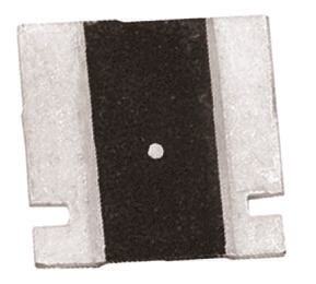
| 描述 | RES 0.001 OHM 3W .5% 3637电流传感电阻器 - SMD 0.001ohms 0.5% 3w |
| 产品分类 | 芯片电阻 - 表面安装电阻器 |
| 品牌 | Vishay Precision Group Foil Resistors |
| 产品手册 | http://www.vishaypg.com/doc?63089 |
| 产品图片 |   |
| rohs | 符合RoHS无铅 / 符合限制有害物质指令(RoHS)规范要求 |
| 产品系列 | 电流传感电阻器,电流传感电阻器 - SMD,Vishay Precision Group Foil Resistors Y14880R00100D9RCSM |
| 数据手册 | 点击此处下载产品Datasheet |
| 产品型号 | Y14880R00100D9R |
| 产品 | Metal Element Current Sensing Resistors |
| 产品种类 | 电流传感电阻器 - SMD |
| 供应商器件封装 | - |
| 其它名称 | Y1488-.001ADKR |
| 其它有关文件 | 点击此处下载产品Datasheet |
| 功率(W) | 3W |
| 功率额定值 | 3 W |
| 包装 | Digi-Reel® |
| 单位重量 | 290 mg |
| 商标 | Vishay Precision Group Foil Resistors |
| 外壳代码-in | 3637 (Reversed) |
| 外壳代码-mm | 9194 (Reversed) |
| 外壳宽度 | 9.398 mm |
| 外壳长度 | 9.144 mm |
| 外壳高度 | 0.635 mm |
| 大小/尺寸 | 0.360" 长 x 0.370" 宽(9.14mm x 9.40mm) |
| 容差 | 0.5 % |
| 封装 | Reel |
| 封装/外壳 | 3637 |
| 封装/箱体 | 3637 (9194 metric) Reversed |
| 工作温度范围 | - 55 C to + 125 C |
| 成分 | 金属箔 |
| 标准包装 | 1 |
| 温度系数 | 15 PPM / C |
| 特性 | 电流感应, 防潮 |
| 电阻 | 0.001 Ohms |
| 电阻(Ω) | 0.001 |
| 端子数 | 4 |
| 端接类型 | SMD/SMT |
| 系列 | CSM |
| 高度 | 0.035"(0.89mm) |
Datasheet
PDF Datasheet 数据手册内容提取
CSM Series Bulk Metal® Technology High Precision, Current Sensing, Power Surface Mount, Metal Strip Resistor with Resistance Value from 1 m, Rated Power up to 3 W and TCR to 0 ± 15 ppm/°C Maximum FEATURES Temperature coefficient of resistance: ± 15 ppm/°C max. (- 55 °C to + 125 °C, + 25 °C ref.); ± 10 ppm/°C max. (- 55 °C to + 125 °C, + 25 °C ref.) is available on request (see table 1) Power rating: 1 W to 3 W Resistance tolerance: ± 0.1 % No minimum order quantity and any value at any Resistance range: 1 m to 200 m tolerance available within resistance range. Bulk Metal® Foil resistors are not restricted to standard The Vishay Foil Resistors (VFR) application engineering department is available to advise and make values, specific “as required” values can be supplied at no recommendations. extra cost or delivery (e.g. 2.3456 m vs. 2 m) For non-standard technical requirements and special Load life stability to ± 0.2 % (70 °C, 2000 h at rated power) applications, please contact foil@vpgsensors.com. Short time overload: ± 0.1 % typical B C Thermal EMF: 3 µV/°C (DC offset error, significant for low values) R I I Maximum current: up to 54 A A D Proprietary processing techniques produce low TCR, tight tolerance and improve stability V Zin =~∞ Low inductance < 5 nH Solderable terminations Four terminal (Kelvin) design: allows for precise and accurate measurements. Excellent frequency response to 50 MHz Matched sets are available on request FIGURE 1 - POWER DERATING CURVE Screening in accordance with EEE-INST002 available + 70 °C (per MIL-PRF-55342 and MIL-PRF-49465; see 303144 100 %) and 303145 datasheets) 80 r ( Terminal finishes available: lead (Pb)-free, tin/lead alloy e w 60 Quick prototype quantities available, please contact o d P 40 foil@vpgsensors.com ate 20 For better performance please contact Application R Engineering 0 - 65- 50 - 25 0 25 50 75 100 125 150 170 Compliant to RoHS directive 2002/95/EC Ambient Temperature (°C) TABLE 1 - SPECIFICATIONS PARAMETER CSM2512 CSM3637 Resistance Range 1 m to 200 m Power Rating at 70 °C 1 W (1) 3 W ( 1 m to 10 m) 2 W (> 10 m to 200 m) Maximum Current (2) 31 A 54 A ± 0.5 % (1 m to < 3 m) ± 0.5 % (1 m to < 2 m) Tolerance ± 0.1 % (3 m to 200 m) ± 0.1 % (2 m to 200 m) Temperature Coefficient ± 50 ppm/°C (1 m to < 3 m) ± 25 ppm/°C (1 m to < 3 m) Max. (- 55 °C to + 125 °C, ± 15 ppm/°C (3 m to 200 m) ± 15 ppm/°C (3 m to 200 m) + 25 °C Ref.) ± 10 ppm/°C (3 m to 10 m) is available on request (3) ± 10 ppm/°C (1 m to 10 m) is available on request (3) Operating Temperature - 65 °C to + 170 °C Range Maximum Working Voltage (P x R)1/2 Weight (Maximum) 0.09 g 0.29 g Notes (1) For values above 0.1 derate linearly to 80 % rated power at 0.5 (2) Maximum current for a given resistance value is calculated using I = PR (3) Please contact application engineering: foil@vpgsensors.com * This datasheet provides information about parts that are RoHS-compliant and/or parts that are non-RoHS-compliant. For example, parts with lead (Pb) terminations are not RoHS compliant. Please see the information/tables in this datasheet for details. Document Number: 63089 For any questions, contact www.vishayfoilresistors.com Revision: 17-Aug-15 foil@vpgsensors.com 1
CSM Series ABOUT CSM (Low Ohm Value 1 m to 200 m) New high-precision Bulk Metal® surface-mount Power Metal in critical locations can greatly improve circuit performance, Strip® resistor of 1 m to 200 m that features an improved long-term application-related performance, as well as the load-life stability of ± 0.2 % at + 70 °C for 2000 h at rated designer’s peace-of-mind. power, an absolute TCR of ± 15 ppm/°C maximum from Additionally, the overall system cost is often reduced when a - 55 °C to + 125 °C, + 25 °C ref., and a tolerance of ± 0.1 %. knowledgeable designer concentrates costs in a few Typical current sensing resistors offer a load-life stability of exceptionally stable components whose proven minimal- 1 % through a 2000 h workload. The improved resistance deviation load and environmental stability can often eliminate stability of the CSM Series makes it ideal for the necessity of additional compensating circuitry or tightened-stability voltage division and precision current temperature-controlling systems. The higher reliability and sensing applications in switching linear power supplies, better overall system performances also achieve excellent power amplifiers, measurement instrumentation, bridge product results in the field, enhancing market acceptance networks, and medical and test equipment. In addition, the and product reputation. CSM Series complies with EEE-INST-002 (MIL-PRF 55342 Designers often unnecessarily pay for tighter tolerances than and MIL-PRF 49465) for military and space applications. required simply to accommodate the resistance stability Traditional Passive current sensors and shunts generate shifts they know to be imminent in an application due to the heat under power, which changes their resistance, and thus large application-related changes in the components they their voltage output. The CSM’s low absolute TCR reduces selected. Selection of a high-stability component like the errors due to temperature gradients, thus reducing a major CSM in these applications eliminates the need for shift source of uncertainty in current measurement. The CSM allowance due to “planned instability” and allows the use of can withstand unconventional environmental conditions, looser initial tolerances than would be necessary with including the extremely high temperatures and radiation-rich current-sensing resistors based on other technologies. environments of down-hole oil exploration and well logging, The Key Applications or the deep-sea underwater repeaters in cross-ocean communications. Applications requiring accuracy and repeatability under stress conditions such as the following: The stability of the CSM can be further enhanced by post-manufacturing operations (PMO), such as temperature Switching and linear power supplies cycling, short-time overload, and accelerated load life which Precision current-sensing are uniquely applicable to Bulk Metal® Foil resistors. Power management systems The device features a low thermal electromotive force (EMF) Feedback circuits that is critical in many precision applications. The CSM’s Power amplifiers all-welded construction is composed of a Bulk Metal® resistive element with welded copper terminations, plated for Measurement instrumentation soldering. The terminations make true ohmic contact with the Precision instrumentation amplifiers resistive layer along the entire side of the resistive element, Medical and automatic test equipment thereby minimizing temperature variations. Also, the resistor Satellites and aerospace systems element is designed to uniformly dissipate power without creating hot spots, and the welded terminations material is Commercial and Military avionics compatible with the element material. Test and measurement equipment These design factors result in a very low thermal-EMF Electronic scales (3 µV/°C) resistor, because in addition to the low thermal EMF compatibility of the metals, the uniformity and thermal efficiency of the design minimizes the temperature differential across the resistor, thereby assuring low thermal EMF generation at the leads. This further reduces the “battery effect” exhibited by most current-sensing or voltage-reference resistors. Thus, the parasitic voltage generated at the junction of two dissimilar metals, which is especially important in low-value current-sensing resistors, is minimized, while the pure current-to-voltage conversion is protected from such interference in DC applications. The stability problems associated with analog circuits are very pervasive, but knowledgeable selection of a few high-quality resistors, networks, or trimming potentiometers www.vishayfoilresistors.com For any questions, contact Document Number: 63089 2 foil@vpgsensors.com Revision: 17-Aug-15
CSM Series FIGURE 2 - DIMENSIONS AND IMPRINTING in inches (millimeters) CSM2512 DIMENSIONS CSM3637 DIMENSIONS (1) (1) H H A B B A L T L W W T CSM2512 LAND PATTERN CSM3637 LAND PATTERN E I 1 1 e E1 I1 E2 E2 I d c 2 c I I 2 d Kelvin Connection a b I b I, I - Current E1, 2E - Sense a 1 2 DIMENSIONS - TOLERANCES ± 0.010 (± 0.254), * ± 0.015 (± 0.381) MODEL RESISTANCE RANGE (m) L W H T A B 1 to < 5 0.087 (2.210) CSM2512 5 to < 7 0.250 (6.350) 0.125 (3.175) 0.025 (0.635) 0.047 (1.194) 0.030 (0.762)* 0.032 (0.813)* 7 to 200 0.030 (0.762) 1 to < 2 0.360 (9.144) 0.370 (9.398) 0.025 (0.635) 0.138 (3.505) 0.061 (1.55) 0.032 (0.813) CSM3637 2 to 200 0.360 (9.144) 0.370 (9.398) 0.025 (0.635) 0.086 (2.184) 0.061 (1.549) 0.032 (0.813) LAND PATTERN DIMENSIONS - TOLERANCES ± 0.003 (± 0.076) MODEL RANGE a b c d e I 0R001 to 0R0049 0.120 (3.05) 0.145 (3.68) 0.045 (1.14) 0.021 (0.53) 0.055 (1.39) 0.050 (1.27) CSM2512 0R005 to 0R0069 0.083 (2.10) 0.145 (3.68) 0.045 (1.14) 0.021 (0.53) 0.055 (1.39) 0.125 (3.17) 0R007 to 0R2 0.065 (1.65) 0.145 (3.68) 0.045 (1.14) 0.021 (0.53) 0.055 (1.39) 0.160 (4.06) 0R001 to 0R0019 0.168 (4.27) 0.390 (9.91) 0.066 (1.68) 0.024 (0.610) - 0.074 (1.88) CSM3637 0R002 to 0R2 0.116 (2.95) 0.390 (9.91) 0.066 (1.68) 0.024 (0.610) - 0.178 (4.52) Note (1) White dot indicates top side of part for mounting purposes Document Number: 63089 For any questions, contact www.vishayfoilresistors.com Revision: 17-Aug-15 foil@vpgsensors.com 3
CSM Series TABLE 2 - CSM SERIES PERFORMANCE SPECIFICATIONS MIL-PRF-49465B CSM2512/CSM3637 TEST CONDITIONS R LIMITS TYPICAL R LIMITS MAXIMUM R LIMITS - 55 °C to + 150 °C, 1000 cycles, Thermal Shock ± (0.5 % + 0.0005R) 0.1 % 0.3 % 15 min at each extreme Load Life Stability 2000 h, 70 °C at rated power ± (1.0 % + 0.0005R) 0.2 % 1.0 % + 85 °C, 85 % humidity Bias Humidity ± (0.5 % + 0.0005R) 0.05 % 0.2 % 10 % bias, 1000 h 5 x rated power for 5 s Short Time Overload ± (0.5 % + 0.0005R) 0.1 % 0.3 % (See note (3) from table 1) High Temperature Exposure 1000 h, 170 °C ± (1.0 % + 0.0005R) 0.2 % 0.3 % Low Temperature Storage - 65 °C for 24 h ± (0.5 % + 0.0005R) 0.05 % 0.1 % MIL-STD-202, method 106, Moisture Resistance ± (0.5 % + 0.0005R) 0.02 % 0.05 % 0 power, 7a and 7b not required Shock 100 g, 6 ms, 5 pulses ± (0.1 % + 0.0005R) 0.02 % 0.05 % Vibration (10 Hz to 2000 Hz) 20 g ± (0.1 % + 0.0005R) 0.02 % 0.05 % Resistance to Soldering Heat 10 s to 12 s at + 260 °C ± (0.25 % + 0.0005R) 0.05 % 0.1 % Solderability MIL-STD-202 95 % coverage - - FIGURE 3 - LOAD LIFE RESULTS OF CSM2512 CSM2512 0R05 Load Life 2000HRS @ 1W @ +70C (15 units) 3000 2500 2000 1500 1000 m) 500 p p 0 R ( R/ -500 0 500 1000 1500 2000 2500 (cid:3) -1000 -1500 -2000 -2500 -3000 Time (Hours) www.vishayfoilresistors.com For any questions, contact Document Number: 63089 4 foil@vpgsensors.com Revision: 17-Aug-15
CSM Series FIGURE 4 - THERMAL SHOCK RESULTS OF CSM3637 AND CSM2512 Thermal Shock (-55°C to +150°C) x 1000 Cycles 20 Units Each Type and Value 2000 1500 1000 m) 500 p p 0 R ( R/ -500 ∆ -1000 -1500 -2000 CSM3637 0R1 CSM3637 0R2 CSM2512 0R1 CSM2512 0R2 Type and Value FIGURE 5 - BIAS HUMIDITY RESULTS OF CSM3637 AND CSM2512 Bias Humidity 1000 Hrs @ +85°C @ 85% RH 10 Units Each Type and Value 1000 800 600 400 m) 200 p p R ( 0 R/ ∆ -200 -400 -600 -800 -1000 CSM3637 0R2 CSM3637 0R1 CSM2512 0R1 CSM2512 0R2 Type and Value Document Number: 63089 For any questions, contact www.vishayfoilresistors.com Revision: 17-Aug-15 foil@vpgsensors.com 5
CSM Series FIGURE 6 - PULSE TEST I CSM3637 0R005 Test - 10 units (5 Pulses of 5 sec @ 30 A, 10 sec @ 0 A) Average Resistance Deviation: 696 ppm STD = 305 ppm, Measurement Error = 0.0005R 35 30 A) 25 nt ( 20 re 15 r u C 10 5 0 5 sec 10 sec Time (sec) FIGURE 7 - PULSE TEST II CSM3637 0R005 Pulse Test - 10 units (35 Pulses of 0.2 msec @ 20 A, 0.5 msec @ 3 A) Average Resistance Deviation: 13.3 ppm STD = 27.3 ppm, Measurement Error = 0.0005R 25 A) 20 nt ( 15 re 10 r u C 5 0 0.2 0 .5 msec msec Time (msec) www.vishayfoilresistors.com For any questions, contact Document Number: 63089 6 foil@vpgsensors.com Revision: 17-Aug-15
CSM Series TABLE 3 - GLOBAL PART NUMBER INFORMATION (1) NEW GLOBAL PART NUMBER: Y14870R12400B0R (preferred part number format) DENOTES PRECISION VALUE CHARACTERISTICS Y R = 0 = standard 9 = lead (Pb)-free 1 to 999 = custom Y 1 4 8 7 0 R 1 2 4 0 0 B 0 R PRODUCT CODE RESISTANCE TOLERANCE PACKAGING 1487 = CSM2512 B = ± 0.1 % W = waffle 1488 = CSM3637 C = ± 0.25 % R = tape and reel D = ± 0.5 % F = ± 1.0 % FOR EXAMPLE: ABOVE GLOBAL ORDER Y1487 0R12400 B 0 R: TYPE: CSM2512 VALUE: 124.0 m ABSOLUTE TOLERANCE: ± 0.1 % TERMINATION: standard tin/lead PACKAGING: tape and reel HISTORICAL PART NUMBER: CSM2512 0R1240 B B T (will continue to be used) CSM2512 0R1240 B B T MODEL OHMIC VALUE ABS. TOLERANCE TERMINATION PACKAGING 0.124 B = ± 0.1 % S = lead (Pb)-free T = tape and reel C = ± 0.25 % B = tin/lead W = waffle pack D = ± 0.5 % F = ± 1.0 % Note (1) For non-standard requests, please contact application engineering Document Number: 63089 For any questions, contact www.vishayfoilresistors.com Revision: 17-Aug-15 foil@vpgsensors.com 7
LLeeggaall DDiissccllaaiimmeerr NNoottiiccee Vishay Precision Group, Inc. DDiissccllaaiimmeerr ALL PRODUCTS, PRODUCT SPECIFICATIONS AND DATA ARE SUBJECT TO CHANGE WITHOUT NOTICE. Vishay Precision Group, Inc., its affiliates, agents, and employees, and all persons acting on its or their behalf (collectively, “VPG”), disclaim any and all liability for any errors, inaccuracies or incompleteness contained herein or in any other disclosure relating to any product. The product specifications do not expand or otherwise modify VPG’s terms and conditions of purchase, including but not limited to, the warranty expressed therein. VPG makes no warranty, representation or guarantee other than as set forth in the terms and conditions of purchase. To the maximum extent permitted by applicable law, VPG disclaims (i) any and all liability arising out of the application or use of any product, (ii) any and all liability, including without limitation special, consequential or incidental damages, and (iii) any and all implied warranties, including warranties of fitness for particular purpose, non-infringement and merchantability. Information provided in datasheets and/or specifications may vary from actual results in different applications and performance may vary over time. Statements regarding the suitability of products for certain types of applications are based on VPG’s knowledge of typical requirements that are often placed on VPG products. It is the customer’s responsibility to validate that a particular product with the properties described in the product specification is suitable for use in a particular application. You should ensure you have the current version of the relevant information by contacting VPG prior to performing installation or use of the product, such as on our website at vpgsensors.com. No license, express, implied, or otherwise, to any intellectual property rights is granted by this document, or by any conduct of VPG. The products shown herein are not designed for use in life-saving or life-sustaining applications unless otherwise expressly indicated. Customers using or selling VPG products not expressly indicated for use in such applications do so entirely at their own risk and agree to fully indemnify VPG for any damages arising or resulting from such use or sale. Please contact authorized VPG personnel to obtain written terms and conditions regarding products designed for such applications. Product names and markings noted herein may be trademarks of their respective owners. Copyright Vishay Precision Group, Inc., 2014. All rights reserved. Document No.: 63999 www.vpgsensors.com Revision: 15-Jul-2014 1
Mouser Electronics Authorized Distributor Click to View Pricing, Inventory, Delivery & Lifecycle Information: V ishay Precision Group: Y14870R00500B9R Y14880R00500B9R Y14870R01000B9R Y14870R05000B9R Y14880R00500F9R Y14870R02000F0W Y14870R05000F9W Y14870R02500F0R Y14880R00200B9R Y14880R20000B0R Y14870R10000B9R Y14880R00100D9R Y14880R00300B0R Y14880R00150D0W Y14880R00500D0R Y14880R00300D0R Y14880R00400D0R Y14880R02000D0R Y14880R00200D0R Y14870R01000B0R Y14870R00500B0R Y14870R20000B9W Y14880R07500F9R Y14880R02000B9R Y14880R01000D9R