ICGOO在线商城 > 电阻器 > 芯片电阻 - 表面安装 > Y14730R02000B9R
/Y14730R02000B9R.jpg)
 Datasheet下载
- 型号: Y14730R02000B9R
- 制造商: Vishay Precision Group
- 库位|库存: xxxx|xxxx
- 要求:
| 数量阶梯 | 香港交货 | 国内含税 |
| +xxxx | $xxxx | ¥xxxx |
查看当月历史价格
查看今年历史价格
Y14730R02000B9R产品简介:
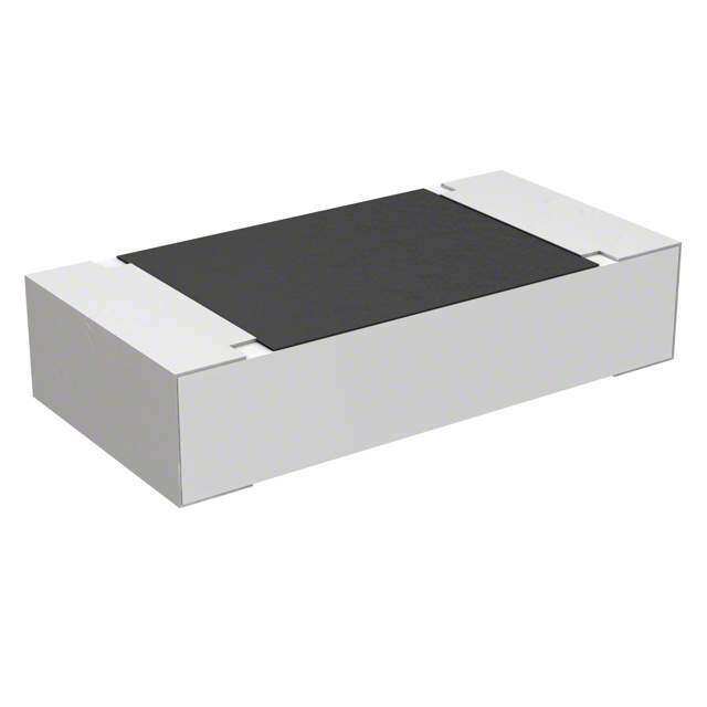
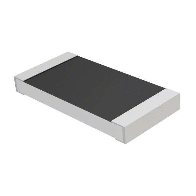
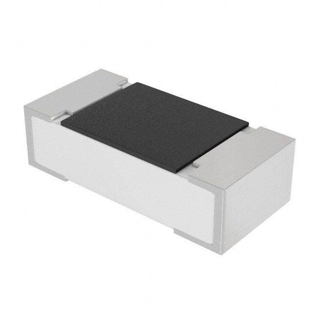
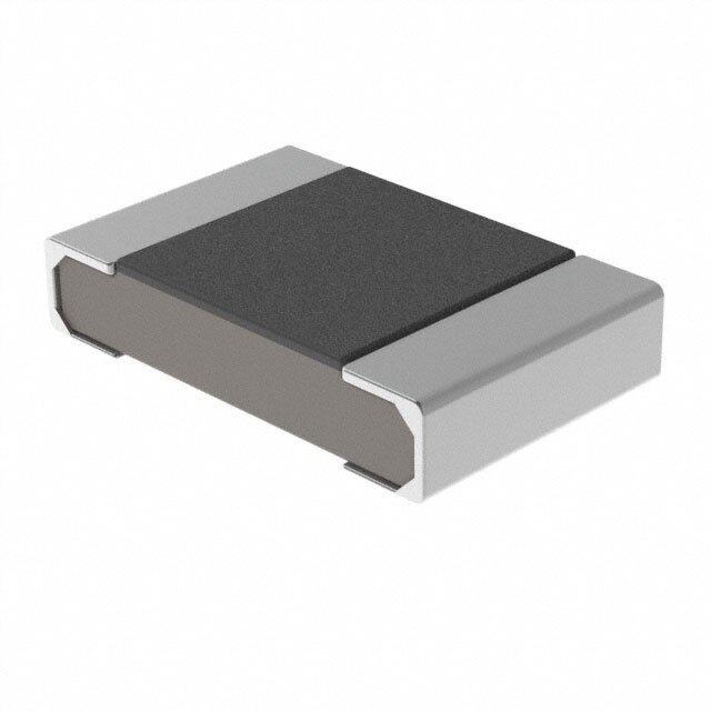
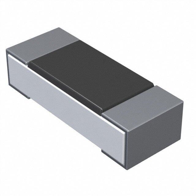
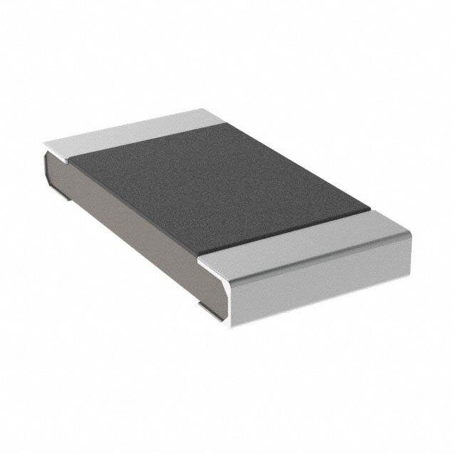
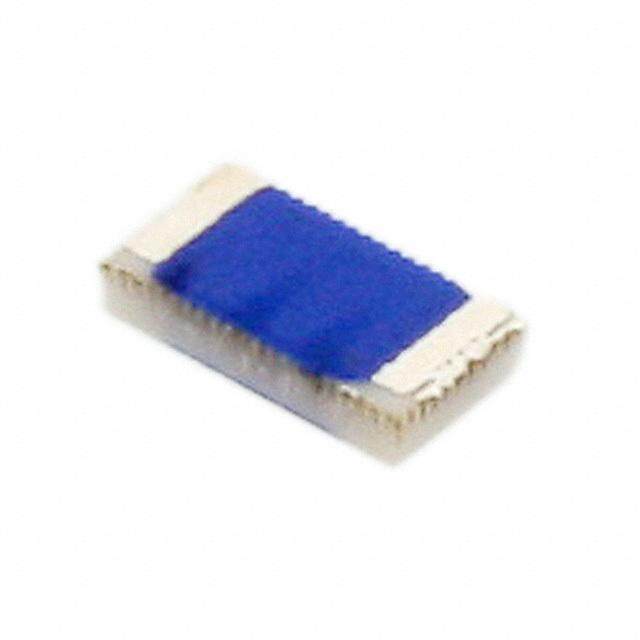
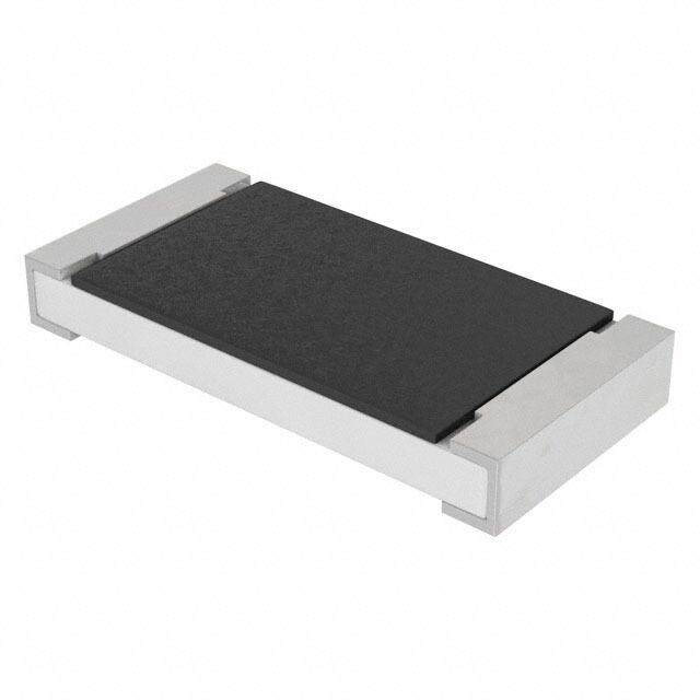
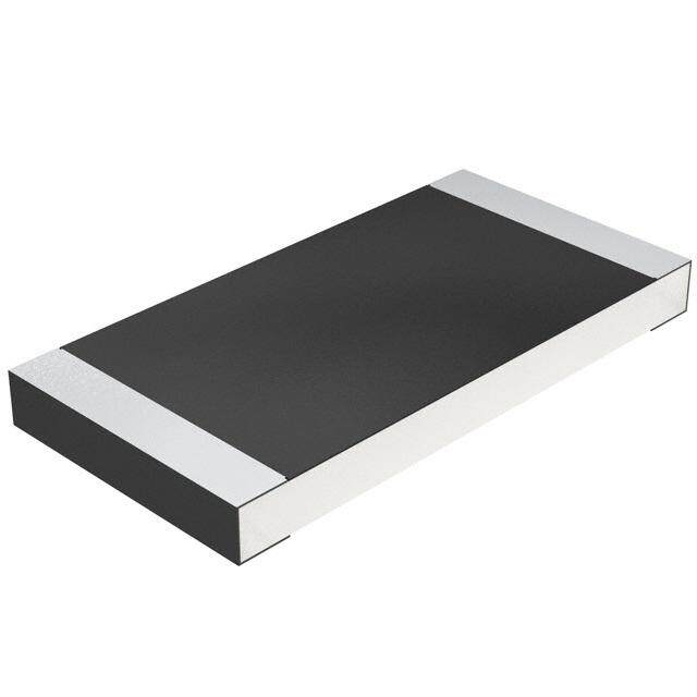
ICGOO电子元器件商城为您提供Y14730R02000B9R由Vishay Precision Group设计生产,在icgoo商城现货销售,并且可以通过原厂、代理商等渠道进行代购。 Y14730R02000B9R价格参考。Vishay Precision GroupY14730R02000B9R封装/规格:芯片电阻 - 表面安装, 20 mOhms ±0.1% 2W 金属箔 芯片电阻 非标准 电流感应,防潮 金属箔。您可以下载Y14730R02000B9R参考资料、Datasheet数据手册功能说明书,资料中有Y14730R02000B9R 详细功能的应用电路图电压和使用方法及教程。
Vishay Foil Resistors(Vishay Precision Group旗下分公司)生产的Y14730R02000B9R是一款高精度、低噪声的薄膜芯片电阻,属于表面贴装器件(SMD)。以下是该型号电阻的一些典型应用场景:

 1. 精密测量设备
   - Y14730R02000B9R具有极高的精度和稳定性,适合用于精密测量仪器,例如数字万用表、示波器、数据采集系统等。其低温度系数和低噪声特性能够确保测量结果的高度准确性。

 2. 医疗电子设备
   - 在医疗领域,如心电图机(ECG)、血压监测仪、呼吸机等设备中,需要使用高精度和稳定的电阻来保证信号处理的可靠性。该型号电阻能够满足这些设备对电气性能的严格要求。

 3. 航空航天与国防
   - 航空航天和国防领域的设备通常需要在极端环境下运行,而Y14730R02000B9R的高稳定性和抗振动能力使其非常适合应用于导航系统、雷达设备和卫星通信系统中。

 4. 工业自动化控制
   - 在工业自动化领域,如可编程逻辑控制器(PLC)、伺服驱动器和变频器中,该电阻可用于反馈电路、放大器和滤波器设计,以确保系统的精确控制和稳定性。

 5. 音频设备
   - 高保真音频设备(如专业音响、耳机放大器)对电阻的低噪声和线性度有较高要求。Y14730R02000B9R的优异性能可以改善音频信号的质量,减少失真。

 6. 电源管理
   - 在开关电源、稳压器和DC-DC转换器中,该电阻可用于电流检测、电压分压和反馈回路,提供高精度的控制功能。

 7. 测试与校准仪器
   - 校准仪器和参考标准设备需要极其稳定的电阻元件,Y14730R02000B9R的长期稳定性使其成为理想选择。

 总结
Y14730R02000B9R凭借其卓越的性能参数(如高精度、低温度系数、低噪声和高稳定性),广泛应用于对电气性能要求极高的领域。无论是消费电子还是高端工业设备,这款电阻都能提供可靠的解决方案。
| 参数 | 数值 |
| 产品目录 | |
| 描述 | RES 0.02 OHM 2W .1% 3637 |
| 产品分类 | |
| 品牌 | Vishay Foil Resistors (Division of Vishay Precision Group) |
| 数据手册 | |
| 产品图片 |
|
| 产品型号 | Y14730R02000B9R |
| rohs | 无铅 / 符合限制有害物质指令(RoHS)规范要求 |
| 产品系列 | CSM3637Z |
| 供应商器件封装 | - |
| 其它名称 | Y1473-.02CDKR |
| 其它有关文件 | |
| 功率(W) | 2W |
| 包装 | Digi-Reel® |
| 大小/尺寸 | 0.360" 长 x 0.370" 宽(9.14mm x 9.40mm) |
| 容差 | ±0.1% |
| 封装/外壳 | 3637 |
| 成分 | 金属箔 |
| 标准包装 | 1 |
| 温度系数 | ±5ppm/°C |
| 特性 | 电流感应, 防潮 |
| 特色产品 | http://www.digikey.com/cn/zh/ph/Vishay/foil-resistors.html |
| 电阻(Ω) | 0.02 |
| 端子数 | 4 |
| 高度 | 0.035"(0.89mm) |


- 商务部:美国ITC正式对集成电路等产品启动337调查
- 曝三星4nm工艺存在良率问题 高通将骁龙8 Gen1或转产台积电
- 太阳诱电将投资9.5亿元在常州建新厂生产MLCC 预计2023年完工
- 英特尔发布欧洲新工厂建设计划 深化IDM 2.0 战略
- 台积电先进制程称霸业界 有大客户加持明年业绩稳了
- 达到5530亿美元!SIA预计今年全球半导体销售额将创下新高
- 英特尔拟将自动驾驶子公司Mobileye上市 估值或超500亿美元
- 三星加码芯片和SET,合并消费电子和移动部门,撤换高东真等 CEO
- 三星电子宣布重大人事变动 还合并消费电子和移动部门
- 海关总署:前11个月进口集成电路产品价值2.52万亿元 增长14.8%


PDF Datasheet 数据手册内容提取
CSM3637Z Bulk Metal® Foil Technology Ultra High Precision, Current Sensing, Power Surface Mount, Metal Strip Resistor with Improved TCR to ±5 ppm/°C Max, Resistance Value from 3 m, Rated Power to 3 W FEATURES Resistance range: 3 m to 50 m Temperature coefficient of resistance (TCR): ± 5 ppm/°C maximum (- 55 °C to + 125 °C, + 25 °C ref.) INTRODUCTION Load life stability to ± 0.2 % (70 °C, 2000 h at The CSM3637Z is a low value current sense resistor, rated power) providing power and precision in a four terminal, surface Power rating: to 3 W (see table 1) mount configuration. Its all welded construction is made up of a Bulk Metal® resistive element with plated copper Resistance tolerance: ± 0.1 % terminations. Vishay Foil resistors are not restricted to standard values; specific “as required” values can be supplied at no extra There are many current sense resistors on the market. Until now the combination of very stable and precise resistors cost or delivery (e.g. 10.2345 m vs. 10 m) with extremely low TCR as much as ± 5 ppm/°C maximum, Short time overload: ± 0.1 % typical tight tolerance of ± 0.1 % and load life stability of ± 0.2 % Proprietary processing technique produces extremely low (2000 h, + 70 °C at rated power) was not easily available. resistance values with improved stability The key performance of the new CSM3637Z is its extremely All welded construction low TCR value. Solderable terminations These specifications are based on tests performed in accordance with methods prescribed by appropriate Very low inductance 0.5 nH MIL-PRF standards (MIL-PRF-55342 and MIL-PRF-49465). Excellent frequency response to 50 MHz The four terminal device separates the current leads from Low thermal EMF < 3 µV/°C (DC offset error, significant for the voltage sensing leads. This configuration eliminates the low values) effect of the lead wire resistance from points A to B and Maximum current: up to 31 A C to D. Four terminal (Kelvin) design: allows for precise and In addition a key feature of the CSM3637Z is its low thermal accurate measurements EMF design (very important for low ohmic value DC applications). The welded terminals make intimate contact Terminal finish: lead (Pb)-free or tin/lead alloy with the chip thereby minimizing temperature differentials. Prototype quantities available in just 5 working days Our application engineering department is available to or sooner. For more information, please contact advise and make recommendations. foil@vpgsensors.com For non-standard technical requirements and special For better performances please contact us applications, please contact: foil@vpgsensors.com FIGURE 1 - POWER DERATING CURVE + 70 °C R 100 I I %) wer ( 8600 o A B C D d P 40 e at 20 R V 0 Zin =~∞ - 65 - 50 - 25 0Amb2ie5nt Te5m0pera7t5ure 1(°0C0) 125 150 170 * This datasheet provides information about parts that are RoHS-compliant and/or parts that are non-RoHS-compliant. For example, parts with lead (Pb) terminations are not RoHS-compliant. Please see the information/tables in this datasheet for details. Document Number: 63208 For any questions, contact www.vishayfoilresistors.com Revision: 9-Mar-15 foil@vpgsensors.com 1
CSM3637Z ABOUT CSM3637Z (Low Ohm Value 3 m to 50 m) This new high-precision Bulk Metal® surface-mount Power conversion is protected from such interference in DC Metal Strip® resistor of 3 m to 50 m features an improved applications. load-life stability of ± 0.2 % at + 70 °C for 2000 h at rated The stability problems associated with analog circuits are power, an absolute TCR of ± 5 ppm/°C maximum from very pervasive, but knowledgeable selection of a few - 55 °C to + 125 °C, + 25 °C ref., and a tolerance of ± 0.1 %. high-quality resistors, networks, or trimming potentiometers Typical current sensing resistors exhibit 2000 hour load-life in critical locations can greatly improve circuit performance, changes more than 5 times greater than the CSM3637Z. The long-term application-related performance, as well as the improved resistance stability of the CSM Series makes it designer’s peace-of-mind. ideal for tightened-stability voltage division and precision Additionally, the overall system cost is often reduced when a current sensing applications in switching linear power knowledgeable designer concentrates costs in a few supplies, power amplifiers, measurement instrumentation, exceptionally stable components whose proven minimal- bridge networks, and medical and test equipment. deviation load and environmental stability can often eliminate Traditional Passive current sensors and shunts generate the necessity of additional compensating circuitry or heat under power, which changes their resistance, and thus temperature-controlling systems. The higher reliability and their voltage output. The CSM’s low absolute TCR of better overall system performances also achieve excellent ± 5 ppm/°C reduces errors due to temperature changes, product results in the field, enhancing market acceptance thus reducing a major source of uncertainty in current and product reputation. measurement. The CSM can withstand unconventional Designers often unnecessarily pay for tighter tolerances than environmental conditions, including the extremely high required simply to accommodate the resistance stability temperatures and radiation-rich environments of down-hole shifts they know to be imminent in an application due to the oil exploration and well logging, or the deep-sea underwater large application-related changes in the components they repeaters in cross-ocean communications. selected. Selection of a high-stability component like the The stability of the CSM3637Z can be further enhanced by CSM in these applications eliminates the need for shift post-manufacturing operations (PMO), such as temperature allowance due to “planned instability” and allows the use of cycling, short-time overload, and accelerated load life which looser initial tolerances than would be necessary with are uniquely applicable to Bulk Metal Foil Technology. current-sensing resistors based on other technologies. The device features a low thermal electromotive force (EMF) The Key Applications that is critical in many precision DC applications. The CSM’s Applications requiring accuracy and repeatability under all-welded construction is composed of a Bulk Metal resistive stress conditions such as the following: element with welded copper terminations, plated for soldering. The terminations make true ohmic contact with the Switching and linear power supplies resistive layer along the entire side of the resistive element, Precision current-sensing thereby minimizing temperature variations. Also, the resistor Power management systems element is designed to uniformly dissipate power without creating hot spots, and the welded terminations material is Feedback circuits compatible with the element material. Power amplifiers These design factors result in a very low thermal-EMF Measurement instrumentation (3 µV/°C) resistor because, in addition to the low thermal Precision instrumentation amplifiers EMF compatibility of the metals, the uniformity and thermal Medical and automatic test equipment efficiency of the design minimizes the temperature Satellites and aerospace systems differential across the resistor, thereby assuring low thermal EMF generation at the leads. This further reduces the Commercial and Military avionics “battery effect” exhibited by most current-sensing or Test and measurement equipment voltage-reference resistors. Thus, the parasitic voltage Electronic scales generated at the junction of two dissimilar metals, which is especially important in low-value DC current-sensing resistors, is minimized, while the pure current-to-voltage www.vishayfoilresistors.com For any questions, contact Document Number: 63208 2 foil@vpgsensors.com Revision: 9-Mar-15
CSM3637Z TABLE 1 - PERFORMANCE SPECIFICATIONS PARAMETER CSM3637Z Resistance Range 3 m to 50 m 3W (3m to 10m) Power Rating at 70 °C 2W (>10m to 50m) Maximum Current 31 A Tightest Tolerance ± 0.1 % Temperature Coefficient Maximum (- 55 °C to + 125 °C, + 25 °C ref.) ± 5 ppm/°C Thermal EMF < 3 µV/°C Operating Temperature Range - 65 °C to + 170 °C Weight (maximum) 0.29 g FIGURE 2 - DIMENSIONS AND IMPRINTING in inches (millimeters) CSM3637Z DIMENSIONS CSM3637Z LAND PATTERN (1) E1 I 1 H E 2 c A I 2 B d I b L W T a DIMENSIONS - TOLERANCES ± 0.010 (± 0.254) RESISTANCE RANGE (m) L W H T A B 3 to 50 0.360 (9.144) 0.370 (9.398) 0.025 (0.635) 0.086 (2.184) 0.061 (1.549) 0.032 (0.813) LAND PATTERN DIMENSIONS - TOLERANCES ± 0.003 (± 0.076) RESISTANCE RANGE (m) l b a c d 3 to 50 0.178 (4.52) 0.390 (9.91) - 0.116 (2.95) 0.066 (1.68) 0.024 (0.610) Note (1)White dots indicate top side of part for mounting purposes POWER METAL STRIP® CSM3637Z CONSTRUCTION 1. Resistive element 2. Copper terminal with solderable finish 3. Terminal-to-element weld 4. High temperature encapsulation Document Number: 63208 For any questions, contact www.vishayfoilresistors.com Revision: 9-Mar-15 foil@vpgsensors.com 3
CSM3637Z TABLE 2 - CSM3637Z PERFORMANCE SPECIFICATIONS MIL-PRF-49465B TYPICAL MAXIMUM TEST CONDITIONS R LIMITS R LIMITS R LIMITS - 55 °C to + 150 °C, 1000 cycles, Thermal Shock ± (0.5 % + 0.0005R) 0.1 % 0.3 % 15 min at each extreme Load Life Stability 2000 h, 70 °C at rated power ± (1.0 % + 0.0005R) 0.2 % 0.5 % Bias Humidity 85 °C, 85 % humidity, 10 % bias, 1000 h ± (0.5 % + 0.0005R) 0.05 % 0.2 % Short Time Overload 5 x rated power for 5 s ± (0.5 % + 0.0005R) 0.1 % 0.2 % High Temperature Exposure 1000 h, 170 °C ± (1.0 % + 0.0005R) 0.2 % 0.3 % Low Temperature Storage MIL-PRF-49465 ± (0.5 % + 0.0005R) 0.05 % 0.1 % MIL-STD-202, method 106, 0 % power, Moisture Resistance ± (0.5 % + 0.0005R) 0.02 % 0.05 % 7a and 7b not required Shock 100 g, 6 ms ± (0.1 % + 0.0005R) 0.02 % 0.05 % Vibration (10 Hz to 2000 Hz) 20 g ± (0.1 % + 0.0005R) 0.02 % 0.05 % Resistance to Soldering Heat 10 s to 12 s at + 260 °C ± (0.25 % + 0.0005R) 0.05 % 0.1 % Solderability MIL-STD-202 95 % coverage - Note • Measurement error 0.0005R per MIL-PRF-49465 TABLE 3 - GLOBAL PART NUMBER INFORMATION (1) NEW GLOBAL PART NUMBER: Y14730R05000E0R (preferred part number format) DENOTES PRECISION VALUE CHARACTERISTICS Y R = 0 = standard part, tin/lead termination 9 = standard part, lead (Pb)-free termination 1 to 999 = custom Y 1 4 7 3 0 R 0 5 0 0 0 E 0 R PRODUCT CODE RESISTANCE TOLERANCE PACKAGING 1473 = CSM3637Z B= ± 0.1% W= waffle pack C= ± 0.25 % R = tape and reel D= ± 0.5 % E = ± 0.2 % F = ± 1.0 % FOR EXAMPLE: ABOVE GLOBAL ORDER Y1473 0R05000 E 0 R: TYPE: CSM3637Z VALUE: 50 m ABSOLUTE TOLERANCE: ± 0.2 % TERMINATION: standard tin/lead PACKAGING: tape and reel HISTORICAL PART NUMBER: CSM3637Z 0R05 E B T (will continue to be used) CSM3637Z 0R05 E B T MODEL OHMIC VALUE ABS. TOLERANCE TERMINATION PACKAGING 0R05 = 0.05 B= ± 0.1% S = lead (Pb)-free T = tape and reel C= ± 0.25 % B= tin/lead W= waffle pack D= ± 0.5 % E= ± 0.2 % F = ± 1.0 % Note (1)For non-standard requests, please contact application engineering. www.vishayfoilresistors.com For any questions, contact Document Number: 63208 4 foil@vpgsensors.com Revision: 9-Mar-15
LLeeggaall DDiissccllaaiimmeerr NNoottiiccee Vishay Precision Group, Inc. DDiissccllaaiimmeerr ALL PRODUCTS, PRODUCT SPECIFICATIONS AND DATA ARE SUBJECT TO CHANGE WITHOUT NOTICE. Vishay Precision Group, Inc., its affiliates, agents, and employees, and all persons acting on its or their behalf (collectively, “VPG”), disclaim any and all liability for any errors, inaccuracies or incompleteness contained herein or in any other disclosure relating to any product. The product specifications do not expand or otherwise modify VPG’s terms and conditions of purchase, including but not limited to, the warranty expressed therein. VPG makes no warranty, representation or guarantee other than as set forth in the terms and conditions of purchase. To the maximum extent permitted by applicable law, VPG disclaims (i) any and all liability arising out of the application or use of any product, (ii) any and all liability, including without limitation special, consequential or incidental damages, and (iii) any and all implied warranties, including warranties of fitness for particular purpose, non-infringement and merchantability. Information provided in datasheets and/or specifications may vary from actual results in different applications and performance may vary over time. Statements regarding the suitability of products for certain types of applications are based on VPG’s knowledge of typical requirements that are often placed on VPG products. It is the customer’s responsibility to validate that a particular product with the properties described in the product specification is suitable for use in a particular application. You should ensure you have the current version of the relevant information by contacting VPG prior to performing installation or use of the product, such as on our website at vpgsensors.com. No license, express, implied, or otherwise, to any intellectual property rights is granted by this document, or by any conduct of VPG. The products shown herein are not designed for use in life-saving or life-sustaining applications unless otherwise expressly indicated. Customers using or selling VPG products not expressly indicated for use in such applications do so entirely at their own risk and agree to fully indemnify VPG for any damages arising or resulting from such use or sale. Please contact authorized VPG personnel to obtain written terms and conditions regarding products designed for such applications. Product names and markings noted herein may be trademarks of their respective owners. Copyright Vishay Precision Group, Inc., 2014. All rights reserved. Document No.: 63999 www.vpgsensors.com Revision: 15-Jul-2014 1