ICGOO在线商城 > XAN.M13.GLA.6G
 Datasheet下载
- 型号: XAN.M13.GLA.6G
- 制造商: LEMO
- 库位|库存: xxxx|xxxx
- 要求:
| 数量阶梯 | 香港交货 | 国内含税 |
| +xxxx | $xxxx | ¥xxxx |
查看当月历史价格
查看今年历史价格
XAN.M13.GLA.6G产品简介:
ICGOO电子元器件商城为您提供XAN.M13.GLA.6G由LEMO设计生产,在icgoo商城现货销售,并且可以通过原厂、代理商等渠道进行代购。 提供XAN.M13.GLA.6G价格参考以及LEMOXAN.M13.GLA.6G封装/规格参数等产品信息。 你可以下载XAN.M13.GLA.6G参考资料、Datasheet数据手册功能说明书, 资料中有XAN.M13.GLA.6G详细功能的应用电路图电压和使用方法及教程。
| 参数 | 数值 |
| 产品目录 | |
| 描述 | CONN INLINE PLUG 13PIN SLD CUP环形推拉式连接器 13POS ML PLUG 4A GRAY COLLET |
| 产品分类 | |
| 品牌 | LEMO |
| 产品手册 | |
| 产品图片 |
|
| rohs | 符合RoHS无铅 / 符合限制有害物质指令(RoHS)规范要求 |
| 产品系列 | 环形推拉式连接器,LEMO XAN.M13.GLA.6GXP |
| 数据手册 | |
| 产品型号 | XAN.M13.GLA.6G |
| 产品培训模块 | http://www.digikey.cn/PTM/IndividualPTM.page?site=cn&lang=zhs&ptm=25888 |
| 产品种类 | 环形推拉式连接器 |
| 产品类型 | Connectors |
| 侵入防护 | IP50 - 防尘 |
| 其它名称 | 1124-1284 |
| 包装 | 散装 |
| 商标 | LEMO |
| 商标名 | REDEL |
| 外壳尺寸-插件 | M13 |
| 外壳尺寸,MIL | - |
| 外壳材料,镀层 | 砜 |
| 外壳材质 | Hybrid |
| 外壳类型 | Plug |
| 安装类型 | 自由悬挂 |
| 工作温度 | -50°C ~ 170°C |
| 朝向 | N(正常型) |
| 标准包装 | 1 |
| 特性 | - |
| 特色产品 | http://www.digikey.com/product-highlights/cn/zh/lemo-redel-xp-series-connectors/1139 |
| 电压-额定 | - |
| 电流额定值 | 4 A |
| 端接 | 焊杯 |
| 端接类型 | Solder |
| 系列 | XP |
| 紧固类型 | 推挽式 |
| 视频文件 | http://www.digikey.cn/classic/video.aspx?PlayerID=1364138032001&width=640&height=455&videoID=1381285120001http://www.digikey.cn/classic/video.aspx?PlayerID=1364138032001&width=640&height=455&videoID=1381254954001http://www.digikey.cn/classic/video.aspx?PlayerID=1364138032001&width=640&height=455&videoID=1384169739001 |
| 触头镀层 | 金 |
| 触头镀层厚度 | - |
| 触点数量 | 13 |
| 触点类型 | Pin (Male) |
| 连接器类型 | Plug |
| 配套产品 | /product-detail/zh/XRN.M13.GLL.6GZ/1124-1300-ND/2786402/product-detail/zh/XRN.M13.GLL.6G/1124-1299-ND/2786401/product-detail/zh/XRN.M13.GLL.6A/1124-1298-ND/2786400/product-detail/zh/XKN.M13.GLLG/1124-1292-ND/2786394/product-detail/zh/XKN.M13.GLLA/1124-1291-ND/2786393 |
| 针脚数 | 13 |
| 额定电流 | 4A |


- 商务部:美国ITC正式对集成电路等产品启动337调查
- 曝三星4nm工艺存在良率问题 高通将骁龙8 Gen1或转产台积电
- 太阳诱电将投资9.5亿元在常州建新厂生产MLCC 预计2023年完工
- 英特尔发布欧洲新工厂建设计划 深化IDM 2.0 战略
- 台积电先进制程称霸业界 有大客户加持明年业绩稳了
- 达到5530亿美元!SIA预计今年全球半导体销售额将创下新高
- 英特尔拟将自动驾驶子公司Mobileye上市 估值或超500亿美元
- 三星加码芯片和SET,合并消费电子和移动部门,撤换高东真等 CEO
- 三星电子宣布重大人事变动 还合并消费电子和移动部门
- 海关总署:前11个月进口集成电路产品价值2.52万亿元 增长14.8%


PDF Datasheet 数据手册内容提取
PLASTIC CONNECTORS ® ®
Precision modular connectors to suit your application Since its creation in Switzerland in 1946 the LEMO Group has been recognized as a global leader of circular Push-Pull connectors and connector solutions. Today LEMO and its affiliated companies, REDEL and COELVER, are active in more than 80 countries with the help of over 40 subsidiaries and distributors. Over 5’000 REDEL connectors The modular design of the REDEL range provides over 5’000 connectors from ø 14 mm to ø 21 mm, capable of handling cable diameters up to 9.5 mm and up to 32 contacts. This vast portfolio enables you to select the ideal connector configuration to suit almost any specific requirement in most markets, including medical devices, test and measurement instruments, machinery, audio video broadcast, telecommunica- tions and military. REDEL’s Push-Pull Self-Latching Connection System This self-latching system is renowned worldwide for its easy and quick mating and unmating features. It provides absolute security against vibration, shock or pull on the cable, and facilitates operation in a very limited space. The REDEL self-latching system allows the connector to be mated by simply pushing Fv 7 N the plug axially into the socket. Fv: average latching force (without contact) Once firmly latched, connection cannot be broken by pulling on the cable or any other component part other than the outer release F 110 N a sleeve. Fa: average retention force (without contact) When required, the connector is disengaged by a single axial pull on the outer release sleeve. This first disengages the latches and F 9 N d then withdraws the plug from the socket. Fd: average unmating force (without contact) UL Recognition ® REDEL connectors are recognized by the Underwriters Laboratories (UL). The approval of the complete system (REDEL connector, cable and your equipment) will be easier because REDEL connectors are approved. CE Marking CE marking means that the appliance or equipment bearing it complies with the protection requirements of one or several European safety directives. CE marking applies to complete products or equipment, but not to electromechanical components, such as connectors. RoHS REDEL connector specifications exceed the requirements of the RoHS directives (2002/95/EC) of the European Parliament and the latest amendments. This directive specifies the restrictions of the use of hazardous substances in electrical and electronic equipment marketed in Europe. LEMO guarantees that its connectors are free of mercury, cadmium, lead, hexavalent chromium and polybromide biphenyl (PBB), polybromide diphenyl ether (PBDE), or DecaBDE. Cover picture:PET-IRM scanner installed in Hôpitaux Universitaires de Genève (Switzerland). www.lemo.com
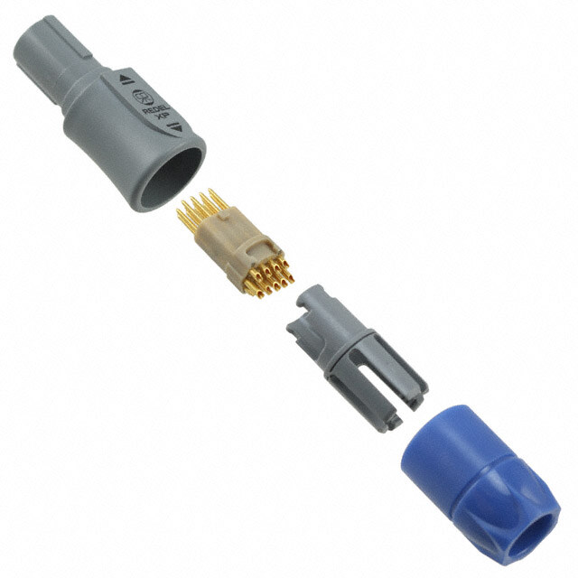
Exploded view of the REDEL XP Straight plug backnut cable collet insulator + contacts shell Straight plug with bend relief backnut for bend relief cable collet insulator + contacts shell a bend relief Fixed socket collet nut notched nut insulator + contacts shell front nut Free socket backnut cable collet insulator + contacts shell www.lemo.com 1
XP Series The REDEL XP connectors are plastic Push-Pull connectors. These circular plastic connectors are especially adapted for applications such as medical electronics and test & measurement. The XP series offer additional features: the latch sleeve is recessed into the connector body ensuring greater shock resistance of the product. The complete connector can be assembled from spare parts (even the contact configuration) therefore offering good flexibility in stock keeping. The outer shell in Proprietary sulfone enables extensive sterilisation cycles of the product. A large choice of bend relief is available in different colour and size. REDEL XP series connectors are not compatible with the REDEL 1P or 2P series. Features & Benefits Applications –Plastic shell made of Proprietary sulfone – Medical electronics –Blind mating, scoop proof –Test & measurement –Extended resistance to sterilisation –Industrial electronics –Enhanced ergonomics «hand grip» –Increased resistance to shock –New patented Push-Pull system –UL recognized (file E119802) Standard models Straight plugs Fixed sockets Free sockets XR● XA● XL● XA● XK● XR● XK● 2 www.lemo.com
Part numbering system X .M . . Plug X A N . M 1 3 . G L A . 6 G Variant Z= cable collet and nut for fitting a bend relief Collet nut colour table: (page 7) Model: (pages 4-5) G= grey N = black A = blue R = red Keying: (page 6) J = yellow V = green B = white Contact configuration (page 6) Collet: 3 = (cable ø 2.5 mm - 3.9 mm) 5 = (cable ø 4.0 mm - 5.2 mm) Number of contacts: (page 6) 6 = (cable ø 5.3 mm - 6.5 mm) 7 = (cable ø 6.6 mm - 7.5 mm) Outershell colour: G = grey N = black B = white Contact type: (page 7) A= male to solder L = female to solder 1) Insulator: L = PEEK C= male to crimp M= female to crimp 1) Free socket X R N . M 1 3 . G L L . 6 G Variant Z= cable collet and nut for fitting a bend relief Collet nut colour table: (page 7) Model: (pages 4-5) G= grey N = black A = blue R = red Keying: (page 6) J = yellow V = green B = white Contact configuration (page 6) Collet: 3 = (cable ø 2.5 mm - 3.9 mm) 5 = (cable ø 4.0 mm - 5.2 mm) Number of contacts: (page 6) 6 = (cable ø 5.3 mm - 6.5 mm) 7 = (cable ø 6.6 mm - 7.5 mm) Outershell colour: G = grey N = black B = white Contact type: (page 7) A= male to solder 1) L = female to solder Insulator: L = PEEK C= male to crimp 1) M= female to crimp Fixed socket X K N . M 1 3 . G L L G Front nut colour table: (page 7) Model: (pages 4-5) G= grey N = black A = blue R = red Keying: (page 6) J = yellow V = green B = white Contact configuration (page 6) Contact type: (page 7) A= male to solder 1) C= male to crimp 1) Number of contacts: (page 6) D= male to print 1) L = female to solder M= female to crimp N= female to print Outershell colour: G = grey V = female 90° for print N = black B = white Insulator: L = PEEK XAN.M13.GLA.6G Straight plug with cable collet and alignment key (N), multipole type with 13 male contacts to solder, grey Proprietary sulfoneshell, PEEK insulator, collet for max cable ø 6.5 mm and grey collet nut. XRN.M13.GLL.6GFree socket with cable collet and alignment key (N), multipole type with 13 female contacts to solder, grey Proprietary sulfoneshell, PEEK insulator, collet for max cable ø 6.5 mm and grey collet nut. XKN.M13.GLLG Fixed socket with two nuts and alignment key (N), multipole type with 13 female contacts to solder, grey Proprietary sulfoneshell, PEEK insulator and grey plastic front nut. Note:1)contacts delivered only with S or T keying (inverted contacts). www.lemo.com 3
Standard models (IP50) X .M . . Fixed socket Straight plug 6 4 2 3 1 5 5 4 2 1 6 3 1 Outershell 1 Outershell 2 Insulator 2 latch sleeve 3 Female contact 3 Backnut 4 Notched nut 4 Insulator 5 Front nut 5 Contact 6 Collet nut 6 Cable collet Characteristics Value Standards Characteristics Value Standards Average retention force when Endurance (latching) > 1000 cycles IEC 60512-5 test 9a pulling on the cable 1N = 0.102 kg 110 IEC 60512-8 test 15f Working temperature range -50/+170°C – (Proprietary sulfone) Cable retention force (depends on cable construction) 1N = 0.102 kg ~130 IEC 60512-9 test 17c XAN Straight plug, key (N) or keys (P, S and T), with cable collet Cable ø Part Number min max XAN.M(cid:129)(cid:129).GLA.3G 2.5 3.9 XAN.M(cid:129)(cid:129).GLA.5G 4.0 5.2 XAN.M(cid:129)(cid:129).GLA.6G 5.3 6.5 XAN.M(cid:129)(cid:129).GLA.7G 6.6 7.5 Note:replace (cid:129).(cid:129) by contact configuration (see page 6). ~46 5 6. 1 ø XAN Straight plug, key (N) or keys (P, S and T), with cable collet and nut for fitting a bend relief Cable ø Part Number min max XAN.M(cid:129)(cid:129).GLA.3GZ 2.5 3.9 XAN.M(cid:129)(cid:129).GLA.5GZ 4.0 5.2 XAN.M(cid:129)(cid:129).GLA.6GZ 5.3 6.5 XAN.M(cid:129)(cid:129).GLA.7GZ 6.6 7.5 Note:replace (cid:129).(cid:129) by contact configuration (see page 6). ~48.0 The bend relief must be ordered separately (see page 10). 5 6. 1 ø XLN Fixed socket, key (N) or keys (P, S and T), nut fixing Contact a Part Number Solder Crimp 23.5 a max (mm) a (mm) 5.2 XLN.M(cid:129)(cid:129).GLLG 2.2 0 Note:replace (cid:129).(cid:129) by contact configuration (see page 6). M14 x 1 ø 18.5 S12.5 7.5 maxi Note:all dimensions are in millimeters. 4 www.lemo.com
X .M . . XKN Fixed socket, key (N) or keys (P, S and T) with two nuts (back panel mounting) Contact a Part Number Solder Crimp 23.5 a max (mm) a (mm) 3 4 XKN.M(cid:129)(cid:129).GLLG 2.2 0 Note:replace (cid:129).(cid:129) by contact configuration (see page 6). M14 x 1 ø 18.5 S12.5 8.5 maxi XKN Fixed socket, key (N) or keys (P, S and T) with two nuts (back panel mounting) and with straight print contact Contact a Part Number Solder Crimp 23.5 a max (mm) a (mm) 3 4 XKN.M(cid:129)(cid:129).GLNG 4.1 0 Note:replace (cid:129).(cid:129) by contact configuration (see page 6). M14 x 1 ø 18.5 S12.5 8.5 maxi XRN Free socket, key (N) or keys (P, S and T), with cable collet Cable ø Part Number min max XRN.M(cid:129)(cid:129).GLL.3G 2.5 3.9 XRN.M(cid:129)(cid:129).GLL.5G 4.0 5.2 XRN.M(cid:129)(cid:129).GLL.6G 5.3 6.5 XRN.M(cid:129)(cid:129).GLL.7G 6.6 7.5 Note:replace (cid:129).(cid:129) by contact configuration (see page 6). ~44.7 7 5. 1 ø XRN Free socket, key (N) or keys (P, S and T), with cable collet and nut for fitting a bend relief Cable ø Part Number min max XRN.M(cid:129)(cid:129).GLL.3GZ 2.5 3.9 XRN.M(cid:129)(cid:129).GLL.5GZ 4.0 5.2 XRN.M(cid:129)(cid:129).GLL.6GZ 5.3 6.5 XRN.M(cid:129)(cid:129).GLL.7GZ 6.6 7.5 Note:replace (cid:129).(cid:129) by contact configuration (see page 6). The bend relief must be ordered separately (see page 10). ~46.7 7 5. 1 ø Note:all dimensions are in millimeters. www.lemo.com 5
Alignment key X .M . . Verify the third digit of the part number in order to select the right keying. The standard keying is «N» coded. 0 0 0 0 Keying (plug front view) 30° 60° 50° 90° Reference N P S T Contact type for plug male male female female Contact type for socket female female male male Insert configuration X .M . . Male solder contacts Female solder contacts Cotynptaect Solder Crimp ø A ht) m) m) g m m ai ( ( Male crimp conø Atacts13 46 Female crimp con46tacts 13 Reference Number of contacts Contact ø A (mm) 4)Solder bucket ø (mm) 4)Crimp bucket ø (mm) AWG max-min Solder / Crimp / Print (str Print (elbow) 1)Test voltage (kV rms)Contact-contact 2)Air clearance min(mm)Creepage distance min3) Rated current (A) 1)Test voltage (kV rms)Contact-contact 2)Air clearance min(mm)Creepage distance min3) Rated current (A) 184) M04 4 1.3 1.10 1.40 20 (cid:129) (cid:129) 1.60 0.95 11.5 1.80 1.35 11.5 22 20 M06 6 0.9 0.80 1.10 22 (cid:129) (cid:129) 1.50 0.95 8.5 1.90 1.35 8.5 24 20 M08 8 0.9 0.80 1.10 22 (cid:129) (cid:129) 1.50 0.75 5.0 1.50 1.1 5.0 24 224) M10 10 0.7 0.80 0.80 24 (cid:129) (cid:129) 1.16 0.70 4.2 1.53 1.1 4.2 ole 26 p Multi 224) M13 13 0.7 0.80 0.80 24 (cid:129) (cid:129) 1.05 0.50 4.0 1.30 0.9 4.0 26 28 M16 16 0.5 0.45 0.45 30 (cid:129) – 0.75 0.45 3.0 1.35 0.8 3.0 32 28 M18 18 0.5 0.45 0.45 30 (cid:129) – 0.74 0.47 2.5 1.16 0.8 2.5 32 28 M22 22 0.5 0.45 0.45 30 (cid:129) – 0.60 0.40 2.0 1.30 0.8 2.0 32 Note:1)depending on specific application and related standard, more restrictive operating voltage may apply. We suggest operating voltage = 1/3 test voltage, see page 15. 2)shortest distance in air between two conductive parts. 3)shortest distance along the surface of the insulating material between two conductive parts. 4)for a given AWG, the diameter of some stranded conductor design is larger than the solder cup diameter (see page 14). 6 www.lemo.com
Outer shell material X .M . . Material ef. Colour Temperature R G Grey Proprietary sulfone N Black -50° / +170°C B White Note:adapted for sterilisation satured steam (120°C or 134°C). Contact type X .M . . Select the type of contact: solder or crimp? When should I use crimp rather than solder contacts ? Plug Type Male Female Soldering solder A L1) (cid:129) recommended for small volumes crimp C M1) (cid:129) requires little amount of tooling (soldering iron) (cid:129) requires more time Socket Type Male Female Crimping solder A1) L (cid:129) recommended for large volumes crimp - M (cid:129) no heat is required to make the connection print D1) N (cid:129) for contacts with high density print 90° - V (cid:129) for use in high temperature environment (max. 170°C) Note:1)only for S or T keying. (cid:129) requires extra tooling (crimping tools) Colour coding X .M . . Colours grey blue yellow black red green white Reference G A J N R V B Note:the RAL colours are indicative and depend on raw material and production process. RAL code 7001 5015 1016 9005 3020 6019 9003 Colour may differ. Easy identification with the assistance of colour coding. Outershell is only available in grey, black or white. www.lemo.com 7
Accessories XAN / XLN Insulator and male or female crimp contacts Kit contact part Kit contact part Contact nb. of ø contact number number configuration contacts (mm) Male Female M04 4 1.3 XAN.M04.ZLC XLN.M04.ZLM M06 6 0.9 XAN.M06.ZLC XLN.M06.ZLM M08 8 0.9 XAN.M08.ZLC XLN.M08.ZLM M10 10 0.7 XAN.M10.ZLC XLN.M10.ZLM male / black marking female / black marking M13 13 0.7 XAN.M13.ZLC XLN.M13.ZLM M16 16 0.5 XAN.M16.ZLC XLN.M16.ZLM M18 18 0.5 XAN.M18.ZLC XLN.M18.ZLM M22 22 0.5 XAN.M22.ZLC XLN.M22.ZLM XAN / XLN Insulator with male or female solder contacts Kit contact part Kit contact part Contact nb. of ø contact number number configuration contacts (mm) Male Female M04 4 1.3 XAN.M04.ZLA XLN.M04.ZLL M06 6 0.9 XAN.M06.ZLA XLN.M06.ZLL M08 8 0.9 XAN.M08.ZLA XLN.M08.ZLL M10 10 0.7 XAN.M10.ZLA XLN.M10.ZLL male / black marking female / black marking M13 13 0.7 XAN.M13.ZLA XLN.M13.ZLL M16 16 0.5 XAN.M16.ZLA XLN.M16.ZLL M18 18 0.5 XAN.M18.ZLA XLN.M18.ZLL M22 22 0.5 XAN.M22.ZLA XLN.M22.ZLL XAl.100.lZZ Plug outershell kit (no contacts) Part Number Colours ~36 XA(cid:129).100.GZZ grey XA(cid:129).100.BZZ white XA(cid:129).100.NZZ black Note:replace (cid:129) by alignment key (N, P, S or T). XRl.200.ll Free socket outershell kit (no contacts) Part Number Colours ~35 XR(cid:129).200.RG grey XR(cid:129).200.RB white XR(cid:129).200.RN black Note:replace (cid:129) by alignment key (N, P, S or T). XLl.200.lZZl Socket outershell kit (nut fixing), (no contacts) Part Number Colours 23.5 XL(cid:129).200.GZZG grey XL(cid:129).200.BZZB white 8.5 XL(cid:129).200.NZZN black 1 ø Note:replace (cid:129) by alignment key (N, P, S or T). 8 www.lemo.com
XKl.200.lZZl Socket outershell kit (with two nuts), (no contacts) Part Number Colours 23.5 XK(cid:129).200.GZZG grey XK(cid:129).200.BZZB white 8.5 XK(cid:129).200.NZZN black 1 ø Note:replace (cid:129) by alignment key (N, P, S or T). XAN Collet Cable ø (mm) Part Number min. max. 21.5 XAN.739.RG 2.5 3.9 XAN.752.RG 4.0 5.2 8 9. XAN.765.RG 5.3 6.5 ø ax XAN.775.RG 6.6 7.5 m XAM.130.ll Nut for fitting a GMA.1B bend relief Part Number Colours 20.3 XAM.130.RG grey XAM.130.RB white ø 10 ø 12.5 NXoAtMe:.1o3n0ly. RfoNr XA(cid:129), XR(cid:129) mobdlealcsk. XLN Notched nut 18.5 Part Number Colours M14 x 1 4 XLN.240.RG grey Note: all dimensions are in millimeters. XLN Collet nut M11 x 0.75 Part Number Colours 4.5 XLN.230.RG grey 12.5 XLN Plastic front nut for XLlmodels Part Number Colours 18.5 XLN.220.RG grey M14 x 1 XLN.220.RB white 5.2 XLN.220.RR red XLN.220.RN black XLN.220.RJ yellow XLN.220.RA blue XLN.220.RV green www.lemo.com 9
XKN Plastic front nut for XKlmodels Part Number Colours 18.5 XKN.220.RG grey M14 x 1 XKN.220.RB white 4 XKN.220.RR red XKN.220.RN black XKN.220.RJ yellow XKN.220.RA blue XKN.220.RV green GMA.1B Bend relief A bend relief absorbs the angular force that may be exerted on cables. These are designed for plugs and free sockets with cable col- let and nut. The Colours of these bend reliefs are not identical to the RAL coulours of the socket’s front nut. L A ø Dimensions (mm) Temperature range Reference Colours Part Number Bend relief Cable ø Material A L max. min. in dry atmosphere in water steam A blue GMA.1B.025.DG 2.5 30 2.9 2.5 B white GMA.1B.030.DG 3.0 30 3.4 3.0 G grey GMA.1B.035.DG 3.5 30 3.9 3.5 Desmopan J yellow 786 GMA.1B.040.DG 4.0 30 4.4 4.0 Polyurethane -40°C, +80°C – M brown GMA.1B.045.DG 4.5 30 4.9 4.5 elastomer N black GMA.1B.054.DG 5.4 30 6.0 5.4 R red GMA.1B.065.DG 6.5 30 7.0 6.5 S orange GMA.1B.025.RG 2.5 34 2.9 2.5 V green GMA.1B.030.RG 3.0 34 3.4 3.0 Note:the selection of pigments, which should GMA.1B.035.RG 3.5 34 3.9 3.5 remain stable at high temperature, is limited GMA.1B.040.RG 4.0 34 4.4 4.0 eSlaislictoomneer -60°C, +200°C +140°C bcoy ltohuer sn ewwil lr ebgeu ala tsiohnasd.e F doirf ftehrise nret afrsoomn, tshoomsee GMA.1B.045.RG 4.5 34 5.0 4.5 VMQ used for Desmopan bend reliefs. The selected solutions represent the best pos- GMA.1B.051.RG 5.1 34 5.6 5.1 sible compromise. GMA.1B.057.RG 5.7 34 6.2 5.7 GMA.1B.063.RG 6.3 34 7.0 6.3 Note:the last letter «G» of the part number indicates a grey colour, see the adjacent table and replace letter «G» by the letter of the colour required. All dimensions are in millimeters. 10 www.lemo.com
Tooling XOP.019.HN Spanners with notch for securing XOB.186.GN Spanners for nut XLN.220Rl the notched nut XOB.187.GN Spanners for nut XKN.220Rl 30 ø 20 7 6. 7 28 Material: Black polyamide. For notched nut XLN.240.RG. Material: Black polyamide DPC.91.701.V Crimping tool XOE Positioners for crimp contacts male female DCF Automatic extraction tools for crimp contacts Positioner part number Part number extractor Contact ø Conductor Selector No Configuration (mm) AWG Setting Male contact Female contact Male contact Female contact M04 1.3 18-20 XOE.130.VC XOE.130.VM 6-5-5 DCF.93.131.4LT DCF.93.131.4LT M06/M08 0.9 20-22-24 XOE.090.VC XOE.090.VM 6-5-5 DCF.93.090.4LT DCF.93.090.4LT M10/M13 0.7 22-24-26 XOE.070.VC XOE.070.VM 6-5-5 DCF.93.070.4LT DCF.93.070.4LT M16/M18/M22 0.5 28-30-32 XOE.050.VC XOE.050.VM 4-3-3 DCF.91.050.2LT1) DCF.91.050.2LT1) Note: the variance in conductor stranding diameter for the minimum AWG is such that some can have a cross section which is not sufficient to guarantee crimping as per IEC 60352-2 standard. 1)With this extractor, the user must remove the insulator from the outer shell. All dimensions are in millimeters. www.lemo.com 11
Panel hole For XLland XKl 12.6 ± 0.05 1 0.0 + 0 4. ø 1 23.5 min. Note:Socket mounting nut torque = 1 Nm. All dimensions are in millimeters. PCB drilling pattern For straight contacts 5 3 2.3 0.8 2.4 2.65 1. 2.1 1.1 2.1 2.3 0.8 2.4 2.65 1.35 2.1 1.1 2.1 4 x ø 0.8+00.1 1.1 1.1 6 x ø 0.8+00.1 1.2 1.2 8 x ø 0.8+00.1 1.5 1.5 10 x ø 0.8+00.1 1.5 1.5 M04 M06 M08 M10 2 1.78 87 1.6 1.3 65 1.3 1.6 0.8 1.6 1.32 0.66 1.3 1.97 0. 0. 4 1.7 66 13 x ø 0.81.78+00.1 1.65 1.1.665 16 x ø 0.61.3+00.1 1.4 1.1.34 18 x ø 0.61.6+00.1 10.7.65 0.615.1.67 22 x ø 0.61.32+00.1 0.1.801.67 0.6171.32.81 1.97 M13 M16 M18 M22 Note:all dimensions are in millimeters 12 www.lemo.com
Assembly instructions Solder contacts / Crimp contacts ➀ ➁ ➂ ➄ ➅ ➆ 1.Slide the collet nut ➀and then the collet ➁onto the cable. L Dimensions (mm) Configuration Solder contacts Crimp contacts L T L T M04 11.5 3.5 15.0 3.5 M06, M08 13.0 3.0 15.0 3.5 M10, M13 13.0 3.0 15.0 3.5 M16 to M22 12.5 2.5 14.5 2.5 2.Strip the cable according to the lengths given in the table. Tin the conductors. T 3. Solder conductors into contacts, starting with the center contacts, making sure that neither solder nor flux gets onto the insulator or cable insulation. solder/crimp Fix the appropriate positioner in the crimping tool. Set selector to the number corresponding to the conductor AWG as indicated on the positioner label. Fit conductor into contact and make sure it is visible through the ins- pection hole in the crimp barrel. Slide conductor-contact com- bination into the open crimping tool; make sure that the contact is fully pushed into the positioner. Close the tool. Remove from crimping tool and check that conductor is secure in contact and shows in inspection hole. 4.Slide the collet ➁ forward and locate both tags ➂ in the slots ➄on the insulator ➅. Push collet ➁ and insulator ➅ assembly into the shell ➆ whilst turning it to ensure that the tag ➂ locates in the inside slot of the shell. 5. Slide collet nut ➀over collet ➁ and tighten the collet nut ➀ to the maximum torque of 0.3 Nm. – Socket mounting nut torque = 1 Nm. www.lemo.com 13
Technical tables Table of American Wire Gauge Table of wire gauges according to IEC-60228 standard Construction ø wire max Wire section AWG Strand AWG/ (mm) (in) (mm2) (sq in) Coxn ød u(mctmor) no M(maxm ø) M(ainx) ø S(mecmtio2)n S(seqc tiino)n nb strand 0 259 24 11.277 0.444 52.90 0.0820 196x0.40 7.50 0.295 25.00 0.0387 1 817 30 9.702 0.382 41.40 0.0641 7x2.14 6.10 0.240 25.00 0.0387 2 259 26 8.89 0.35 33.20 0.0514 125x0.40 6.00 0.236 16.00 0.0248 4 133 25 6.9596 0.274 21.5925 0.0335 7x1.72 4.90 0.192 16.00 0.0248 6 133 27 5.5118 0.217 13.5885 0.0211 1x4.50 4.50 0.177 16.00 0.0248 8 168 30 4.4450 0.175 8.5127 0.0132 80x0.40 4.70 0.155 10.00 0.0155 8 133 29 4.3942 0.173 8.6053 0.0133 7x1.38 3.95 0.155 10.00 0.0155 10 105 30 3.3020 0.13 5.3204 0.0082 1x3.60 3.60 0.141 10.00 0.0155 10 37 26 2.9210 0.115 4.7397 0.0073 84x0.30 3.70 0.145 6.00 0.0093 10 1 10 2.6162 0.103 5.2614 0.0082 7x1.50 3.15 0.124 6.00 0.0093 12 37 28 2.3114 0.091 2.9765 0.0046 1x2.76 2.76 0.108 6.00 0.0093 12 19 25 2.3622 0.093 3.0847 0.0048 56x0.30 2.80 0.110 4.00 0.0062 121) 7 20 2.5400 0.10 3.6321 0.0056 7x0.86 2.58 0.098 4.00 0.0062 12 1 12 2.0828 0.082 3.3081 0.0051 1x2.25 2.25 0.082 4.00 0.0062 14 41 30 2.0574 0.081 2.0775 0.0032 50x0.25 2.15 0.084 2.50 0.0038 14 19 27 1.8542 0.073 1.9413 0.0030 7x0.68 2.04 0.080 2.50 0.0038 141) 7 22 2.0828 0.082 2.2704 0.0035 1x1.78 1.78 0.070 2.50 0.0038 14 1 14 1.6510 0.065 2.0820 0.0032 30x0.25 1.60 0.062 1.50 0.0023 161) 65 34 1.5748 0.062 1.3072 0.0020 7x0.52 1.56 0.061 1.50 0.0023 16 26 30 1.5748 0.062 1.3174 0.0020 1x1.4 1.40 0.055 1.50 0.0023 16 19 29 1.4986 0.059 1.2293 0.0019 32x0.20 1.35 0.053 1.00 0.0015 161) 7 24 1.5494 0.061 1.4330 0.0022 7x0.43 1.29 0.050 1.00 0.0015 16 1 16 1.3208 0.052 1.3076 0.0020 1x1.15 1.15 0.045 1.00 0.0015 181) 65 36 1.2700 0.05 0.8234 0.0013 42x0.15 1.20 0.047 0.75 0.0011 181) 42 34 1.2700 0.05 0.8447 0.0013 28x0.20 1.15 0.045 0.75 0.0011 18 19 30 1.3208 0.052 0.9627 0.0015 1x1.0 1.00 0.039 0.75 0.0011 18 16 30 1.2954 0.051 0.8107 0.0013 28x0.15 0.95 0.037 0.50 7.7x10⁻⁴ 18 7 26 1.2700 0.05 0.8967 0.0014 16x0.20 0.90 0.035 0.50 7.7x10⁻⁴ 18 1 18 1.0414 0.041 0.8229 0.0013 1x0.80 0.80 0.031 0.50 7.7x10⁻⁴ 201) 42 36 1.0160 0.04 0.5320 8.2x10⁻⁴ 7x0.25 0.75 0.029 0.34 5.2x10⁻⁴ 20 19 32 1.0414 0.041 0.6162 0.0010 1x0.60 0.60 0.023 0.28 4.3x10⁻⁴ 20 10 30 1.0160 0.04 0.5067 7.9x10⁻⁴ 14x0.15 0.75 0.029 0.25 3.8x10⁻⁴ 20 7 28 0.9906 0.039 0.5631 8.7x10⁻⁴ 7x0.20 0.65 0.023 0.22 3.4x10⁻⁴ 20 1 20 0.8382 0.033 0.5189 8.0x10⁻⁴ 18x0.10 0.50 0.019 0.14 2.1x10⁻⁴ 22 19 34 0.8382 0.033 0.3821 5.9x10⁻⁴ 14x0.10 0.40 0.015 0.11 1.7x10⁻⁴ 22 7 30 0.7874 0.031 0.3547 5.5x10⁻⁴ 21x0.07 0.40 0.015 0.09 1.3x10⁻⁴ 22 1 22 0.6604 0.026 0.3243 5.0x10⁻⁴ 14x0.10 0.40 0.015 0.09 1.3x10⁻⁴ 241) 42 40 0.6604 0.026 0.2045 3.2x10⁻⁴ 24 19 36 0.6858 0.027 0.2407 3.7x10⁻⁴ 24 7 32 0.6350 0.025 0.2270 3.5x10⁻⁴ 24 1 24 0.5588 0.022 0.2047 3.2x10⁻⁴ 26 19 38 0.5588 0.022 0.1540 2.4x10⁻⁴ 26 7 34 0.5080 0.02 0.1408 2.2x10⁻⁴ 26 1 26 0.4318 0.017 0.1281 2.0x10⁻⁴ 281) 19 40 0.4318 0.017 0.0925 1.4x10⁻⁴ 28 7 36 0.4064 0.016 0.0887 1.4x10⁻⁴ 28 1 28 0.3302 0.013 0.0804 1.2x10⁻⁴ 30 7 38 0.3302 0.013 0.0568 8.8x10⁻⁵ 30 1 30 0.2794 0.011 0.0507 7.9x10⁻⁵ 32 7 40 0.2794 0.011 0.0341 5.3x10⁻⁵ 32 1 32 0.2286 0.009 0.0324 5.0x10⁻⁵ 34 1 34 0.1693 0.007 0.0201 3.1x10⁻⁵ 36 1 36 0.127 0.005 0.0127 2.0x10⁻⁵ 38 1 38 0.1016 0.004 0.0081 1.3x10⁻⁵ 40 1 40 0.078 0.003 0.0049 7.5x10⁻⁶ Note:1) not included in the standard 14 www.lemo.com
Product safety notice PLEASE READ AND FOLLOW ALL INSTUCTIONS CAREFULLY AND CONSULT ALL RELEVENT NATIONAL AND INTERNATIONAL SAFETY REGULATIONS FOR YOUR APPLICATION. IMPROPER HANDLING, CABLE ASSEMBLY, OR WRONG USE OF CONNECTORS CAN RESULT IN HAZARDOUS SITUATIONS. 1. SHOCK AND FIRE HAZARD Incorrect wiring, the use of damaged components, presence of foreign objects (such as metal debris), and / or residue (such as cleaning fluids), can result in short circuits, overheating, and / or risk of electric shock. Mated components should never be disconnected while live as this may result in an exposed electric arc and local overheating, resulting in possible damage to components. 2. HANDLING Connectors and their components should be visually inspected for damage prior to installation and assembly. Suspect components should be rejected or returned to the factory for verification. Connector assembly and installation should only be carried out by properly trained personnel. Proper tools must be used during installation and / or assembly in order to obtain safe and reliable performance. 3. USE Connectors with exposed contacts should never be live (or on the current supply side of a circuit). Under general conditions voltages above 30 VAC and 42 VDC are considered hazardous and proper measures should be taken to eliminate all risk of transmission of such voltages to any exposed metal part of the connector. 4. TEST AND OPERATING VOLTAGES The maximum admissible operating voltage depends upon the national or international standards in force for the application in question. Air and creepage distances impact the operating voltage; reference values are indicated in the catalog however these may be influenced by PC board design and / or wiring harnesses. The test voltage indicated in the catalog is 75% of the mean breakdown voltage; the test is applied at 500 V/s and the test duration is 1 minute. 5. CE MARKING CE marking means that the appliance or equipment bearing it complies with the protection requirements of one or several European safety directives. CE marking applies to complete products or equipment, but not to electromechanical components, such as connectors. 6. PRODUCT IMPROVEMENTS The LEMO Group reserves the right to modify and improve to our products or specifications without providing prior notification. www.lemo.com 15
Notes 16 www.lemo.com
LEMO complete product range 3K. B S K E F 00 01 0A 3T 4A 4M 1D Y 05 5G 2G 2C L H M R N 03 V W F P D K/S 01 DIN 93C Unipole Multipole Coaxial 50 Ω Coaxial 75 Ω Multi Coaxial Mixed Coax + LV Triaxial 50 Ω Triaxial 75 Ω Mixed Triax + LV Quadrax High Voltage Multi High Voltage Mixed HV + LV Fibre Optic Multi Fibre Optic Mixed FO + LV Thermocouple Fluidic Multi Fluidic Mixed Fluidic + LV Most frequently used in darker colour B Series Keyed S Series K Series Keyed E Series F Series Keyed 00 Series 01 Series 0A Series 3T Series 4A Series 4M Series Keyed 3K.93C Series Keyed 1D Series Y Series 05 Series 5G Series Keyed 2G Series Keyed 2C Series L Series Keyed H Series M Series Keyed R Series Keyed N Series Keyed 03 Series Keyed V Series W Series Keyed Cable assembly K/S Series Keyed REDEL F Series P REDEL Series Keyed D REDEL Series 01 Series Keyed VAA Series SAA Series TAA Series No reproduction or use without express permission of editorial or pictorial content, in any manner. LEMO SA reserves the right to modify and improve specifications, at all times, without any notification.
LEMO HEADQUARTERS SWITZERLAND LEMO SA Chemin des Champs-Courbes 28 - P.O. Box 194 - CH-1024 Ecublens Tel. (+41 21) 695 16 00 - Fax (+41 21) 695 16 02 - e-mail: info@lemo.com LEMO SUBSIDIARIES AUSTRIA NETHERLANDS / BELGIUM LEMO Elektronik GesmbH LEMO Connectors Benelux Lemböckgasse 49/E6-3 De Trompet 2108 1230 Wien 1967 DC Heemskerk Tel: (+43 1) 914 23 20 0 Tel. (+31) 251 25 78 20 Fax:(+43 1) 914 23 20 11 Fax (+31) 251 25 78 21 sales@lemo.at info@lemo.nl CHINA NORWAY / ICELAND LEMO Trading (Shanghai) Co., Ltd LEMO Norway A/S LEMO Electronics (Shanghai) Co., Ltd Stanseveien 6B 5th Floor, Block 6, City of ELITE, 0975 Oslo 1000 Jinhai Road, Pudong Tel: (+47) 22 91 70 40 Shanghai, China 201206 Fax: (+47) 22 91 70 41 Tel: (+86 21) 5899 7721 info-no@lemo.com Fax: (+86 21) 5899 7727 cn.sales@lemo.com SINGAPORE LEMO Asia Pte Ltd DENMARK 4 Leng Kee Road, LEMO Denmark A/S #06-09 SiS Building Gammel Mosevej 46 Singapore 159088 2820 Gentofte Tel: (+65) 6476 0672 Tel: (+45) 45 20 44 00 Fax: (+65) 6474 0672 Fax: (+45) 45 20 44 01 sg.sales@lemo.com info-dk@lemo.com SPAIN / PORTUGAL FRANCE IBERLEMO S.A. LEMO France Sàrl Brasil, 45, 08402 Granollers 24/28 Avenue Graham Bell Barcelona Bâtiment Balthus 4 Tel: (+34 93) 860 44 20 Bussy Saint Georges Fax: (+34 93) 879 10 77 77607 Marne la Vallée Cedex 3 info-es@lemo.com Tel: (+33 1) 60 94 60 94 Madrid Office Fax: (+33 1) 60 94 60 90 Antonio López, 96, 28019 Madrid info-fr@lemo.com Tel: (+34 91) 469 99 19 GERMANY Fax: (+34 91) 469 99 59 LEMO Elektronik GmbH SWEDEN / FINLAND Hanns-Schwindt-Str. 6 LEMO Nordic AB 81829 München Mariehällsvägen 39A Tel: (+49 89) 42 77 03 168 65 Bromma Fax: (+49 89) 420 21 92 Tel: (+46 8) 635 60 60 info@lemo.de Fax: (+46 8) 635 60 61 HONG KONG info-se@lemo.com LEMO Hong Kong Ltd SWITZERLAND Unit 1207, 12/F, Corporation Square, LEMO Verkauf AG 8 Lam Lok Street, Kowloon Bay, Grundstrasse 22 B Kowloon - Hong Kong 6343 Rotkreuz Tel: (+852) 2174 0468 Tel: (+41 41) 790 49 40 Fax: (+852) 2174 0492 Fax: (+41 41) 790 49 43 hk.sales@lemo.com ch.sales@lemo.com HUNGARY UNITED KINGDOM REDEL Elektronika Kft LEMO UK Ltd Nagysándor József u. 6-12 12-20 North Street 1201 Budapest Worthing Tel: (+36 1) 421 47 10 West Sussex, BN11 1DU Fax: (+36 1) 421 47 57 Tel: (+44 1903) 23 45 43 redelemo@lemo.hu Fax: (+44 1903) 20 62 31 1 ITALY lemouk@lemo.com 201 LV2T0eEial1M:le 2( +O5L3 uMI9tna ii0lgali2inaa)o n6sar6l 2751 10 46 ULPE.SOMA. OB oUxS 2A4 0In8c d October, Rohnert Park, CA 94927-2408 e Fsaalxe:s (.+it3@9le 0m2o) 6.c6o 7m1 10 66 Tel: (+1 707) 578 88 11 pdat (+1 800) 444 53 66 u JLAEPMAON Japan Ltd Finafox:@(+le1m 7o0u7s) a5.7c8o m08 69 P1010, 4-10-3, Takaido Higashi, EN. Suginami-ku, Tokyo, 168-0072 P.R Tel: (+81 3) 53 44 39 33 X Fax: (+81 3) 53 44 39 35 AT. C lemoinfo@lemo.co.jp © LEMO DISTRIBUTORS AUSTRALIA, BRAZIL, CANADA, CZECH REPUBLIC, GREECE, INDIA, ISRAEL, NEW ZEALAND, PAKISTAN, POLAND, RUSSIA, SOUTH AFRICA, SOUTH KOREA, TAIWAN, TURKEY, UKRAINE 18 www.lemo.com