ICGOO在线商城 > 电阻器 > 芯片电阻 - 表面安装 > WSL25123L000FEA
 Datasheet下载
- 型号: WSL25123L000FEA
- 制造商: Vishay
- 库位|库存: xxxx|xxxx
- 要求:
| 数量阶梯 | 香港交货 | 国内含税 |
| +xxxx | $xxxx | ¥xxxx |
查看当月历史价格
查看今年历史价格
WSL25123L000FEA产品简介:
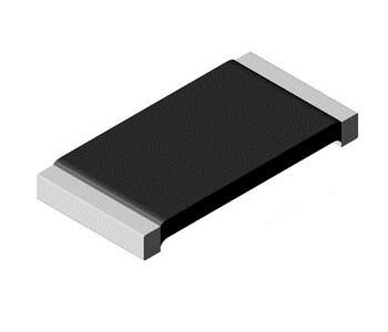
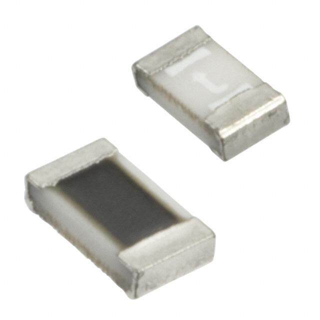
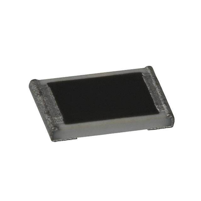
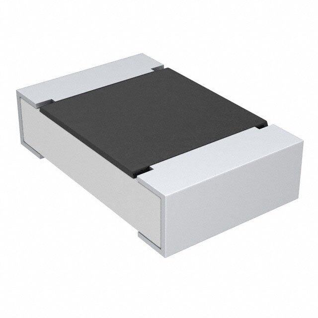
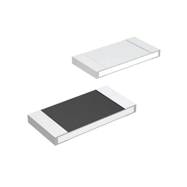
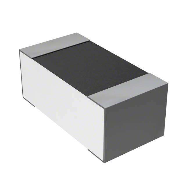
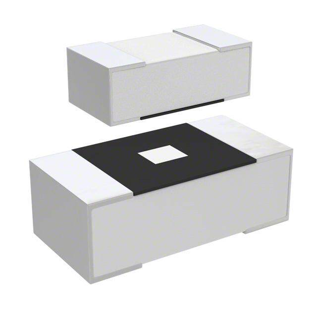
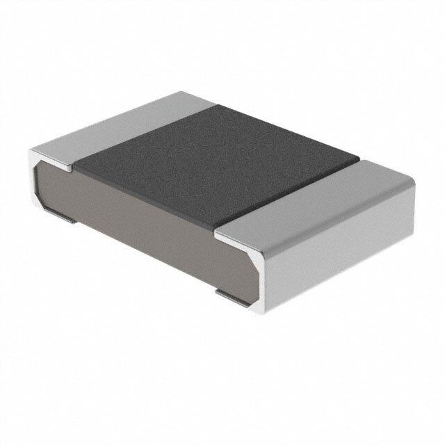
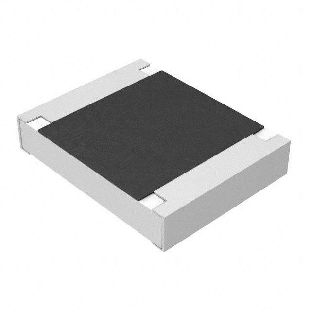
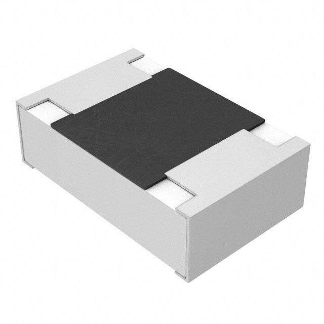
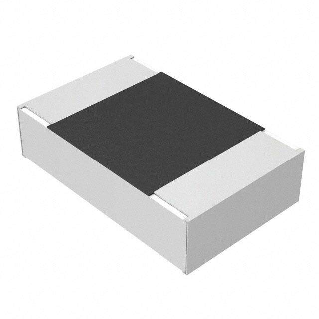
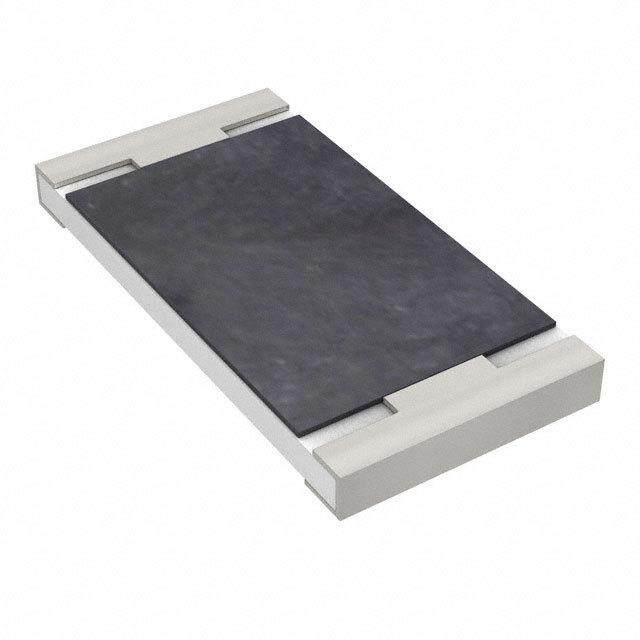
ICGOO电子元器件商城为您提供WSL25123L000FEA由Vishay设计生产,在icgoo商城现货销售,并且可以通过原厂、代理商等渠道进行代购。 WSL25123L000FEA价格参考。VishayWSL25123L000FEA封装/规格:芯片电阻 - 表面安装, 3 mOhms ±1% 1W 金属元素 芯片电阻 2512(6432 公制) 汽车级 AEC-Q200,电流检测,防潮,防脉冲 金属元素。您可以下载WSL25123L000FEA参考资料、Datasheet数据手册功能说明书,资料中有WSL25123L000FEA 详细功能的应用电路图电压和使用方法及教程。
Vishay Dale的WSL25123L000FEA是一款表面安装的芯片电阻,广泛应用于高要求的电子设备中。该型号属于WSL系列,采用金属合金电阻体,具有出色的功率处理能力和稳定性,适用于需要高精度和高可靠性的电路设计。

 应用场景:

1. 电源管理:
   - WSL25123L000FEA常用于电源管理系统中,如开关电源(SMPS)、线性稳压器等。它能够承受较高的功率耗散,并且在高温环境下保持稳定性能,确保电源系统的高效运行。

2. 工业自动化:
   - 在工业控制系统中,这款电阻可以用于电流检测、电压分压等关键环节。其高精度和低温度系数特性使其能够在恶劣的工业环境中提供可靠的信号处理和控制功能。

3. 通信设备:
   - 通信基站、路由器等设备对电阻的要求较高,尤其是在射频(RF)电路中。WSL25123L000FEA的高频特性使其适合用于滤波器、匹配网络等电路,确保信号传输的稳定性和准确性。

4. 汽车电子:
   - 汽车电子系统对元件的可靠性和耐久性要求极高,特别是在发动机控制单元(ECU)、防抱死制动系统(ABS)等关键部位。该电阻的高功率密度和抗振能力使其成为汽车电子的理想选择。

5. 消费电子产品:
   - 在智能手机、平板电脑等消费电子产品中,WSL25123L000FEA可用于电池管理、充电电路等部分。其紧凑的尺寸和优异的电气性能有助于提高产品的整体性能和可靠性。

6. 医疗设备:
   - 医疗设备如心电图机、超声波仪器等对元件的精度和稳定性有严格要求。该电阻的高精度和低噪声特性使其适合用于这些设备中的信号调理和测量电路。

总之,Vishay Dale的WSL25123L000FEA凭借其卓越的电气性能和可靠性,广泛应用于各种高要求的电子设备中,特别适合需要高功率、高精度和高稳定性的应用场景。
| 参数 | 数值 |
| 产品目录 | |
| 描述 | RES .003 OHM 1W 1% 2512 SMD电流传感电阻器 - SMD 1watt .003ohms 1% |
| 产品分类 | |
| 品牌 | Vishay DaleVishay / Dale |
| 产品手册 | http://www.vishay.com/doc?30100 |
| 产品图片 |
|
| rohs | 符合RoHS无铅 / 符合限制有害物质指令(RoHS)规范要求 |
| 产品系列 | 电流传感电阻器,电流传感电阻器 - SMD,Vishay / Dale WSL25123L000FEAWSL |
| 数据手册 | |
| 产品型号 | WSL25123L000FEAWSL25123L000FEA |
| 产品 | Metal Element Current Sensing Resistors |
| 产品目录绘图 |
|
| 产品目录页面 | |
| 产品种类 | 电流传感电阻器 - SMD |
| 供应商器件封装 | 2512 |
| 其它名称 | WSLG-.003TR |
| 功率(W) | 1W |
| 功率额定值 | 1 W |
| 包装 | 带卷 (TR) |
| 单位重量 | 63.600 mg |
| 商标 | Vishay / Dale |
| 商标名 | Power Metal Strip |
| 外壳代码-in | 2512 |
| 外壳代码-mm | 6432 |
| 外壳宽度 | 3.2 mm |
| 外壳长度 | 6.3 mm |
| 外壳高度 | 0.635 mm |
| 大小/尺寸 | 0.250" 长 x 0.125" 宽(6.35mm x 3.18mm) |
| 容差 | ±1%1 % |
| 封装 | Reel |
| 封装/外壳 | 2512(6432 公制) |
| 封装/箱体 | 2512 (6432 metric) |
| 工作温度范围 | - 65 C to + 170 C |
| 工厂包装数量 | 2000 |
| 成分 | 金属元素 |
| 标准包装 | 2,000 |
| 温度系数 | ±150ppm/°C150 PPM / C |
| 特性 | 电流检测 |
| 电阻 | 0.003 Ohms |
| 电阻(Ω) | 0.003 |
| 端子数 | 2 |
| 端接类型 | SMD/SMT |
| 类型 | Power Metal Strip Resistor |
| 系列 | WSL |
| 高度 | 0.035"(0.89mm) |


- 商务部:美国ITC正式对集成电路等产品启动337调查
- 曝三星4nm工艺存在良率问题 高通将骁龙8 Gen1或转产台积电
- 太阳诱电将投资9.5亿元在常州建新厂生产MLCC 预计2023年完工
- 英特尔发布欧洲新工厂建设计划 深化IDM 2.0 战略
- 台积电先进制程称霸业界 有大客户加持明年业绩稳了
- 达到5530亿美元!SIA预计今年全球半导体销售额将创下新高
- 英特尔拟将自动驾驶子公司Mobileye上市 估值或超500亿美元
- 三星加码芯片和SET,合并消费电子和移动部门,撤换高东真等 CEO
- 三星电子宣布重大人事变动 还合并消费电子和移动部门
- 海关总署:前11个月进口集成电路产品价值2.52万亿元 增长14.8%


PDF Datasheet 数据手册内容提取
For Higher Power Upgrade to WSLP WSL www.vishay.com Vishay Dale Power Metal Strip® Resistors, Low Value (Down to 0.0005 ), Surface-Mount FEATURES • All welded construction of the Power Metal Strip® resistors are ideal for all types of current sensing, voltage division and puls e applications Available • Proprietary processing technique produces extremely low resistance values (down to 0.0005 ) • Sulfur resistance by construction that is Available unaffected by high sulfur environments • Very low inductance 0.5 nH to 5 nH Available • Low thermal EMF (< 3 μV/°C) LINKS TO ADDITIONAL RESOURCES • AEC-Q200 qualified (1) Available 3DDD 333D • Material categorization: for definitions of complianc e 3D Models Design Tools Videos Upgrade please see www.vishay.com/doc?99912 Performance Notes * This datasheet provides information about parts that are RoHS-compliant and / or parts that are non-RoHS-compliant. For example, part s with lead (Pb) terminations are not RoHS-compliant. Please see the information / tables in this datasheet for details • Follow link to Overview of Automotive Grade Products for more details: www.vishay.com/doc?49924 (1)Flame retardance test may not be applicable to some resistor technologies STANDARD ELECTRICAL SPECIFICATIONS GLOBAL SIZE POWER RATING P70 °C RESISTANCE VALUE RANGE (2) WEIGHT (typical) MODEL W TOL. ± 0.5 % TOL. ± 1.0 % g/1000 pieces WSL0603 0603 0.1 0.01 to 0.1 0.01 to 0.1 1.9 WSL0805 0805 0.125 0.005 to 0.2 0.005 to 0.2 4.8 WSL1206 1206 0.25 0.005 to 0.2 0.0005 to 0.2 16.2 WSL2010 2010 0.5 0.004 to 0.5 0.001 to 0.5 38.9 WSL2512 2512 1.0 (1) 0.003 to 0.5 0.0005 to 0.5 63.6 WSL2816 2816 2.0 0.003 to 0.1 0.002 to 0.1 118 Notes • Part marking: value; tolerance: due to resistor size limitations some resistors will be marked with only the resistance value (1) For values above 0.1 derate linearly to 80 % rated power at 0.5 (2) WSL1206 0.0005 to 0.00099 is only available with 2 % tolerance (G tolerance code) GLOBAL PART NUMBER INFORMATION Global Part Numbering Example: WSL25124L000FEA (visit www.vishay.net Vishay Dale parts numbering manual for all options) W S L 2 5 1 2 4 L 0 0 0 F E A GLOBAL RESISTANCE TOLERANCE PACKAGING CODE (2) SPECIAL (3) MODEL VALUE (1) CODE (2 digits) (up to 2 digits) (7 digits) (5 digits) (1 digit) WSL0603 L = m* D = ± 0.5 % EA = lead (Pb)-free, tape / reel (dash number) WSL0805 R = decimal F = ± 1.0 % EH = lead (Pb)-free, tape / reel (WSL2816) from 1 to 99 as WSL1206 5L000 = 0.005 J = ± 5.0 % applicable TA = tin / lead, tape / reel (R86) WSL2010 R0100 = 0.01 TG = tin / lead, tape / reel (RT1, for WSL0603 and WSL0805) WSL2512 TH = tin / lead, tape / reel (RJ9, WSL2816) WSL2816 * Use “L” for resistance SB = tin / lead, tape / reel for DLA drawings values < 0.01 Notes (1) WSL marking (www.vishay.com/doc?30327); WSL decade values (www.vishay.com/doc?30117) (2) Packaging code: EB (lead (Pb)-free) and TB (tin / lead) are non-standard packaging codes designating 1000 piece reels. These non-standar d packaging codes are identical to our standard EA (lead (Pb)-free) and TA (tin / lead), except that they have a package quantity of 1000 pieces (3) Follow link for customization capabilities: www.vishay.com/doc?48163 Revision: 27-Apr-2020 1 Document Number: 30100 For technical questions, contact: ww2bresistors@vishay.com THIS DOCUMENT IS SUBJECT TO CHANGE WITHOUT NOTICE. THE PRODUCTS DESCRIBED HEREIN AND THIS DOCUMENT ARE SUBJECT TO SPECIFIC DISCLAIMERS, SET FORTH AT www.vishay.com/doc?91000
For Higher Power Upgrade to WSLP WSL www.vishay.com Vishay Dale TECHNICAL SPECIFICATIONS WSL RESISTOR CHARACTERISTICS PARAMETER UNIT WSL0603 (1) WSL0805 WSL1206 WSL2010 WSL2512 WSL2816 ± 75 for 50 m to 100 m ± 75 for 7 m to 500 m Component temperature coefficient ± 110 for 10 m to 49 m ± 110 for 5 m to 6.9 m (including terminal) (2) ppm/°C - ± 150 for 3 m to 4.9 m TCR measured from -55 °C to +155 °C - ± 275 for 1 m to 2.9 m - ± 400 for 0.5 m to 0.99 m Element TCR (3) ppm/°C < 20 Operating temperature range °C -65 to +170 Maximum working voltage (4) V (P x R)1/2 Notes (1) Consult factory for detailed TCR performance across temperature range associated with PCN-DR-00003-2020 for WSL0603. TCR performance is improved for +25 °C to +155 °C (2) Component TCR - total TCR that includes the TCR effects of the resistor element and the copper terminal (3) Element TCR - only applies to the alloy used for the resistor element; refer to item 1 in the construction illustration on the following page (4) Maximum working voltage - the WSL is not voltage sensitive, but is limited by power / energy dissipation and is also not ESD sensitive DIMENSIONS in inches (millimeters) H l b W T a L Typical sensing traces Notes • 3D models available: www.vishay.com/doc?30306 • Surface mount solder profile recommendations: www.vishay.com/doc?31052 RESISTANCE DIMENSIONS SOLDER PAD DIMENSIONS MODEL RANGE () L W H T a b l 0.060 ± 0.010 0.030 ± 0.010 0.016 ± 0.005 0.015 ± 0.010 0.040 0.040 0.020 WSL0603 (1) 0.01 to 0.1 (1.52 ± 0.254) (0.76 ± 0.254) (0.406 ± 0.127) (0.381 ± 0.254) (1.01) (1.01) (0.50) 0.080 ± 0.010 0.050 ± 0.010 0.013 ± 0.005 0.015 ± 0.010 0.040 0.050 0.020 WSL0805 0.005 to 0.2 (2.03 ± 0.254) (1.27 ± 0.254) (0.330 ± 0.127) (0.381 ± 0.254) (1.02) (1.27) (0.50) 0.089 0.076 0.023 0.0005 to 0.00099 0.041 ± 0.010 (2.26) (1.93) (0.58) (1.04 ± 0.254) 0.086 0.076 0.029 0.001 to 0.0019 0.126 ± 0.010 0.063 ± 0.010 0.025 ± 0.010 (2.18) (1.93) (0.74) WSL1206 (3.20 ± 0.254) (1.60 ± 0.254) (0.635 ± 0.254) 0.025 ± 0.010 0.070 0.076 0.061 0.002 to 0.0059 (0.635 ± 0.254) (1.78) (1.93) (1.55) 0.020 ± 0.010 0.065 0.076 0.071 0.006 to 0.20 (0.508 ± 0.254) (1.65) (1.93) (1.80) 0.058 ± 0.010 0.093 0.120 0.055 0.001 to 0.0069 0.200 ± 0.010 0.100 ± 0.010 0.025 ± 0.010 (1.47 ± 0.254) (2.36) (3.05) (1.40) WSL2010 (5.08 ± 0.254) (2.54 ± 0.254) (0.635 ± 0.254) 0.020 ± 0.010 0.055 0.120 0.130 0.007 to 0.5 (0.508 ± 0.254) (1.40) (3.05) (3.30) 0.107 ± 0.010 0.0005 to 0.00099 (2.72 ± 0.254) 0.120 0.050 0.087 ± 0.010 (3.05) (1.27) 0.001 to 0.0049 0.250 ± 0.010 0.125 ± 0.010 0.025 ± 0.010 (2.21 ± 0.254) 0.145 WSL2512 (6.35 ± 0.254) (3.18 ± 0.254) (0.635 ± 0.254) 0.047 ± 0.010 0.083 (3.68) 0.125 0.005 to 0.0069 (1.19 ± 0.254) (2.11) (3.18) 0.030 ± 0.010 0.065 0.160 0.007 to 0.5 (0.762 ± 0.254) (1.65) (4.06) 0.098 ± 0.010 0.135 0.060 0.002 to 0.00399 0.280 ± 0.010 0.165 ± 0.010 0.025 ± 0.010 (2.49 ± 0.254) (3.43) 0.185 (1.52) WSL2816 (7.1 ± 0.254) (4.2 ± 0.254) (0.635 ± 0.254) 0.062 ± 0.010 0.096 (4.7) 0.125 0.004 to 0.1 (1.57 ± 0.254) (2.45) (3.20) Note (1) PCN-DR-00003-2020 changed terminal height for WSL0603 from 0.013" ± 0.005" for clad construction to 0.016" ± 0.005" for welde d construction Revision: 27-Apr-2020 2 Document Number: 30100 For technical questions, contact: ww2bresistors@vishay.com THIS DOCUMENT IS SUBJECT TO CHANGE WITHOUT NOTICE. THE PRODUCTS DESCRIBED HEREIN AND THIS DOCUMENT ARE SUBJECT TO SPECIFIC DISCLAIMERS, SET FORTH AT www.vishay.com/doc?91000
For Higher Power Upgrade to WSLP WSL www.vishay.com Vishay Dale DERATING PULSE CAPABILITY % 120 wer in 100 click to get started OO N LLLLL YY o EE SS d P 80 PP O S e RR Rat 60 E P U V TI AAA R 40 T S U LL LL 20 II 0 - 65 - 50 - 25 0 25 50 75 100 125 150 170 Ambient Temperature in °C 70 www.vishay.com/resistors/power-metal-strip-calculator WELDED CONSTRUCTION CLAD CONSTRUCTION 2816, 2512, 2010, 1206, 0603 0805 1 Resistive element: solid metal nickel-chrome 1 Resistive element: Ni-Cr or manganese-copper 2 Terminal: solid copper, alloy resistive element with 100 % Sn (100 μ" min.) with low TCR (< 20 ppm/°C) 100 % Ni (20 μ" min.) under 2 Plated terminal: solid copper, 4 layer finish 100 % Sn (100 μ" min.) with 3 Terminal to element weld 4 100 % Ni (20 μ" min.) under 1 layer finish 1 4 High temperature encapsulant: 2 3 3 Terminal / element weld 2 3 “siliconized polyester” coating material 4 Silicone coating with ink print PERFORMANCE TEST CONDITIONS OF TEST TEST LIMITS Thermal shock -55 °C to +150 °C, 1000 cycles, 15 min at each extreme ± 0.5 % + 0.0005 Refer to link for short time overload performance and pulse capability; Short time overload ± 0.5 % + 0.0005 www.vishay.com/resistors/power-metal-strip-calculator/ Low temperature operation -65 °C for 24 h ± 0.5 % + 0.0005 High temperature exposure 1000 h at + 170 °C ± 1.0 % + 0.0005 Bias humidity +85 °C, 85 % RH, 10 % bias, 1000 h ± 0.5 % + 0.0005 Mechanical shock 100 g’s for 6 ms, 5 pulses ± 0.5 % + 0.0005 Vibration Frequency varied 10 Hz to 2000 Hz in 1 min, 3 directions, 12 h ± 0.5 % + 0.0005 Load life 1000 h at rated power, + 70 °C, 1.5 h “ON”, 0.5 h “OFF” ± 1.0 % + 0.0005 Resistance to solder heat +260 °C solder, 10 s to 12 s dwell, 25 mm/s emergence ± 0.5 % + 0.0005 Moisture resistance MIL-STD-202, method 106, 0 % power, 7a and 7b not required ± 0.5 % + 0.0005 PACKAGING (1) REEL MODEL TAPE WIDTH DIAMETER PIECES/REEL CODE WSL0603 8 mm / punched paper 178 mm / 7" 5000 EA WSL0805 8 mm / punched paper 178 mm / 7" 5000 EA WSL1206 8 mm / embossed plastic 178 mm / 7" 4000 EA WSL2010 12 mm / embossed plastic 178 mm / 7" 4000 EA WSL2512 12 mm / embossed plastic 178 mm / 7" 2000 EA WSL2816 12 mm / embossed plastic 178 mm / 7" 2000 EH Notes • Embossed carrier tape per EIA-481 (1) Additional packaging details at www.vishay.com/doc?20051 Revision: 27-Apr-2020 3 Document Number: 30100 For technical questions, contact: ww2bresistors@vishay.com THIS DOCUMENT IS SUBJECT TO CHANGE WITHOUT NOTICE. THE PRODUCTS DESCRIBED HEREIN AND THIS DOCUMENT ARE SUBJECT TO SPECIFIC DISCLAIMERS, SET FORTH AT www.vishay.com/doc?91000
Legal Disclaimer Notice www.vishay.com Vishay Disclaimer ALL PRODUCT, PRODUCT SPECIFICATIONS AND DATA ARE SUBJECT TO CHANGE WITHOUT NOTICE TO IMPROV E RELIABILITY, FUNCTION OR DESIGN OR OTHERWISE. Vishay Intertechnology, Inc., its affiliates, agents, and employees, and all persons acting on its or their behalf (collectively, “Vishay”), disclaim any and all liability for any errors, inaccuracies or incompleteness contained in any datasheet or in any other disclosure relating to any product. Vishay makes no warranty, representation or guarantee regarding the suitability of the products for any particular purpose o r the continuing production of any product. To the maximum extent permitted by applicable law, Vishay disclaims (i) any and all liability arising out of the application or use of any product, (ii) any and all liability, including without limitation special, consequential or incidental damages, and (iii) any and all implied warranties, including warranties of fitness for particular purpose, non-infringement and merchantability. Statements regarding the suitability of products for certain types of applications are based on Vishay’s knowledge of typical requirements that are often placed on Vishay products in generic applications. Such statements are not binding statements about the suitability of products for a particular application. It is the customer’s responsibility to validate that a particular product with the properties described in the product specification is suitable for use in a particular application. Parameters provided in datasheets and / or specifications may vary in different applications and performance may vary over time. All operating parameters, including typical parameters, must be validated for each customer application by the customer’s technical experts. Product specifications do not expand or otherwise modify Vishay’s terms and conditions of purchase, including but not limited to the warranty expressed therein. Except as expressly indicated in writing, Vishay products are not designed for use in medical, life-saving, or life-sustainin g applications or for any other application in which the failure of the Vishay product could result in personal injury or death. Customers using or selling Vishay products not expressly indicated for use in such applications do so at their own risk . Please contact authorized Vishay personnel to obtain written terms and conditions regarding products designed for such applications. No license, express or implied, by estoppel or otherwise, to any intellectual property rights is granted by this documen t or by any conduct of Vishay. Product names and markings noted herein may be trademarks of their respective owners. © 2019 VISHAY INTERTECHNOLOGY, INC. ALL RIGHTS RESERVED Revision: 01-Jan-2019 1 Document Number: 91000