ICGOO在线商城 > VX-012-1A3

 Datasheet下载
- 型号: VX-012-1A3
- 制造商: Omron Electronics LLC
- 库位|库存: xxxx|xxxx
- 要求:
| 数量阶梯 | 香港交货 | 国内含税 |
| +xxxx | $xxxx | ¥xxxx |
查看当月历史价格
查看今年历史价格
VX-012-1A3产品简介:
ICGOO电子元器件商城为您提供VX-012-1A3由Omron Electronics LLC设计生产,在icgoo商城现货销售,并且可以通过原厂、代理商等渠道进行代购。 提供VX-012-1A3价格参考以及Omron Electronics LLCVX-012-1A3封装/规格参数等产品信息。 你可以下载VX-012-1A3参考资料、Datasheet数据手册功能说明书, 资料中有VX-012-1A3详细功能的应用电路图电压和使用方法及教程。
| 参数 | 数值 |
| 产品目录 | |
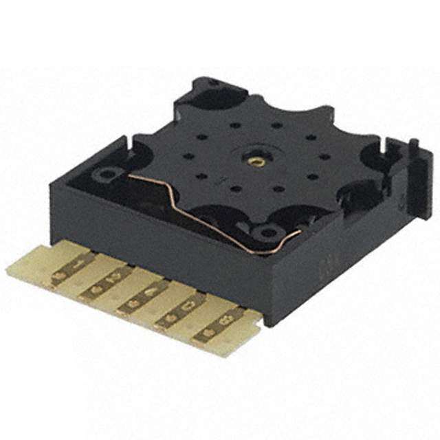
| 描述 | SW BASIC SPDT .1A .187QC 125V基本/快动开关 .1A Switch Basic SPDT .187QC |
| 产品分类 | |
| IP等级 | IP 40 |
| 品牌 | Omron Electronics |
| 产品手册 | |
| 产品图片 |
|
| rohs | 符合RoHS无铅 / 符合限制有害物质指令(RoHS)规范要求 |
| 产品系列 | 基本/快动开关,Omron Electronics VX-012-1A3VX |
| mouser_ship_limit | 该产品可能需要其他文件才能进口到中国。 |
| 数据手册 | |
| 产品型号 | VX-012-1A3 |
| 产品培训模块 | http://www.digikey.cn/PTM/IndividualPTM.page?site=cn&lang=zhs&ptm=19281 |
| 产品目录绘图 |
|
| 产品目录页面 | |
| 产品种类 | 基本/快动开关 |
| 侵入防护 | IP40 |
| 其它名称 | SW987 |
| 其它有关文件 | |
| 包装 | 散装 |
| 商标 | Omron Electronics |
| 安装 | Panel |
| 安装类型 | 底座安装 |
| 工作位置 | 0.600" (15.2mm) |
| 工作力 | 0.49 N |
| 工作温度 | -25°C ~ 80°C |
| 工厂包装数量 | 100 |
| 差动行程 | 0.030" (0.76mm) |
| 开关功能 | ON - (OFF), OFF - (ON) |
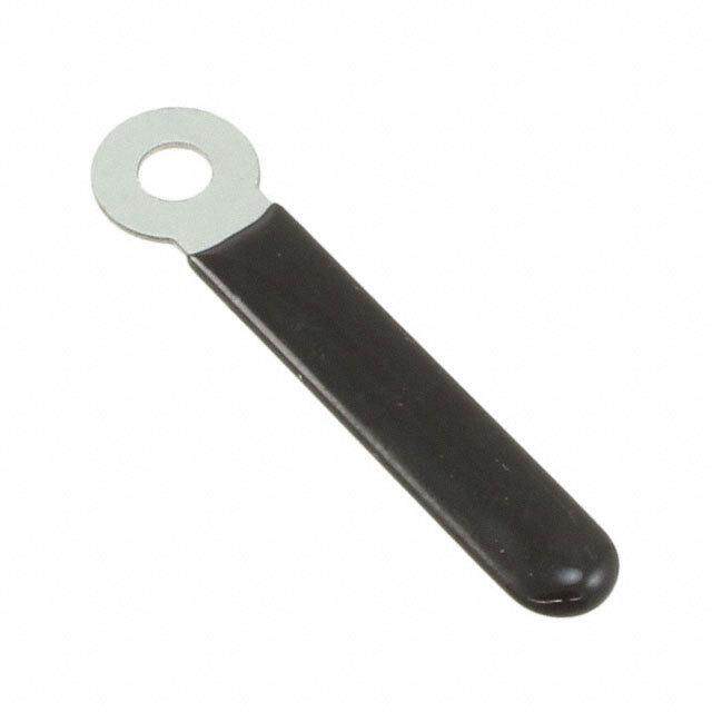
| 执行器 | Lever |
| 操作力,扭矩 | 30gf |
| 机械寿命 | 10,000,000 次循环 |
| 标准包装 | 100 |
| 特性 | - |
| 电压额定值AC | 125 V |
| 电压额定值DC | 30 V |
| 电气寿命 | 1,000,000 次循环 |
| 电流额定值 | 100 mA |
| 电路 | SPDT |
| 相关产品 | /product-detail/zh/360010-1/A24758-ND/287849/product-detail/zh/0006023031/WM2553-ND/114996 |
| 端子类型 | 焊接,快速连接 - 0.187"(4.7mm) |
| 端接类型 | Solder Lug |
| 类型 | Miniature |
| 系列 | VX |
| 致动器类型 | 按片,直形 |
| 触点形式 | SPDT |
| 超行程 | 0.062" (1.6mm) |
| 释放力 | - |
| 零件号别名 | 1536204 383551 |
| 预行程 | 0.157" (4.0mm) |
| 额定电压-AC | 125V |
| 额定电压-DC | 30V |
| 额定电流 | 100mA(AC/DC) |


.jpg)


PDF Datasheet 数据手册内容提取
VX Miniature Basic Switch Miniature Basic Switch with Low Operating Force and High Contact Reliability ●Wide variation extends from micro load to 5A V X switching current, with shapes identical to those of the V-series Miniature Basic Switch. ●Unique internal mechanism ensures the high contact reliability even in micro load operations. Applicable for detection of lightweight objects. RoHS Compliant Model Number Legend @ @ @ @ @ @ VX- 1 2 3 - 4 5 6 1. Ratings 4. Contact form 5 : 250 VAC 5 A 1 : SPDT 01 : 30 VDC 0.1 A 2 : SPST-NC 3 : SPST-NO 2. Actuator None : Pin plunger 5. Terminals 1 : Short hinge lever A : Solder terminals 2 : Hinge lever C2 : Quick Connect Terminal (#187) 3 : Long hinge lever 6. Maximum Operating Force (OF) 4 : Simulated roller lever 2 : 0.25N {25 gf} (for pin plungers only) 5 : Short hinge roller lever 3 : 0.49N {50 gf} 6 : Hinge roller lever 3. Lever mounting position Note.These values are for the pin plunger models. None : Lever set distant from plunger (Standard Position) 8.1 K : Lever set close to plunger (Position K) 14.1 1
VX Miniature Basic Switch List of Models Ratings 5 A 0.1 A Contact Lever mounting position Standard Position Position K Standard Position Position K Actuator Terminals Form Maximum Operating Force (OF) SPDT VX-5-1A2 - VX-01-1A2 - SPST-NC 0.25 N {25 gf} VX-5-2A2 - VX-01-2A2 - SPST-NO VX-5-3A2 - VX-01-3A2 - Solder terminals SPDT VX-5-1A3 - VX-01-1A3 - SPST-NC 0.49 N {50 gf} VX-5-2A3 - VX-01-2A3 - Pin plunger SPST-NO VX-5-3A3 - VX-01-3A3 - SPDT VX-5-1C22 - VX-01-1C22 - V SPST-NC 0.25 N {25 gf} VX-5-2C22 - VX-01-2C22 - X Quick Connect SPST-NO VX-5-3C22 - VX-01-3C22 - Terminal (#187) SPDT VX-5-1C23 - VX-01-1C23 - SPST-NC 0.49 N {50 gf} VX-5-2C23 - VX-01-2C23 - SPST-NO VX-5-3C23 - VX-01-3C23 - SPDT VX-51-1A3 - VX-011-1A3 - Solder terminals SPST-NC VX-51-2A3 - VX-011-2A3 - Short hinge lever SPST-NO VX-51-3A3 - VX-011-3A3 - 0.49 N {50 gf} SPDT VX-51-1C23 - VX-011-1C23 - Quick Connect SPST-NC VX-51-2C23 - VX-011-2C23 - Terminal (#187) SPST-NO VX-51-3C23 - VX-011-3C23 - SPDT VX-52-1A3 - VX-012-1A3 - Hinge lever Solder terminals SPST-NC VX-52-2A3 - VX-012-2A3 - SPST-NO VX-52-3A3 - VX-012-3A3 - 0.29 N {30 gf} SPDT VX-52-1C23 - VX-012-1C23 - Quick Connect SPST-NC VX-52-2C23 - VX-012-2C23 - Terminal (#187) SPST-NO VX-52-3C23 - VX-012-3C23 - SPDT VX-53-1A3 VX-53K-1A3 VX-013-1A3 VX-013K-1A3 Long hinge lever Solder terminals SPST-NC VX-53-2A3 VX-53K-2A3 VX-013-2A3 VX-013K-2A3 SPST-NO VX-53-3A3 VX-53K-3A3 VX-013-3A3 VX-013K-3A3 0.20 N {20 gf} SPDT VX-53-1C23 VX-53K-1C23 VX-013-1C23 VX-013K-1C23 Quick Connect SPST-NC VX-53-2C23 VX-53K-2C23 VX-013-2C23 VX-013K-2C23 Terminal (#187) SPST-NO VX-53-3C23 VX-53K-3C23 VX-013-3C23 VX-013K-3C23 SPDT VX-54-1A3 VX-54K-1A3 VX-014-1A3 VX-014K-1A3 Simulated roller lever Solder terminals SPST-NC VX-54-2A3 VX-54K-2A3 VX-014-2A3 VX-014K-2A3 SPST-NO VX-54-3A3 VX-54K-3A3 VX-014-3A3 VX-014K-3A3 0.29 N {30 gf} SPDT VX-54-1C23 VX-54K-1C23 VX-014-1C23 VX-014K-1C23 Quick Connect SPST-NC VX-54-2C23 VX-54K-2C23 VX-014-2C23 VX-014K-2C23 Terminal (#187) SPST-NO VX-54-3C23 VX-54K-3C23 VX-014-3C23 VX-014K-3C23 SPDT VX-55-1A3 - VX-015-1A3 - Short hinge roller Solder terminals SPST-NC VX-55-2A3 - VX-015-2A3 - lever SPST-NO VX-55-3A3 - VX-015-3A3 - 0.59 N {60 gf} SPDT VX-55-1C23 - VX-015-1C23 - Quick Connect SPST-NC VX-55-2C23 - VX-015-2C23 - Terminal (#187) SPST-NO VX-55-3C23 - VX-015-3C23 - SPDT VX-56-1A3 VX-56K-1A3 VX-016-1A3 VX-016K-1A3 Hinge roller lever Solder terminals SPST-NC VX-56-2A3 VX-56K-2A3 VX-016-2A3 VX-016K-2A3 SPST-NO VX-56-3A3 VX-56K-3A3 VX-016-3A3 VX-016K-3A3 0.29 N {30 gf} SPDT VX-56-1C23 VX-56K-1C23 VX-016-1C23 VX-016K-1C23 Quick Connect SPST-NC VX-56-2C23 VX-56K-2C23 VX-016-2C23 VX-016K-2C23 Terminal (#187) SPST-NO VX-56-3C23 VX-56K-3C23 VX-016-3C23 VX-016K-3C23 Contact Form ●SPDT ●SPST-NC ●SPST-NO NC NC NO NO COM COM COM Separator (Sold Separately), Actuator (Sold Separately), Terminal Connector (Sold Separately) Refer to "Basic Switch Common Accessories" 2
VX Miniature Basic Switch Contact Specifications Characteristics Item Model VX-5 models VX-01 models Item Model VX-5 models VX-01 models Specification Rivet Crossbar Permissible operating speed 0.1 mm to 1 m/s (for pin plunger models) Contact Material Silver alloy Gold alloy Permissible Mechanical 600 operations/min (for pin plunger models) operating Gap (standard value) 0.5 mm frequency Electrical 60 operations/min Inrush NC 15 A max. - Insulation resistance 100 MΩ min. (at 500 VDC with insulation tester) current NO 15 A max. - Contact resistance (initial value) 30 mΩ max. 50 mΩ max. Minimum applicable load 5 VDC 160 mA 5 VDC 1 mA Between terminals of the (reference value) * 1,000 VAC 50/60 Hz for 1 min same polarity * Please refer to "Using Micro Loads" in "●Precautions" for more Between current-carrying V information on the minimum applicable load. Dielectric metal parts and ground 1,500 VAC 50/60 Hz for 1 min X strength *1 Ratings Between terminals and non-current-carrying 1,500 VAC 50/60 Hz for 1 min metal parts Item Vibration Resistive load Malfunction 10 to 55 Hz, 1.5 mm double amplitude Model Rated voltage resistance *2 VX-5 models 250 VAC 5 A Shock Durability 400 m/s2 {approx. 40G} max. 125 VAC 0.1 A resistance Malfunction *2 100 m/s2 {approx. 10G} max. VX-01 models 30 VDC 0.1 A Mechanical 50,000,000 operations min. 10,000,000 operations min. (60 operations/min) (60 operations/min) Note.The above rating values apply under the following test conditions. Durability *3 (1) Ambient temperature: 20±2°C Electrical 500,000 operations min. 1,000,000 operations min. (2) Ambient humidity: 65±5% (30 operations/min) (30 operations/min) (3) Operating frequency: 30 operations/min Degree of protection IEC IP40 Degree of protection against electric Approved Safety Standards Class I shock Proof tracking index (PTI) 175 UL (UL1054)/CSA (CSA C22.2 No.55) -25 to 105°C (at ambient humidity of Ambient operating temperature Rated voltage Model VX-5 VX-01 60% max.) (with no icing or condensation) 125 VAC 5 A 0.1 A Ambient operating humidity 85% max. (for 5 to 35°C) 250 V 5 A - Weight Approx. 6.2 g (pin plunger models) 30 VDC - 0.1 A Note.The data given above are initial values. *1. The values for dielectric strength shown are for models with a Separator VDE (EN61058-1) (refer to "Micro Switch Common Accessories"). Rated voltage Model VX-5 VX-01 *2. For the pin plunger models, the above values apply for use at the free position and total travel position. For the lever models, they apply at the 250VAC 5 A - total travel position. Close or open circuit of the contact is 1 ms max. 125VAC 5 A 0.1 A *3. For testing conditions, consult your OMRON sales representative. Testing conditions: 5E4 (50,000 operations) T105 (0 to 105°C) Terminals/Appearances Mounting Holes (Unit: mm) (Unit: mm) Solder terminals Quick Connect Terminal (#187) 2-3.1 dia. mounting holes or M3 screw holes (5.5) (5.5) (6.5) (6.5) 10.3±0.1 2.9 2.9 t=0.5 (10) t=0.5 (10) 22.2±0.1 3-Solder terminals 3-Quick Connect Terminal (#187) 6.35 6.35 3.2* 3.2 4.75±0.1 4.75±0.1 2.4 dia. 1.6 dia. 1.6 dia. terminal holes * This indicates the length to the center of 1.6 dia. hole. Note.The above is for the SPDT contact specifications. 3
VX Miniature Basic Switch Dimensions and Operating Characteristics (Unit: mm) The following illustrations and drawings are for solder terminals. Illustrations for Quick Connect Terminal (#187) are omitted. For details, refer to "Terminals/Appearances" on previous page. The @ is replaced with the code for the terminals. See the "List of Models" for available combinations of shapes. ●Pin plunger VX-5-1@2 20.2±0.25 4.22.8 Model VX-5-1@2 VX-5-1@3 VX-5-1@3 PT A 2.8 3.1+-00..1033 dia. holes Operating Characteristics VX-01-1@2 VX-01-1@3 VX-01-1@2 2.8 Operating Force OF Max. 0.25 N {25 gf} 0.49 N {50 gf} VX-01-1@3 OP10.3±0.1 15.9 18.8 Releasing Force RF Min. 0.03 N {3 gf} 0.05 N {5 gf} Pretravel PT Max. 1.2 mm V Overtravel OT Min. 1.0 mm X 3.1+-00..0133 3.4±0.15 dia. Movement Differential MDMax. 0.3 mm 22.2±0.1 2.8 10.3 Operating Position OP 14.7±0.4 mm 3-Solder terminals 27.8 (10) 37.8±0.8 ●Short hinge lever (Standard Position) VX-51-1@3 t=0.5* Model VX-51-1@3 VX-011-1@3 22.1 Operating Characteristics VX-011-1@3 PT A 8.1 3.1+-00..1033 dia. holes 4.32.8 Operating Force OF Max. 0.49 N {50 gf} Releasing Force RF Min. 0.04 N {4 gf} 2.8 (reference value) OP 10.3±0.1 15.9 18.8 Pretravel PT Max. 1.6 mm Overtravel OT Min. 0.8 mm 3.1+-00..0133 3.4±0.15 dia. 10.3 MOpoeveramtienngt PDoifsfietiroenn tial MOPD Max. 15.02.±50 m.5m m m 22.2±0.1 2.8 3-Solder terminals Note.The indicated reference values of RF are for cases 27.8 (10) where the lever weight is not applied to the plunger. 37.8±0.8 * Stainless-steel lever ●Hinge lever (Standard Position) VX-52-1@3 VX-012-1@3 PT A t=03.55*.6±0.8 8.1 3.1+-00..1033 dia. holes 4.32.8 Operating Characteristics Model VVXX--5021-21-@1@33 Operating Force OF Max. 0.29 N {30 gf} 2.8 Releasing Force RF Min. - OP 10.3±0.1 15.9 18.8 Pretravel PT Max. 4.0 mm Overtravel OT Min. 1.6 mm Movement Differential MD Max. 0.8 mm 3.1+-00..0133 3.4±0.15 dia. Operating Position OP 15.2±1.2 mm 10.3 22.2±0.1 2.8 3-Solder terminals 27.8 (10) 37.8±0.8 * Stainless-steel lever ●Long hinge lever (Standard Position) VX-53-1@3 t=0.5* Model VX-53-1@3 VX-013-1@3 A 59.4±0.8 Operating Characteristics VX-013-1@3 PT 8.1 3.1+-00..1033 dia. holes 4.32.8 Operating Force OF Max. 0.20 N {20 gf} Releasing Force RF Min. - 2.8 Pretravel PT Max. 9.0 mm OP 10.3±0.1 15.9 18.8 Overtravel OT Min. 3.2 mm Movement Differential MD Max. 2.0 mm 3.1+-00..0133 3.4±0.15 dia. 10.3 Operating Position OP 15.2±2.6 mm 22.2±0.1 2.8 3-Solder terminals 27.8 (10) 37.8±0.8 * Stainless-steel lever ●Long hinge lever (Position K) t=0.5* VX-53K-1@3 VX-013K-1@3 PT A 65.4±0.8 14.1 3.1+-00..1033 dia. holes 4.32.8 Operating Characteristics Model VVXX--50133KK-1-@1@33 2.8 Operating Force OF Max. 0.12 N {12 gf} OP Releasing Force RF Min. - 10.3±0.1 15.9 18.8 Pretravel PT Max. 15.0 mm Overtravel OT Min. 5.0 mm 3.1+-00..0133 3.4±0.15 dia. Movement Differential MD Max. 4.2 mm 22.2±0.1 2.8 10.3 Operating Position OP 15.2±4.4 mm 3-Solder terminals 27.8 (10) 37.8±0.8 * Stainless-steel lever Note 1.Unless otherwise specified, a tolerance of ±0.4 mm applies to all dimensions. Note 2.The operating characteristics are for operation in the A direction ( ). 4
VX Miniature Basic Switch ●Simulated roller lever (Standard Position) VX-54-1@3 R3.5 VX-014-1@3 PT A t=0.5*32.6±0.8 8.1 4.32.8 Operating Characteristics Model VVXX--5041-41-@1@33 3.1+-00..1033 dia. holes Operating Force OF Max. 0.29 N {30 gf} Releasing Force RF Min. 0.02 N {2 gf} 2.8 OP Pretravel PT Max. 4.0 mm 10.3±0.1 15.9 18.8 Overtravel OT Min. 1.6 mm Movement Differential MD Max. 0.8 mm 3.1+-00..0133 232.4.2±0±.01.51 dia. 2.8 10.3 Operating Position OP 18.7±1.2 mm V 27.8 3-Solder terminals X (10) 37.8±0.8 * Stainless-steel lever ●Simulated roller lever (Position K) VX-54K-1@3 VX-014K-1@3 PT A Rt=30.5.53*8.6±0.8 14.1 4.32.8 Operating Characteristics Model VVXX--05144KK-1-1@@33 3.1+-00..1033 dia. holes Operating Force OF Max. 0.18 N {18 gf} Releasing Force RF Min. (0.01 N {1 gf}) 2.8 OP Pretravel PT Max. 7.2 mm 10.3±0.1 15.9 18.8 Overtravel OT Min. 2.5 mm Movement Differential MD Max. 2.0 mm 3.1+-00..0133 3.4±0.15 dia. 10.3 Operating Position OP 18.7±2.2 mm 22.2±0.1 2.8 3-Solder terminals 27.8 (10) 37.8±0.8 * Stainless-steel lever ●Short hinge roller lever (Standard Position) VX-55-1@3 t=0.5 *1 VX-015-1@3 PT A 20.18.1 4.8x4.85 .*12 dia. Operating Characteristics Model VVXX--5051-51-@1@33 2.8 3.1+-00..1033 dia. holes ORepleeraastiinngg FFoorrccee ORFF MMainx. . 0.05.094 N N {{640 g gf}f } OP (reference value) 10.3±0.1 15.9 18.8 Pretravel PT Max. 1.6 mm Overtravel OT Min. 0.8 mm 3.1+-00..0133 3.4±0.15 dia. 10.3 MOpoevreamtienngt PDoifsfietiroenn tial MOPD Max. 20.07.±50 m.6m m m 22.2±0.1 2.8 3-Solder terminals Note.The indicated reference values of RF are for cases where the 27.8 (10) lever weight is not applied to the plunger. 37.8±0.8 *1. Stainless-steel lever *2. Polyacetal resin roller ●Hinge roller lever (Standard Position) VX-56-1@3 t=0.5 *1 VX-016-1@3 PT A 34±0.8 8.1 4.8x4.85 .*12 dia. Operating Characteristics Model VVXX--5061-61-1@@3 3 2.8 3.1+-00..1033 dia. holes ORepleeraastiinngg FFoorrccee ORFF MMainx. . 0.29 N- {30 gf} OP Pretravel PT Max. 4.0 mm 10.3±0.1 15.9 18.8 Overtravel OT Min. 1.6 mm Movement Differential MD Max. 0.8 mm 3.1+-00..0133 3.4±0.15 dia. 10.3 Operating Position OP 20.7±1.2 mm 22.2±0.1 2.8 3-Solder terminals 27.8 (10) 37.8±0.8 *1. Stainless-steel lever *2. Polyacetal resin roller ●Hinge roller lever (Position K) VX-56K-1@3 t=0.5 *1 4.8x4.8 *2 dia. VX-016K-1@3 PT A 40±0.8 14.1 5.1 Operating Characteristics Model VVXX--05166KK-1-@1@33 3.1+-00..1033 dia. holes Operating Force OF Max. 0.18 N {18 gf} Releasing Force RF Min. (0.01 N {1 gf}) OP 2.8 Pretravel PT Max. 7.2 mm 10.3±0.1 15.9 18.8 Overtravel OT Min. 2.5 mm Movement Differential MD Max. 2.0 mm 3.1+-00..0133 3.4±0.15 dia. Operating Position OP 20.7±2.2 mm 10.3 22.2±0.1 2.8 3-Solder terminals 27.8 (10) 37.8±0.8 *1. Stainless-steel lever *2. Polyacetal resin roller Note 1.Unless otherwise specified, a tolerance of ±0.4 mm applies to all dimensions. Note 2.The operating characteristics are for operation in the A direction ( ). 5
VX Miniature Basic Switch Precautions ★Please refer to "Common Precautions" for correct use. Cautions Correct Use ●Handling ●Mounting Do not apply excessive shock. Doing so may cause damage to Use M3 mounting screw with plane washers or spring washers to the Switch's internal components because it is designed for a securely mount the Switch. Tighten the screws to a torque of small load. 0.39 to 0.59 N·m {4 to 6 kgf·cm}. V ●Soldering ●Mounting Direction X (cid:129)Terminal connections For a Switch with an actuator, mount the Switch in a direction Complete the soldering at the iron tip temperature between where the actuator weight will not be applied to the Switch. 250 to 350°C (60W) within 5 seconds, and do not apply any Since the Switch is designed for a small load, its resetting force external force for 1 minute after soldering. is small. Therefore, resetting failure may occur if unnecessary Apply minimum amount of flux required. It may result in load is applied to the Switch. contact failure once the flux penetrates into the internal part of ●Using Micro Loads the Switch. (cid:129)Connecting to Tab Terminals (#187) Using a model for ordinary loads to open or close the contact of When connecting to the Tab terminal, insert the receptacle of a micro load circuit may result in faulty contact. Use models that tab #187 straight toward the terminal. operate in the following range. However, even when using micro Applying excessive external force laterally may cause load models within the following operating range, if inrush current deformation of terminals and may damage the housings. occurs when the contact is opened or closed, it may increase the contact wear and so decrease durability. Therefore, insert a contact protection circuit where necessary. The N-level reference value applies for the minimum applicable load. This value indicates the malfunction reference level for the reliability level of 60% (λ60). (JIS C5003) The equation, λ60=0.5×10⁻⁶/operations operation, indicates that 1 the estimated malfunction rate is less than operations 2,000,000 with a reliability level of 60%. V) ge ( 0.16 mA 26 mA 100 mA olta 30 V 24 Operating Operating range for range for micro-load model general-load VX-01 model VX-5 12 5 1 mA 100 mA 160 mA 0 0.1 1 10 100 1,000 Current (mA) 6
VX Miniature Basic Switch V X (cid:129) Application examples provided in this document are for reference only. In actual applications, confirm equipment functions and safety before using the product. (cid:129) Consult your OMRON representative before using the product under conditions which are not described in the manual or applying the product to nuclear control systems, railroad systems, aviation systems, vehicles, combustion systems, medical equipment, amusement machines, safety equipment, and other systems or equipment that may have a serious influence on lives and property if used improperly. Make sure that the ratings and performance characteristics of the product provide a margin of safety for the system or equipment, and be sure to provide the system or equipment with double safety mechanisms. Note: Do not use this document to operate the Unit. OMRON Corporation Electronic and Mechanical Components Company Contact: www.omron.com/ecb Cat. No.B039-E1-06 0615(0207)(O) 7
Mouser Electronics Authorized Distributor Click to View Pricing, Inventory, Delivery & Lifecycle Information: O mron: VX-56-1C23 VX-51-1A3 VX-54-1A3 VX-5-1A3 VX-5-1A2 VX-5-1C22 VX-5-1C23 VX-53-1C23 VX-54-1C23 VX- 52-1C23 VX-55-1C23 VX-55-1A3 VX-53-1A3 VX-56-1A3 VX-52-1A3 VX-51-1C23 VX-01-1A2 VX-01-1A3 VX-01- 1C22 VX-01-1C23 VX-011-1A3 VX-011-1C23 VX-012-1A3 VX-012-1C23 VX-013-1A3 VX-013-1C23 VX-014-1A3 VX-014-1C23 VX-015-1A3 VX-015-1C23 VX-016-1A3 VX-016-1C23 VX-012-3C23 VX-01-3C22 VX-014-1A2 VX- 015-3C23 VX-016-1A2 VX-52-1C22 VX-5-3A3 VX-5-3C22 VX-014-2C23 VX-5-2C22 VX-5514-1C22 VX-5-2C23 VX-014-3A3 VX-012-3A3 VX-01-3C23 VX-52-3C23 VX-5-2A3 VX-01-3A2 VX-01-3A3 VX-53-3C23 VX-013K-1C23 VX-01-2C22 VX-011-3C23 VX-013-3A3 VX-5-3A2 VX-53K-1A3 VX-56K-1A3 VX-016-3A3