
 Datasheet下载
- 型号: VSSR1603221JUF
- 制造商: Vishay
- 库位|库存: xxxx|xxxx
- 要求:
| 数量阶梯 | 香港交货 | 国内含税 |
| +xxxx | $xxxx | ¥xxxx |
查看当月历史价格
查看今年历史价格
VSSR1603221JUF产品简介:
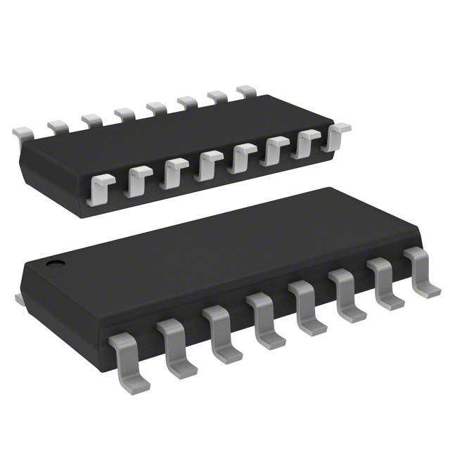
ICGOO电子元器件商城为您提供VSSR1603221JUF由Vishay设计生产,在icgoo商城现货销售,并且可以通过原厂、代理商等渠道进行代购。 VSSR1603221JUF价格参考。VishayVSSR1603221JUF封装/规格:电阻器网络,阵列, 220 Ohm ±5% 100mW Power Per Element Isolated 8 Resistor Network/Array ±100ppm/°C 16-SSOP (0.154", 3.90mm Width)。您可以下载VSSR1603221JUF参考资料、Datasheet数据手册功能说明书,资料中有VSSR1603221JUF 详细功能的应用电路图电压和使用方法及教程。
Vishay Thin Film的VSSR1603221JUF是一款薄膜电阻网络阵列,具有高精度和稳定性,适用于多种电子电路设计。以下是该型号的主要应用场景:

 1. 精密测量与控制
   - 数据采集系统:用于高精度的数据采集电路中,例如传感器信号调理、模数转换器(ADC)前端匹配等。
   - 温度补偿:在温度敏感的电路中,利用其低温度系数特性,确保电路性能稳定。

 2. 电源管理
   - 电压分压器:在电源管理系统中,作为分压网络用于监测和调节电压。
   - 电流检测:通过精确的电阻值实现电流采样,适用于电源模块或功率放大器中的保护电路。

 3. 通信设备
   - 滤波器网络:用于射频(RF)和音频信号处理中的滤波器设计,提供稳定的阻抗匹配。
   - 均衡器与放大器:在通信电路中,用于信号增益调整和平衡。

 4. 工业自动化
   - PLC模块:在可编程逻辑控制器(PLC)中,用于输入/输出信号的调节和保护。
   - 电机驱动:在电机控制电路中,用于电流反馈和电压监控。

 5. 消费电子
   - 音频设备:在音响设备中,用于音量调节、均衡器设置等。
   - 显示驱动:在液晶显示器(LCD)或有机发光二极管(OLED)驱动电路中,用于灰度控制和亮度调节。

 6. 医疗设备
   - 生物信号采集:用于心电图(ECG)、脑电图(EEG)等医疗设备中,确保信号采集的高精度和稳定性。
   - 诊断仪器:在血液分析仪、超声波设备等中,用于信号调理和校准。

 特性优势
- 高精度:±1%的阻值公差,适合需要高精度的场景。
- 低温度系数:±25 ppm/°C的温度系数,保证在不同环境下的稳定性。
- 小型化设计:1603封装尺寸紧凑,适合空间受限的应用。

综上所述,VSSR1603221JUF适用于对精度、稳定性和可靠性要求较高的电子设备和系统中,广泛应用于工业、通信、医疗和消费类电子产品领域。
| 参数 | 数值 |
| 产品目录 | |
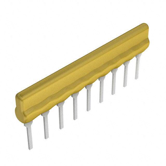
| 描述 | RES ARRAY 220 OHM 8 RES 16SSOP |
| 产品分类 | |
| 品牌 | Vishay Thin Film |
| 数据手册 | |
| 产品图片 |
|
| 产品型号 | VSSR1603221JUF |
| rohs | 无铅 / 符合限制有害物质指令(RoHS)规范要求 |
| 产品系列 | VSSR |
| 产品培训模块 | http://www.digikey.cn/PTM/IndividualPTM.page?site=cn&lang=zhs&ptm=8015 |
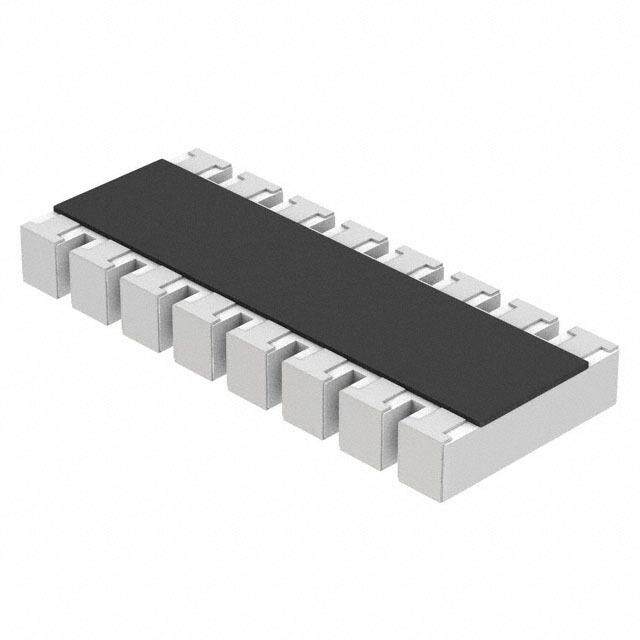
| 产品目录绘图 |
|
| 产品目录页面 | |
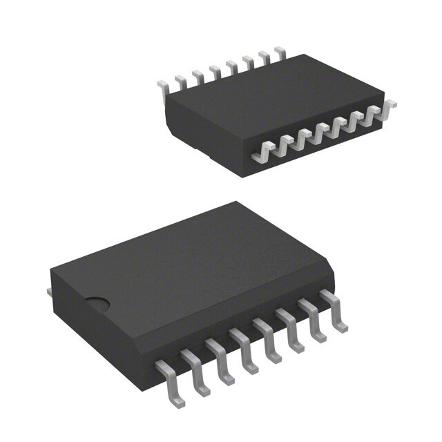
| 供应商器件封装 | 16-SSOP |
| 其它名称 | VSSR16-220-JI |
| 包装 | 管件 |
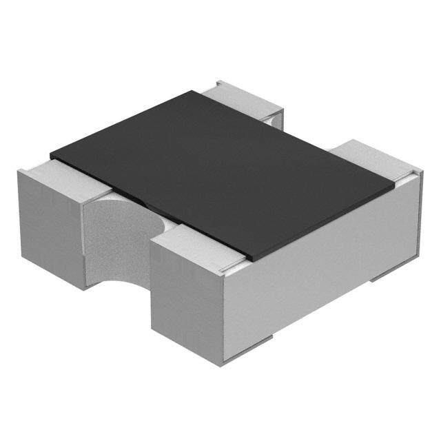
| 大小/尺寸 | 0.193" 长 x 0.154" 宽(4.90mm x 3.91mm) |
| 安装类型 | 表面贴装 |
| 容差 | ±5% |
| 封装/外壳 | 16-SSOP(0.154",3.90mm 宽) |
| 工作温度 | -55°C ~ 125°C |
| 应用 | - |
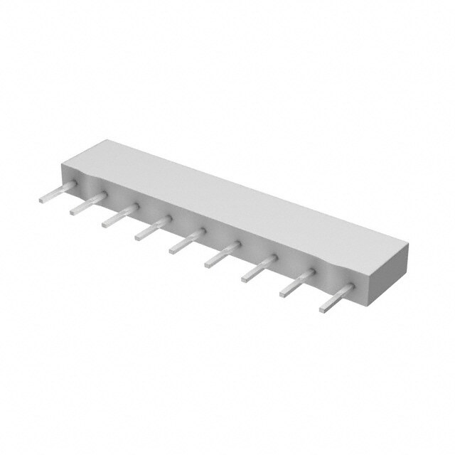
| 引脚数 | 16 |
| 标准包装 | 98 |
| 每元件功率 | 100mW |
| 温度系数 | ±100ppm/°C |
| 电路类型 | 隔离 |
| 电阻(Ω) | 220 |
| 电阻器数 | 8 |
| 高度 | 0.069" (1.76mm) |


- 商务部:美国ITC正式对集成电路等产品启动337调查
- 曝三星4nm工艺存在良率问题 高通将骁龙8 Gen1或转产台积电
- 太阳诱电将投资9.5亿元在常州建新厂生产MLCC 预计2023年完工
- 英特尔发布欧洲新工厂建设计划 深化IDM 2.0 战略
- 台积电先进制程称霸业界 有大客户加持明年业绩稳了
- 达到5530亿美元!SIA预计今年全球半导体销售额将创下新高
- 英特尔拟将自动驾驶子公司Mobileye上市 估值或超500亿美元
- 三星加码芯片和SET,合并消费电子和移动部门,撤换高东真等 CEO
- 三星电子宣布重大人事变动 还合并消费电子和移动部门
- 海关总署:前11个月进口集成电路产品价值2.52万亿元 增长14.8%

PDF Datasheet 数据手册内容提取
VTSR, VSSR, VSOR www.vishay.com Vishay Dale Thin Film Molded, 25 mil or 50 mil Pitch, Dual-In-Line Thin Film Resistor, Surface Mount Network FEATURES • Reduces total assembly costs • Compatible with automatic surface mounting equipment • UL 94 V-0 flame resistant • Thin film tantalum nitride on silicon • Choice of package sizes: VTSR (TSSOP) Actual Size JEDEC® MO-153, VSSR (SSOP or QSOP) Vishay Dale Thin Film resistor networks are designed to be JEDEC MO-137, VSOR (SOIC narrow) JEDEC MS-012 used in either analog or digital circuits. The use of thin film • Moisture sensitivity level 1 (per IPC/JEDEC STD-20C) resistive elements within the network allows you to achieve • Isolated/bussed/dual terminator/differential terminator an infinite number of very low noise and high stability circuit s circuits for industrial, medical and scientific instrumentation. Vishay Dale Thin Film resistor networks are packaged in molded • Material categorization: for definitions of complianc e plastic packages with sizes that are recognized throughout please see www.vishay.com/doc?99912 the world. The rugged packaging offers superio r TYPICAL PERFORMANCE environmental protection and consistent dimensions for ease of placement with automatic SMT equipment. Visha y ABSOLUTE TRACKING Dale Thin Film stocks many designs and values for TCR 100 NA off-the-shelf convenience. With Vishay Dale Thin Film you can depend on quality products delivered on time with ABSOLUTE RATIO service backing the product. TOL. 5, 2, 1 NA SCHEMATICS RESISTORS WITH ONE PIN COMMON 01 SCHEMATIC The 01 circuit provides nominally equal resistors connected between a common pin and a discrete P C board pin. Resistance Range: Commonly used in the following applications: 10 Ω to 47 kΩ • MOS/ROM • TTL input pull-down pull-up/-down • Digital pulse squaring • Open collector pull-up • TTL unused gate pull-up Lead #1 • “Wired OR” pull-up • High speed parallels • Power driven pull-up pull-up Broad selection of standard values available 03 SCHEMATIC ISOLATED RESISTORS The 03 circuit provides nominally equal resistors isolated from all others and wired directly across. Commonly used in the following applications: Resistance Range: 10 Ω to 47 kΩ • “Wired OR” pull-up • Long-line impedance • Power driven pull-up balancing • Power gate pull-up • LED current limiting Lead #1 • Line termination • ECL output pull-down • TTL input pull-down Broad selection of standard values available 05 SCHEMATIC DUAL-LINE TERMINATOR; PULSE SQUARING The 05 circuit contains pairs of resistors connected between ground and a common line. The junctions of these resistor pairs are connected to the input leads. The R1 R1 R1 R1 R1 R1 R1 05 circuits are designed for dual-line termination and puls e R2 R2 R2 R2 R2 R2 R2 squaring. R2 R2 R2 R2 R2 R2 R2 Standard values are: R1 R1 R1 R1 R1 R1 VSSR1605: VSSR2005: R = 220 , R = 330 R = 220 , R = 330 1 2 1 2 Pin 1 R1 = 330 , R2 = 470 R1 = 220 , R2 = 1.8 k R = 1.5 k, R = 3.3 k 1 2 47 SCHEMATIC DIFFERENTIAL TERMINATOR VCC The 47 schematic consists of series resistor sections connected between V and ground. Each contains 3 CC resistors of 2 different resistance values. R1 Standard values are: R VSSR20 and VTSR20: VSSR16 and VTSR16: 2 R R1 = 270 , R2 = 120 R1 = 330 , R2 = 150 3 R1 = 330 , R2 = 220 Lead #1 GND Revision: 01-Mar-2019 1 Document Number: 60003 For technical questions, contact: thinfilm@vishay.com THIS DOCUMENT IS SUBJECT TO CHANGE WITHOUT NOTICE. THE PRODUCTS DESCRIBED HEREIN AND THIS DOCUMENT ARE SUBJECT TO SPECIFIC DISCLAIMERS, SET FORTH AT www.vishay.com/doc?91000
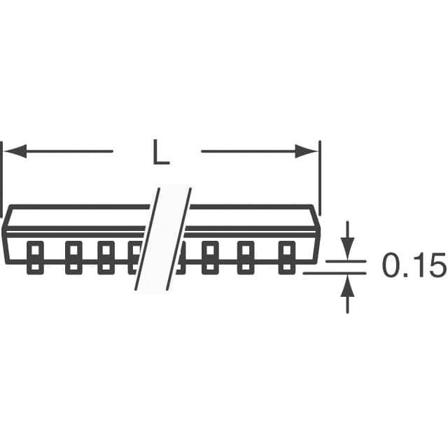
VTSR, VSSR, VSOR www.vishay.com Vishay Dale Thin Film STANDARD ELECTRICAL SPECIFICATIONS TEST SPECIFICATIONS CONDITIONS Material Tantalum nitride - Pin / Lead Number 16, 20, 24 - Resistance Range 10 to 47 k Per E-24 table TCR: Absolute ± 100 ppm/°C -55 °C to +125 °C TCR: Tracking n/a - ± 5 % standard (± 2 % available) Per E-24 table Tolerance: Absolute ± 1 % standard (check factory) Per E-96 table Tolerance: Ratio NA - Power Rating: Resistor 100 mW max. At +70 °C Power Rating: Package 16 = 1.0 W, 20 = 1.2 W, 24 = 1.4 W 0 °C to +70 °C Stability: Absolute - - Stability: Ratio - - Voltage Coefficient 5 ppm/V (typical) - Working Voltage 50 V - DC Operating Temperature Range -55 °C to +125 °C - Storage Temperature Range -55 °C to +150 °C - Noise < -35 dB - Thermal EMF - - Shelf Life Stability: Absolute - - Shelf Life Stability: Ratio - - DIMENSIONS AND IMPRINTING in inches (millimeters) Part Marking-Model, Pin Count (Optional), Schematic B C E Resistance Value xxxx Code F H Date G Code Pin #1 J A W D DIMENSION VTSR-xxxx VSSR-xxxx VSOR-xxxx A - 16 PIN 0.206 ± 0.003 (5.23 ± 0.08) 0.193 ± 0.004 (4.90 ± 0.010) 0.390 ± 0.010 (9.91 ± 0.25) A - 20 PIN 0.256 ± 0.003 (6.50 ± 0.08) 0.341 ± 0.003 (8.66 ± 0.08) NA A - 24 PIN 0.306 ± 0.003 (7.77 ± 0.08) 0.341 ± 0.003 (8.66 ± 0.08) NA B (Ref.) 0.0256 (0.65) 0.025 (0.64) 0.050 (1.27) C (Ref.) 0.0087 (0.22) 0.010 (0.25) 0.016 (0.41) D 0.004 (0.10) 0.006 (0.15) 0.008 (0.20) E (Typ.) 0.024 (0.61) 0.025 (0.64) 0.030 (0.76) F 0.173 ± 0.003 (4.39 ± 0.08) 0.154 ± 0.003 (3.91 ± 0.08) 0.152 ± 0.003 (3.86 ± 0.08) G 0.015 × 45° (0.38) 0.015 × 45° (0.38) 0.015 × 45° (0.38) H 0.252 ± 0.005 (6.40 ± 0.13) 0.236 ± 0.008 (5.99 ± 0.20) 0.236 ± 0.005 (5.99 ± 0.13) J (Ref.) 0.005 (0.13) 0.010 (0.25) 0.008 (0.20) W 0.043 ± 0.005 (1.09 ± 0.13) 0.064 ± 0.005 (1.63 ± 0.13) 0.064 ± 0.005 (1.63 ± 0.13) MARKING PIN COUNT MODEL SCHEMATIC RESISTANCE RESISTANCE DATE CODE (Optional) VXXX XX XX XXXX XXX XXXX VSOR 16 01, 03, 1 % RESISTANCE OR 1 %, 2 %, 5 % RESISTANCE VSSR 20 05 or 47 e.g.: 43R2 e.g.: 103 = 10K VTSR 24 4 digits are used to express The first 2 digits are significant ohmic values only less than figures, the last digit specifies 100 . R is used to designate the number of zeros to follow. the decimal position Revision: 01-Mar-2019 2 Document Number: 60003 For technical questions, contact: thinfilm@vishay.com THIS DOCUMENT IS SUBJECT TO CHANGE WITHOUT NOTICE. THE PRODUCTS DESCRIBED HEREIN AND THIS DOCUMENT ARE SUBJECT TO SPECIFIC DISCLAIMERS, SET FORTH AT www.vishay.com/doc?91000
VTSR, VSSR, VSOR www.vishay.com Vishay Dale Thin Film MECHANICAL SPECIFICATIONS Resistive Element Tantalum nitride Substrate Material Silicon Body Molded epoxy Terminals Copper alloy Plating 100 % matte tin Lead Coplanarity 0.0005" Marking Resistance to Solvents Permanency testing per MIL-STD-202, method 215 PACKAGING INFORMATION DERATING CURVE MODEL LEADS TAPE AND REEL TUBES 100 er 16 2500 94 w 80 o P VTSR (TSSOP) 20 2500 74 d e 60 at 24 2500 62 R of 40 16 2500 98 nt e c 20 e VSSR (QSOP) 20 2500 55 Pr 0 24 2500 55 0 70 125 150 16 2500 48 Ambient Temperature °C VSOR (SOIC) 20 1000 38 GLOBAL PART NUMBER INFORMATION New Global Part Numbering: VTSR1601103JTF V T S R 1 6 0 1 1 0 3 J T F V S O R 1 6 0 5 3 3 1 4 7 1 G T F RESISTANCE GLOBAL MODEL PIN COUNT SCHEMATIC TOLERANCE PACKAGING (3, 4 or 6 digits) VTSR 16 01 (bussed) XXX: 100R and all 1 %, F = 1.0 % TAPE AND REEL VSSR 20 03 (isolated) 2 % and 5 % G = 2.0 % TF = full reel 2500 VSOR 24 (not VSOR) First 2 digits are significan t J = 5.0 % UF = tubed Lead (Pb)-free (e3) figures. Last digit specifies date code > 2705 number of zeros to follow. XXXX: < 100R 1 % First 3 digits are significan t figures. Last digit specifies number of zeros to follow. 16 (not VTSR) 05 (terminator) xxx xxx G = 2.0 % 20 47 (terminator) First 2 digits are significan t J = 5.0 % figures. Last digit specifies number of zeros. Historical Part Number example: VSSR2001102GT/R (for reference purposes only) VSSR 20 01 102 G T/R MODEL PIN COUNT SCHEMATIC RESISTANCE TOLERANCE PACKAGING Revision: 01-Mar-2019 3 Document Number: 60003 For technical questions, contact: thinfilm@vishay.com THIS DOCUMENT IS SUBJECT TO CHANGE WITHOUT NOTICE. THE PRODUCTS DESCRIBED HEREIN AND THIS DOCUMENT ARE SUBJECT TO SPECIFIC DISCLAIMERS, SET FORTH AT www.vishay.com/doc?91000
Legal Disclaimer Notice www.vishay.com Vishay Disclaimer ALL PRODUCT, PRODUCT SPECIFICATIONS AND DATA ARE SUBJECT TO CHANGE WITHOUT NOTICE TO IMPROV E RELIABILITY, FUNCTION OR DESIGN OR OTHERWISE. Vishay Intertechnology, Inc., its affiliates, agents, and employees, and all persons acting on its or their behalf (collectively, “Vishay”), disclaim any and all liability for any errors, inaccuracies or incompleteness contained in any datasheet or in any other disclosure relating to any product. Vishay makes no warranty, representation or guarantee regarding the suitability of the products for any particular purpose o r the continuing production of any product. To the maximum extent permitted by applicable law, Vishay disclaims (i) any and all liability arising out of the application or use of any product, (ii) any and all liability, including without limitation special, consequential or incidental damages, and (iii) any and all implied warranties, including warranties of fitness for particular purpose, non-infringement and merchantability. Statements regarding the suitability of products for certain types of applications are based on Vishay’s knowledge of typical requirements that are often placed on Vishay products in generic applications. Such statements are not binding statements about the suitability of products for a particular application. It is the customer’s responsibility to validate that a particular product with the properties described in the product specification is suitable for use in a particular application. Parameters provided in datasheets and / or specifications may vary in different applications and performance may vary over time. All operating parameters, including typical parameters, must be validated for each customer application by the customer’s technical experts. Product specifications do not expand or otherwise modify Vishay’s terms and conditions of purchase, including but not limited to the warranty expressed therein. Except as expressly indicated in writing, Vishay products are not designed for use in medical, life-saving, or life-sustainin g applications or for any other application in which the failure of the Vishay product could result in personal injury or death. Customers using or selling Vishay products not expressly indicated for use in such applications do so at their own risk . Please contact authorized Vishay personnel to obtain written terms and conditions regarding products designed for such applications. No license, express or implied, by estoppel or otherwise, to any intellectual property rights is granted by this documen t or by any conduct of Vishay. Product names and markings noted herein may be trademarks of their respective owners. © 2019 VISHAY INTERTECHNOLOGY, INC. ALL RIGHTS RESERVED Revision: 01-Jan-2019 1 Document Number: 91000