ICGOO在线商城 > 分立半导体产品 > 二极管 - 整流器 - 单 > VS-12FR120
 Datasheet下载
- 型号: VS-12FR120
- 制造商: Vishay
- 库位|库存: xxxx|xxxx
- 要求:
| 数量阶梯 | 香港交货 | 国内含税 |
| +xxxx | $xxxx | ¥xxxx |
查看当月历史价格
查看今年历史价格
VS-12FR120产品简介:
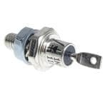
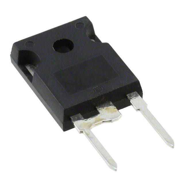
ICGOO电子元器件商城为您提供VS-12FR120由Vishay设计生产,在icgoo商城现货销售,并且可以通过原厂、代理商等渠道进行代购。 VS-12FR120价格参考。VishayVS-12FR120封装/规格:二极管 - 整流器 - 单, 标准型, 反极性 底座,接线柱安装 二极管 1200V 12A DO-203AA。您可以下载VS-12FR120参考资料、Datasheet数据手册功能说明书,资料中有VS-12FR120 详细功能的应用电路图电压和使用方法及教程。
Vishay Semiconductor Diodes Division生产的VS-12FR120是一款单整流二极管,属于高电压、大电流的快速恢复整流器。该器件额定重复峰值反向电压(VRRM)为1200V,正向平均整流电流(IF(AV))可达12A,具有较低的正向导通压降和快速恢复特性,适用于高效率电源转换系统。

VS-12FR120主要应用于工业与电力电子领域,如开关电源(SMPS)、不间断电源(UPS)、逆变器、电机驱动和电焊机等设备中,用于实现交流到直流的整流功能。其高耐压和高电流能力使其在高压直流电源和大功率整流电路中表现出色。此外,该二极管也可用于感应加热、电源适配器和太阳能逆变器等需要高效能整流元件的场合。

由于采用TO-247封装,VS-12FR120具备良好的热性能和机械稳定性,便于安装在散热器上,适合在高温和高负载环境下稳定运行。其可靠性高,符合工业级应用要求,广泛用于对电源效率和系统稳定性有较高要求的工业控制系统和能源转换装置中。
| 参数 | 数值 |
| 产品目录 | |
| 描述 | DIODE GEN PURP 1.2KV 12A DO203AA |
| 产品分类 | 单二极管/整流器 |
| 品牌 | Vishay Semiconductor Diodes Division |
| 数据手册 | |
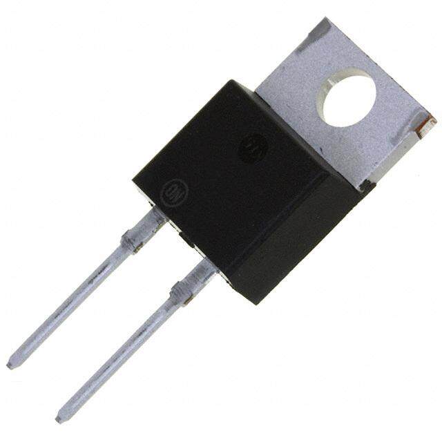
| 产品图片 |
|
| 产品型号 | VS-12FR120 |
| rohs | 无铅 / 符合限制有害物质指令(RoHS)规范要求 |
| 产品系列 | - |
| 不同If时的电压-正向(Vf) | 1.26V @ 38A |
| 不同 Vr、F时的电容 | - |
| 不同 Vr时的电流-反向漏电流 | 12mA @ 1200V |
| 二极管类型 | 标准 |
| 供应商器件封装 | DO-203AA |
| 其它名称 | *12FR120 |
| 包装 | 散装 |
| 反向恢复时间(trr) | - |
| 安装类型 | 底座,接线柱安装 |
| 封装/外壳 | DO-203AA,DO-4,接线柱 |
| 工作温度-结 | -65°C ~ 175°C |
| 标准包装 | 100 |
| 热阻 | 0.5°C/W Cs |
| 电压-DC反向(Vr)(最大值) | 1200V(1.2kV) |
| 电流-平均整流(Io) | 12A |
| 速度 | 标准恢复 >500ns,> 200mA(Io) |


PDF Datasheet 数据手册内容提取
VS-12F(R) Series www.vishay.com Vishay Semiconductors Standard Recovery Diodes, (Stud Version), 12 A FEATURES • High surge current capability • Stud cathode and stud anode version • Wide current range • Types up to 1200 V V RRM • Designed and qualified for industrial and consumer level DO-4 (DO-203AA) • Material categorization: for definitions of compliance please see www.vishay.com/doc?99912 TYPICAL APPLICATIONS PRIMARY CHARACTERISTICS • Battery charges I 12 A F(AV) • Converters Package DO-4 (DO-203AA) Circuit configuration Single • Power supplies • Machine tool controls MAJOR RATINGS AND CHARACTERISTICS PARAMETER TEST CONDITIONS VALUES UNITS 12 A I F(AV) T 144 °C C I 19 A F(RMS) 50 Hz 265 I A FSM 60 Hz 280 50 Hz 351 I2t A2s 60 Hz 320 V Range 100 to 1200 V RRM T -65 to +175 °C J ELECTRICAL SPECIFICATIONS VOLTAGE RATINGS V , MAXIMUM V , MAXIMUM RRM RSM I MAXIMUM TYPE VOLTAGE REPETITIVE PEAK NON-REPETITIVE RRM AT T = 175 °C NUMBER CODE REVERSE VOLTAGE PEAK VOLTAGE J mA V V 10 100 150 20 200 275 40 400 500 VS-12F(R) 60 600 725 12 80 800 950 100 1000 1200 120 1200 1400 Revision: 11-Jan-18 1 Document Number: 93487 For technical questions within your region: DiodesAmericas@vishay.com, DiodesAsia@vishay.com, DiodesEurope@vishay.com THIS DOCUMENT IS SUBJECT TO CHANGE WITHOUT NOTICE. THE PRODUCTS DESCRIBED HEREIN AND THIS DOCUMENT ARE SUBJECT TO SPECIFIC DISCLAIMERS, SET FORTH AT www.vishay.com/doc?91000
VS-12F(R) Series www.vishay.com Vishay Semiconductors FORWARD CONDUCTION PARAMETER SYMBOL TEST CONDITIONS VALUES UNITS Maximum average forward current 12 A I 180° conduction, half sine wave at case temperature F(AV) 144 °C Maximum RMS forward current I 19 A F(RMS) t = 10 ms No voltage 265 Maximum peak, one-cycle forward, t = 8.3 ms reapplied 280 I A non-repetitive surge current FSM t = 10 ms 100 % VRRM 225 t = 8.3 ms reapplied Sinusoidal half wave, 235 t = 10 ms No voltage initial TJ = TJ maximum 351 t = 8.3 ms reapplied 320 Maximum I2t for fusing I2t A2s t = 10 ms 100 % VRRM 250 t = 8.3 ms reapplied 226 Maximum I2t for fusing I2t t = 0.1 to 10 ms, no voltage reapplied 3510 A2s Low level value of threshold voltage VF(TO)1 (16.7 % x x IF(AV) < I < x IF(AV)), TJ = TJ maximum 0.77 V High level value of threshold voltage VF(TO)2 (I > x IF(AV)), TJ = TJ maximum 0.97 Low level value of forward slope resistance rf1 (16.7 % x x IF(AV) < I < x IF(AV)), TJ = TJ maximum 10.70 m High level value of forward slope resistance rf2 (I > x IF(AV)), TJ = TJ maximum 6.20 Maximum forward voltage drop V I = 38 A, T = 25 °C, t = 400 μs rectangular wave 1.26 V FM pk J p THERMAL AND MECHANICAL SPECIFICATIONS PARAMETER SYMBOL TEST CONDITIONS VALUES UNITS Maximum junction operating temperature range T -65 to +175 J °C Maximum storage temperature range T -65 to +200 Stg Maximum thermal resistance, junction to case R DC operation 2 thJC K/W Maximum thermal resistance, case to heatsink R Mounting surface, smooth, flat and greased 0.5 thCS 1.5 + 0 - 10 % N · m Not lubricated threads 13 lbf · in Allowable mounting torque 1.2 + 0 - 10 % N · m Lubricated threads 10 lbf · in 7 g Approximate weight 0.25 oz. Case style See dimensions - link at the end of datasheet DO-4 (DO-203AA) R CONDUCTION thJC CONDUCTION ANGLE SINUSOIDAL CONDUCTION RECTANGULAR CONDUCTION TEST CONDITIONS UNITS 180° 0.33 0.26 120° 0.41 0.44 90° 0.53 0.58 T = T maximum K/W J J 60° 0.78 0.81 30° 1.28 1.29 Note • The table above shows the increment of thermal resistance R when devices operate at different conduction angles than DC thJC Revision: 11-Jan-18 2 Document Number: 93487 For technical questions within your region: DiodesAmericas@vishay.com, DiodesAsia@vishay.com, DiodesEurope@vishay.com THIS DOCUMENT IS SUBJECT TO CHANGE WITHOUT NOTICE. THE PRODUCTS DESCRIBED HEREIN AND THIS DOCUMENT ARE SUBJECT TO SPECIFIC DISCLAIMERS, SET FORTH AT www.vishay.com/doc?91000
VS-12F(R) Series www.vishay.com Vishay Semiconductors 180 180 12F(R) Series 12F(R) Series R t h J C (DC) = 2.0 K/W R t h J C (DC) = 2.0 K/W aximum Allowable se Temperature (°C) 116700 Conduction Angle ximum Allowable e Temperature (°C) 111567000 30° 60° Conduction Period Ma 150 as C Ma 140 90° 30° 60° C 120° 90° 120° 180° 180° DC 140 130 0 2 4 6 8 10 12 14 0 4 8 12 16 20 Average Forward Current (A) Average Forward Current (A) Fig. 1 - Current Ratings Characteristics Fig. 2 - Current Ratings Characteristics 14 Forward W) 1102 118296300000°°°°° 151K2/KW/W10K/W RthSA=8K/W6-KD/WeltaR age oss ( 8 RMS Limit 20K/W erL Aver 6 30K/W m ow Conduction Angle uP 4 m xi 12F(R) Series a 2 M T = 175°C J 0 0 2 4 6 8 10 12 1 4 25 50 75 100 Average Forward Current (A) Maximum Allowable Ambient Temperature (°C) Fig. 3 - Forward Power Loss Characteristics 20 DC R verage Forward r Loss (W) 1126 118296300000°°°°° 111520KK8K/W/KW/W/WthSA=6K/W-DeltaR m Awe 8 RMS Limit 20K/W o Conduction Period muP 30K/W axi 4 12F(R) Series M TJ = 175°C 0 0 4 8 12 16 20 25 50 75 100 Average Forward Current (A) Maximum Allowable Ambient Temperature (°C) Fig. 4 - Forward Power Loss Characteristics Revision: 11-Jan-18 3 Document Number: 93487 For technical questions within your region: DiodesAmericas@vishay.com, DiodesAsia@vishay.com, DiodesEurope@vishay.com THIS DOCUMENT IS SUBJECT TO CHANGE WITHOUT NOTICE. THE PRODUCTS DESCRIBED HEREIN AND THIS DOCUMENT ARE SUBJECT TO SPECIFIC DISCLAIMERS, SET FORTH AT www.vishay.com/doc?91000
VS-12F(R) Series www.vishay.com Vishay Semiconductors ward Current (A) 222025050 ARta Atendy VR Ra Rt e M d ALpopaldie Cd oFno@@dllioI tn65iwoi00tnii naHH gAl zz TnS J 00d u=.. 00rW g011ei807t.h305 °ssC ward Current (A) 1010000 TJ = 25°C TJ = 175°C Wave For 115705 ous For 10 e e n n a Si 125 nt 12F(R) Series alf 12F(R) Series sta H n ak 100 1 10 100 I 10 1 2 3 4 5 6 e P Number Of Equal Amplitude Half Cycle Current Pulses (N) Instantaneous Forward Voltage (V) Fig. 5 - Maximum Non-Repetitive Surge Current Fig. 7 - Forward Voltage Drop Characteristics A) 275 W) 10 nt ( Maximum NoVne Rrseupse Ptiutilvsee STurargine DCuurrarteionnt. C/ Steady State Value urre 250 No VoInltiatigael TRJ e=a p1p75lie°Cd ce (° R(D t Ch J CO =p e2r.a0t iKon/W) d C 225 Rated VR R M Reapplied dan war 200 mpe r e Fo 175 mal I 1 alf Sine Wav 112550 12F(R) Series nsient Ther 12F(R) Series H a k 100 Tr 0.1 ea 0.01 0.1 1 -C 0.001 0.01 0.1 1 10 P J Pulse Train Duration (s) Zth Square Wave Pulse Duration (s) Fig. 6 - Maximum Non-Repetitive Surge Current Fig. 8 - Thermal Impedance Z Characteristics thJC ORDERING INFORMATION TABLE Device code VS- 12 F R 120 M 1 2 3 4 5 6 1 - Vishay Semiconductors product 2 - Current rating: code = I F(AV) 3 - F = standard device 4 - None= stud normal polarity (cathode to stud) R = stud reverse polarity (anode to stud) 5 - Voltage code x 10 = V (see Voltage Ratings table) RRM 6 - None= stud base DO-4 (DO-203AA) 10-32UNF-2A M = stud base DO-4 (DO-203AA) M5 x 0.8 LINKS TO RELATED DOCUMENTS Dimensions www.vishay.com/doc?95311 Revision: 11-Jan-18 4 Document Number: 93487 For technical questions within your region: DiodesAmericas@vishay.com, DiodesAsia@vishay.com, DiodesEurope@vishay.com THIS DOCUMENT IS SUBJECT TO CHANGE WITHOUT NOTICE. THE PRODUCTS DESCRIBED HEREIN AND THIS DOCUMENT ARE SUBJECT TO SPECIFIC DISCLAIMERS, SET FORTH AT www.vishay.com/doc?91000
Outline Dimensions Vishay Semiconductors DO-203AA (DO-4) DIMENSIONS in millimeters (inches) 3.30 (0.13) 0.8 ± 0.1 4.00 (0.16) (0.03 ± 0.004) 2 + 0.3 0 (0.08 + 0 . 0 1 ) 0 5.50 (0.22) MIN. R 0.40 Ø 1.80 ± 0.20 R (0.02) (Ø 0.07 ± 0.01) 20.30 (0.80) MAX. 10.20 (0.40) Ø 6.8 (0.27) MAX. 3.50 (0.14) 11.50 (0.45) 10.70 (0.42) 10/32" UNF-2A For metric devices: M5 x 0.8 11 (0.43) Document Number: 95311 For technical questions, contact: indmodules@vishay.com www.vishay.com Revision: 30-Jun-08 1
Legal Disclaimer Notice www.vishay.com Vishay Disclaimer ALL PRODUCT, PRODUCT SPECIFICATIONS AND DATA ARE SUBJECT TO CHANGE WITHOUT NOTICE TO IMPROVE RELIABILITY, FUNCTION OR DESIGN OR OTHERWISE. Vishay Intertechnology, Inc., its affiliates, agents, and employees, and all persons acting on its or their behalf (collectively, “Vishay”), disclaim any and all liability for any errors, inaccuracies or incompleteness contained in any datasheet or in any other disclosure relating to any product. Vishay makes no warranty, representation or guarantee regarding the suitability of the products for any particular purpose or the continuing production of any product. To the maximum extent permitted by applicable law, Vishay disclaims (i) any and all liability arising out of the application or use of any product, (ii) any and all liability, including without limitation special, consequential or incidental damages, and (iii) any and all implied warranties, including warranties of fitness for particular purpose, non-infringement and merchantability. Statements regarding the suitability of products for certain types of applications are based on Vishay’s knowledge of typical requirements that are often placed on Vishay products in generic applications. Such statements are not binding statements about the suitability of products for a particular application. It is the customer’s responsibility to validate that a particular product with the properties described in the product specification is suitable for use in a particular application. Parameters provided in datasheets and / or specifications may vary in different applications and performance may vary over time. All operating parameters, including typical parameters, must be validated for each customer application by the customer’s technical experts. Product specifications do not expand or otherwise modify Vishay’s terms and conditions of purchase, including but not limited to the warranty expressed therein. Except as expressly indicated in writing, Vishay products are not designed for use in medical, life-saving, or life-sustaining applications or for any other application in which the failure of the Vishay product could result in personal injury or death. Customers using or selling Vishay products not expressly indicated for use in such applications do so at their own risk. Please contact authorized Vishay personnel to obtain written terms and conditions regarding products designed for such applications. No license, express or implied, by estoppel or otherwise, to any intellectual property rights is granted by this document or by any conduct of Vishay. Product names and markings noted herein may be trademarks of their respective owners. © 2017 VISHAY INTERTECHNOLOGY, INC. ALL RIGHTS RESERVED Revision: 08-Feb-17 1 Document Number: 91000
Mouser Electronics Authorized Distributor Click to View Pricing, Inventory, Delivery & Lifecycle Information: V ishay: VS-12FR10 VS-12F40 12F60M VS-12FR120 VS-12F10 VS-12F100 VS-12F120 VS-12F20 VS-12F60 VS-12F80 VS-12FR100 VS-12FR20 VS-12FR40 VS-12FR60 VS-12FR80 VS-12F120M