ICGOO在线商城 > 电感器,线圈,扼流圈 > 固定值电感器 > VLF5014AT-220MR62
 Datasheet下载
- 型号: VLF5014AT-220MR62
- 制造商: TDK
- 库位|库存: xxxx|xxxx
- 要求:
| 数量阶梯 | 香港交货 | 国内含税 |
| +xxxx | $xxxx | ¥xxxx |
查看当月历史价格
查看今年历史价格
VLF5014AT-220MR62产品简介:
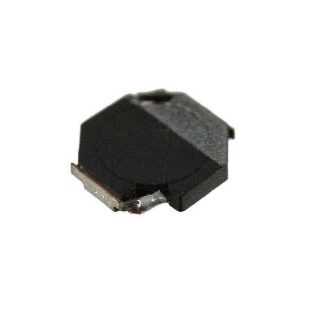
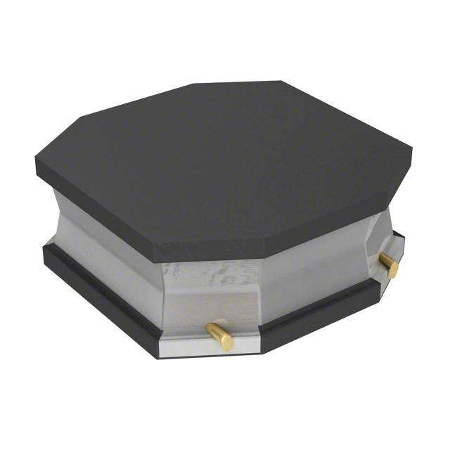
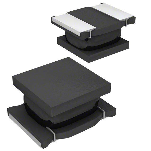
ICGOO电子元器件商城为您提供VLF5014AT-220MR62由TDK设计生产,在icgoo商城现货销售,并且可以通过原厂、代理商等渠道进行代购。 VLF5014AT-220MR62价格参考。TDKVLF5014AT-220MR62封装/规格:固定值电感器, 22µH Shielded Wirewound Inductor 620mA 460mOhm Max Nonstandard 。您可以下载VLF5014AT-220MR62参考资料、Datasheet数据手册功能说明书,资料中有VLF5014AT-220MR62 详细功能的应用电路图电压和使用方法及教程。
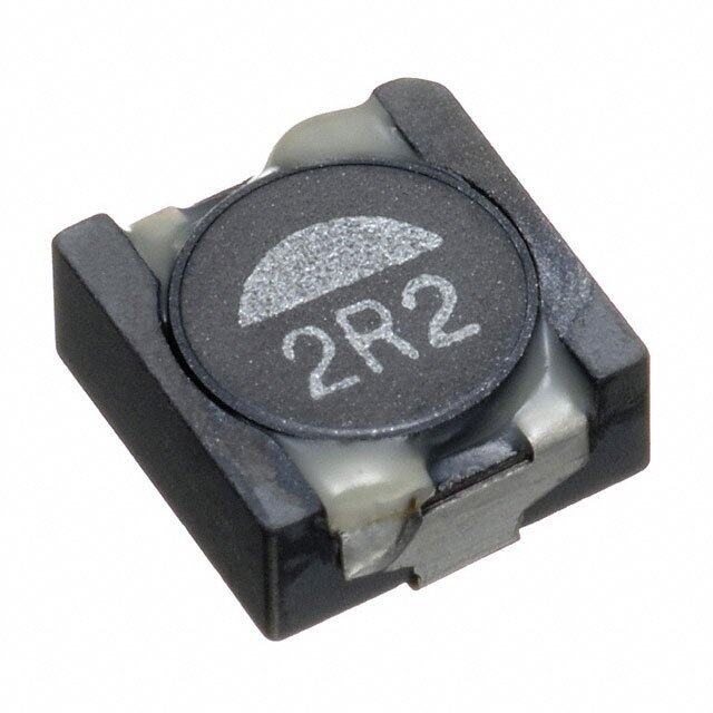
TDK Corporation的VLF5014AT-220MR62是一款固定值电感器,属于VLF系列,具有小型化、高效率和低损耗的特点。该电感器主要应用于便携式电子设备和高密度电路设计中。其典型应用场景包括智能手机、平板电脑、笔记本电脑等消费类电子产品中的电源管理模块,如DC-DC转换器,用于稳定电压输出并提升电源转换效率。此外,该器件也适用于无线充电模块、可穿戴设备及物联网终端等对空间和功耗要求严苛的场合。由于其具备良好的磁屏蔽性能和抗干扰能力,VLF5014AT-220MR62还能有效减少电磁噪声,提高系统稳定性。同时,它也可用于各类小型化电源适配器、LED驱动电路以及工业控制设备中的信号滤波与能量存储环节。总体而言,该电感器凭借其紧凑尺寸(5.0×5.0×1.4 mm)、额定电感值22μH和较高饱和电流特性,广泛服务于高频开关电源环境,在确保可靠性和高效能的同时,满足现代电子产品轻薄化、低功耗的发展需求。
| 参数 | 数值 |
| 产品目录 | |
| DC电阻(DCR) | 460 毫欧最大 |
| 描述 | INDUCTOR POWER 22UH .62A SMD固定电感器 22uH 0.46ohms 0.81A |
| 产品分类 | |
| 品牌 | TDK |
| 产品手册 | |
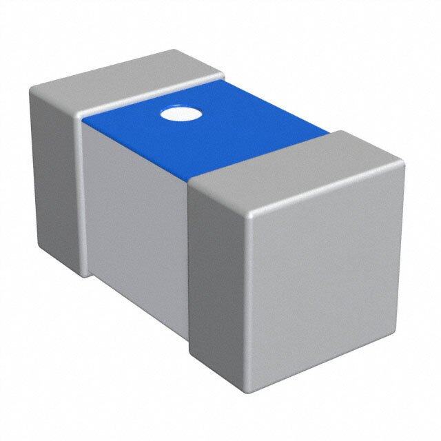
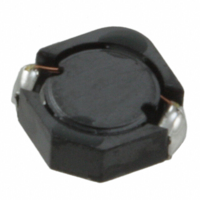
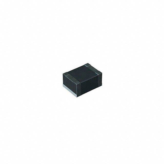
| 产品图片 |
|
| rohs | 符合RoHS无铅 / 符合限制有害物质指令(RoHS)规范要求 |
| 产品系列 | 固定电感器,TDK VLF5014AT-220MR62VLF |
| 数据手册 | |
| 产品型号 | VLF5014AT-220MR62 |
| 不同频率时的Q值 | - |
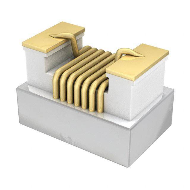
| 产品目录绘图 |
|
| 产品目录页面 | |
| 产品种类 | 固定电感器 |
| 供应商器件封装 | - |
| 其它名称 | 445-4195-2 |
| 包装 | 带卷 (TR) |
| 商标 | TDK |
| 外壳宽度 | 4.7 mm |
| 外壳长度 | 4.5 mm |
| 外壳高度 | 1.4 mm |
| 大小/尺寸 | 0.185" 长x 0.177" 宽(4.70mm x 4.50mm) |
| 安装类型 | 表面贴装 |
| 容差 | 20 % |
| 封装 | Reel |
| 封装/外壳 | 非标准 |
| 屏蔽 | 屏蔽 |
| 工作温度 | -40°C ~ 105°C |
| 工作温度范围 | - 40 C to + 105 C |
| 工厂包装数量 | 1000 |
| 最大直流电流 | 620 mA |
| 最大直流电阻 | 460 mOhms |
| 材料-磁芯 | - |
| 标准包装 | 1,000 |
| 测试频率 | 100 kHz |
| 电感 | 22 uH |
| 电流-饱和值 | 810mA |
| 端接类型 | SMD/SMT |
| 类型 | 绕线 |
| 系列 | VLF |
| 频率-测试 | 100kHz |
| 频率-自谐振 | - |
| 额定电流 | 620mA |
| 高度-安装(最大值) | 0.055"(1.40mm) |


A%20Series%20Top.jpg)

A%20Series%20Footprint.jpg)


PDF Datasheet 数据手册内容提取
(1/2) SMD Inductors(Coils) Conformity to RoHS Directive For Power Line(Wound, Magnetic Shielded) VLF Series VLF5014A FEATURES SHAPES AND DIMENSIONS (cid:127) Miniature size Mount area: 4.5×4.7mm 3 4 0. R ± Low profile: 1.4mm max. height 7 5 4. (cid:127) Generic use for portable DC to DC converter line. (cid:127) High magnetic shield construction should actualize high resolu- 4.7±0.3 1.4max. tion for EMC protection. Dimensions in mm (cid:127) Available for automatic mounting in tape and real package. (cid:127) The products contain no lead and also support lead-free RECOMMENDED PC BOARD PATTERN soldering. 6 (cid:127) It is a product conforming to RoHS directive. 1. 3.9 APPLICATIONS 5.7 Dimensions in mm Power souce inductor for mobile devices such as mobile phones, HDDs, and DSCs ELECTRICAL CHARACTERISTICS Inductance DC resistance(Ω) Rated current∗1(A) Inductance Test frequency Part No. [at 1/2 Idc1]∗2 Based on inductance Based on temperature tolerance(%) (kHz) max. typ. (µH) change Idc1 max. rise Idc2 typ. VLF5014AT-1R5M1R7 1.5 ±20 100 0.059 0.051 2.9 1.7 VLF5014AT-2R7M1R5 2.7 ±20 100 0.078 0.068 2.2 1.5 VLF5014AT-4R7M1R1 4.7 ±20 100 0.13 0.12 1.7 1.1 VLF5014AT-6R8MR99 6.8 ±20 100 0.19 0.16 1.4 0.99 VLF5014AT-100MR92 10 ±20 100 0.22 0.19 1.1 0.92 VLF5014AT-150MR76 15 ±20 100 0.32 0.28 0.97 0.76 VLF5014AT-220MR62 22 ±20 100 0.46 0.40 0.81 0.62 VLF5014AT-330MR50 33 ±20 100 0.72 0.63 0.64 0.50 VLF5014AT-470MR41 47 ±20 100 1.1 0.95 0.54 0.41 VLF5014AT-101MR26 100 ±20 100 2.7 2.4 0.37 0.26 ∗1 Rated current: Value obtained when current flows and the temperature has risen to 40°C or when DC current flows and the nominal value of inductance has fallen by 30%, whichever is smaller. ∗2Inductance is at 1/2 Idc1 power distribution. The L vaule at 0A is higher than the guaranteed performance. (cid:127) Operating temperature range: –40 to +105°C (Including self-temperature rise) TYPICAL ELECTRICAL CHARACTERISTICS INDUCTANCE vs. DC SUPERPOSITION CHARACTERISTICS VLF5014AT-1R5M1R7 VLF5014AT-2R7M1R5 2.0 4.0 )H1.5 )H3.0 µ µ (e (e c c n1.0 n2.0 a a ct ct u u d d In0.5 In1.0 0.0 0.0 0 500 1000 1500 2000 2500 3000 3500 0 500 1000 1500 2000 2500 3000 DC current(mA) DC current(mA) (cid:127) Conformity to RoHS Directive: This means that, in conformity with EU Directive 2002/95/EC, lead, cadmium, mercury, hexavalent chromium, and specific bromine-based flame retardants, PBB and PBDE, have not been used, except for exempted applications. • All specifications are subject to change without notice. 003-04 / 20080822 / e531_vlf5014a.fm
(2/2) TYPICAL ELECTRICAL CHARACTERISTICS INDUCTANCE vs. DC SUPERPOSITION CHARACTERISTICS VLF5014AT-4R7M1R1 VLF5014AT-6R8MR99 6 10 5 8 )H )H µ 4 µ (e (e 6 nc 3 nc a a duct 2 duct 4 n n I I 2 1 0 0 0 500 1000 1500 2000 0 200 400 600 800 1000 1200 1400 1600 1800 DC current(mA) DC current(mA) VLF5014AT-100MR92 VLF5014AT-150MR76 14 25 12 20 )H10 )H µ(Inductance 468 µ(Inductance11505 2 0 0 0 200 400 600 800 1000 1200 1400 0 200 400 600 800 1000 1200 DC current(mA) DC current(mA) VLF5014AT-220MR62 VLF5014AT-330MR50 25 50 20 40 )H )H µ µ (e15 (e30 nc nc a a uct10 uct20 d d n n I 5 I10 0 0 0 200 400 600 800 1000 0 200 400 600 800 DC current(mA) DC current(mA) VLF5014AT-470MR41 VLF5014AT-101MR26 80 150 )H60 )H µ µ100 (e (e c c n40 n a a ct ct du du 50 In20 In 0 0 0 100 200 300 400 500 600 700 0 100 200 300 400 500 DC current(mA) DC current(mA) TEST CIRCUIT C=20,000µF A L=0.1H 2 Sample 1 1: LCR meter 4285A f=100kHz 2: DC constant current (cid:127) All specifications are subject to change without notice. 003-04 / 20080822 / e531_vlf5014a.fm