ICGOO在线商城 > VFB600-D48-S12
 Datasheet下载
- 型号: VFB600-D48-S12
- 制造商: CUI/STACK INCORPORATED
- 库位|库存: xxxx|xxxx
- 要求:
| 数量阶梯 | 香港交货 | 国内含税 |
| +xxxx | $xxxx | ¥xxxx |
查看当月历史价格
查看今年历史价格
VFB600-D48-S12产品简介:
ICGOO电子元器件商城为您提供VFB600-D48-S12由CUI/STACK INCORPORATED设计生产,在icgoo商城现货销售,并且可以通过原厂、代理商等渠道进行代购。 提供VFB600-D48-S12价格参考以及CUI/STACK INCORPORATEDVFB600-D48-S12封装/规格参数等产品信息。 你可以下载VFB600-D48-S12参考资料、Datasheet数据手册功能说明书, 资料中有VFB600-D48-S12详细功能的应用电路图电压和使用方法及教程。
| 参数 | 数值 |
| 3D型号 | http://www.cui.com/Product/Resource/DigiKey3DModel/VFB600-D48-S12 |
| 产品目录 | |
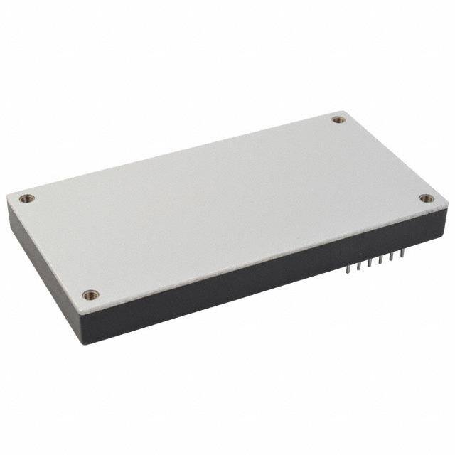
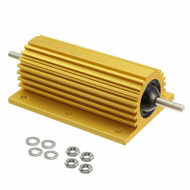
| 描述 | DC/DC CONVERTER 12V 50A |
| 产品分类 | DC DC Converters |
| 品牌 | CUI Inc |
| 数据手册 | |
| 产品图片 |
|
| 产品型号 | VFB600-D48-S12 |
| rohs | 无铅 / 符合限制有害物质指令(RoHS)规范要求 |
| RoHS指令信息 | http://www.cui.com/product/resource/digikeyrohs/vfb600-series |
| 产品系列 | VFB600 |
| 产品培训模块 | http://www.digikey.cn/PTM/IndividualPTM.page?site=cn&lang=zhs&ptm=30294http://www.digikey.cn/PTM/IndividualPTM.page?site=cn&lang=zhs&ptm=30387http://www.digikey.cn/PTM/IndividualPTM.page?site=cn&lang=zhs&ptm=30568 |
| 其它名称 | 102-2471 |
| 功率(W)-制造系列 | 600W |
| 功率(W)-最大值 | 600W |
| 包装 | 散装 |
| 大小/尺寸 | 4.60" 长 x 2.40" 宽 x 0.50" 高(116.8mm x 61.0mm x 12.7mm) |
| 安装类型 | 通孔 |
| 封装/外壳 | 整砖 |
| 工作温度 | -40°C ~ 100°C |
| 效率 | 90% |
| 标准包装 | 18 |
| 特性 | 远程开/关,OCP,OTP,OVP,SCP,UVLO |
| 电压-输入(最大值) | 75V |
| 电压-输入(最小值) | 36V |
| 电压-输出1 | 12V |
| 电压-输出2 | - |
| 电压-输出3 | - |
| 电压-隔离 | 1.5kV(1500V) |
| 电流-输出(最大值) | 50A |
| 相关产品 | /product-detail/zh/ATS-1148-C1-R0/ATS1510-ND/4146468/product-detail/zh/ATS-1149-C1-R0/ATS1511-ND/4146469/product-detail/zh/ATS-1151-C1-R0/ATS1490-ND/4146470/product-detail/zh/ATS-1108-C1-R0/ATS1507-ND/4146489/product-detail/zh/ATS-1109-C1-R0/ATS1508-ND/4146490/product-detail/zh/ATS-1111-C1-R0/ATS1509-ND/4146491 |
| 类型 | 隔离模块 |
| 视频文件 | http://www.digikey.cn/classic/video.aspx?PlayerID=1364138032001&width=640&height=505&videoID=2350204226001 |
| 输出数 | 1 |


- 商务部:美国ITC正式对集成电路等产品启动337调查
- 曝三星4nm工艺存在良率问题 高通将骁龙8 Gen1或转产台积电
- 太阳诱电将投资9.5亿元在常州建新厂生产MLCC 预计2023年完工
- 英特尔发布欧洲新工厂建设计划 深化IDM 2.0 战略
- 台积电先进制程称霸业界 有大客户加持明年业绩稳了
- 达到5530亿美元!SIA预计今年全球半导体销售额将创下新高
- 英特尔拟将自动驾驶子公司Mobileye上市 估值或超500亿美元
- 三星加码芯片和SET,合并消费电子和移动部门,撤换高东真等 CEO
- 三星电子宣布重大人事变动 还合并消费电子和移动部门
- 海关总署:前11个月进口集成电路产品价值2.52万亿元 增长14.8%

PDF Datasheet 数据手册内容提取
Additional Resources: Product Page | 3D Model | PCB Footprint date 04/10/2017 page 1 of 12 SERIES: VFB600 │ DESCRIPTION: DC-DC CONVERTER FEATURES • up to 700 W isolated output • industry standard full brick package • 2:1 input range (18~36 Vdc, 36~75 Vdc) • single output from 12~48 Vdc • 1,500 Vdc isolation • over current, over temperature, over voltage, and short circuit protections • remote on/off • efficiency up to 92% MODEL input output output output ripple efficiency voltage voltage current power and noise1 typ range max max max typ (Vdc) (Vdc) (Vdc) (A) (W) (mVp-p) (%) VFB600-D24-S12 24 18~36 12 50 600 120 88 VFB600-D24-S24 24 18~36 24 25 600 240 90 VFB600-D24-S28 24 18~36 28 21.5 600 280 90 VFB600-D24-S32 24 18~36 32 19 600 320 91 VFB600-D24-S48 24 18~36 48 12.5 600 480 91 VFB600-D48-S12 48 36~75 12 50 600 120 90 VFB600-D48-S24 48 36~75 24 25 600 240 92 VFB600-D48-S28 48 36~75 28 25 700 280 91 VFB600-D48-S32 48 36~75 32 19 600 320 92 VFB600-D48-S48 48 36~75 48 12.5 600 480 92 Notes: 1. Ripple and noise measured at full load, 20 MHz BW with 10 μF tantalum and 1 μF ceramic capacitor across the output. 2. An external input capacitor of 220 μF is recommended to reduce input ripple voltage. 3. All specifications measured at nominal line, full load, and 25°C unless otherwise specified. PART NUMBER KEY VFB600 - DXX - SXX X Base Number Remote On/Off Control Input Voltage Output Voltage "blank" = positive logic N = negative logic cui.com
Additional Resources: Product Page | 3D Model | PCB Footprint CUI Inc │ SERIES: VFB600 │ DESCRIPTION: DC-DC CONVERTER date 04/10/2017 │ page 2 of 12 INPUT parameter conditions/description min typ max units 24 Vdc input models 18 24 36 Vdc operating input voltage 48 Vdc input models 36 48 75 Vdc power up 17 Vdc 24 Vdc input power down 16 Vdc under voltage shutdown power up 35 Vdc 48 Vdc input power down 33 Vdc power up 38 Vdc 24 Vdc input power down 40 Vdc over voltage shutdown power up 77 Vdc 48 Vdc input power down 80 Vdc start-up time 250 ms models ON (0~0.01 mA) positive logic models OFF (1.0~10 mA) on/off1 models ON (1.0~10 mA) negative logic models OFF (0~0.01 mA) filter pi filter 60 A time delay fuse for 24 Vin models, input fuse 30 A time delay fuse for 48 Vin models Note: 1. See application notes. OUTPUT parameter conditions/description min typ max units 12 Vdc output models 470 10,000 μF output capacitance2 all other models 470 5,000 μF line regulation2 from low line to high line ±0.2 % load regulation2 from full load to no load ±0.5 % voltage accuracy2 ±1.5 % load share accuracy from 50~100% load ±10 % adjustability 60 110 % 48 Vdc input: 12 Vdc, 28 Vdc, 32 Vdc models 300 kHz switching frequency all other models 250 kHz transient response 25% load step change 500 μs temperature coefficient ±0.03 %/°C Vout ready: low level, sink current 20 mA power good (IOC) Vout not ready: open drain output, applied voltage 50 V auxiliary output voltage/current 10 ±3 Vdc, 20 mA max. Note: 2. Minimum capacitor values are required on the output to maintain the specified regulation. PROTECTIONS parameter conditions/description min typ max units short circuit protection continuous over current protection 110 150 % over voltage protection 115 140 % over temperature protection shutdown 110 °C cui.com
Additional Resources: Product Page | 3D Model | PCB Footprint CUI Inc │ SERIES: VFB600 │ DESCRIPTION: DC-DC CONVERTER date 04/10/2017 │ page 3 of 12 SAFETY AND COMPLIANCE parameter conditions/description min typ max units for 1 minute, input to output, input to case, or isolation voltage 1,500 Vdc output to case isolation resistance 10 MΩ isolation capacitance 4,000 pF safety approvals UL 60950-1 MTBF as per MIL-HDBK-217F at full load, GB, 25 °C 450,000 hours RoHS 2011/65/EU (CE) ENVIRONMENTAL parameter conditions/description min typ max units operating case temperature see derating curve -40 100 °C storage temperature -55 105 °C humidity non-condensing 95 % SOLDERABILITY parameter conditions/description min typ max units wave soldering see wave soldering profile 260 °C 300 C)250 ° Notes: 1. Soldering materials: Sn/Cu/Ni e (200 2. Ramp up rate during preheat: 1.4°C/s (from 50°C to 100°C) ur 3. Soaking temperature: 0.5°C/s (from 100°C to 130°C), 60±20 seconds at150 45.. PReaamkp t edmowpner raattuer ed:u 2ri6n0g° cCo, oalibnogv:e - 1205°0C°C/s f(ofrr o3m~ 62 6se0c°oCn tdos 150°C) mper100 Te 50 0 0 20 40 60 80 100 120 140 160 180 MECHANICAL Time (Seconds) parameter conditions/description min typ max units dimensions 116.8 x 61.0 x 12.7(4.60 x 2.40 x 0.50 inch) mm case material aluminum baseplate with plastic case weight 220 g cui.com
Additional Resources: Product Page | 3D Model | PCB Footprint CUI Inc │ SERIES: VFB600 │ DESCRIPTION: DC-DC CONVERTER date 04/10/2017 │ page 4 of 12 MECHANICAL DRAWING units: mm[inch] tolerance: X.X = ±0.5[±0.02] X.XX = ±0.25[±0.010] pin diameter tolerance: ±0.1[±0.004] 104.114.099 100.303.949 96.493.799 92.683.649 88.873.499 1.020.040 PIN CONNECTIONS 3.500.138 85.063.349 (8 PLCS) THROUGH HOLE Pin Function (4 PLCS) 161514131211 1 -Vin 2.060.081 10 (8 PLCS) 2 +Vin 1 9 57.172.251 3 -ON/OFF 43.201.701 8 35.561.400 4 +ON/OFF 2 10.160.400 61.002.402 22.860.900 33.041.301 7 5 +Vo 3 50.802.000 4 6 6 +Vo 22.880.901 5 7 +Vo 19.070.751 8 -Vo 9 -Vo 5.050.199 106.704.201 10 -Vo 11 -S 7.200.283 (TYP) 12 +S 13 TRIM 12.700.500 14 PC/NC 15 IOC 116.804.598 16 AUX 2.4mm PLATED THROUGH HOLE 4.8mm PAD SIZE 3.5mm NON THROUGH HOLE 1.4mm PLATED THROUGH HOLE 2.8mm PAD SIZE PCB Layout Top View cui.com
Additional Resources: Product Page | 3D Model | PCB Footprint CUI Inc │ SERIES: VFB600 │ DESCRIPTION: DC-DC CONVERTER date 04/10/2017 │ page 5 of 12 DERATING CURVES VFB600-D24-S12 Derating Curves VFB600-D24-S24 Derating Curves 110 110 100 100 Natural Convention Natural Convention 90 20 ft./min (0.1 m/s) 90 20 ft./min (0.1 m/s) 80 400 ft./min (2.0 m/s) 80 400 ft./min (2.0 m/s) %)70 800 ft./min (4.0 m/s) %)70 800 ft./min (4.0 m/s) d (60 d (60 a50 a50 o o L L 40 40 30 30 20 20 10 10 0 0 -40 -30 -20 -10 0 10 20 30 40 50 60 70 80 90 100 -40 -30 -20 -10 0 10 20 30 40 50 60 70 80 90 100 Ambient Temperature (°C) Ambient Temperature (°C) VFB600-D24-S28 Derating Curves VFB600-D24-S32 Derating Curves 110 110 100 100 Natural Convention Natural Convention 90 20 ft./min (0.1 m/s) 90 20 ft./min (0.1 m/s) 80 400 ft./min (2.0 m/s) 80 400 ft./min (2.0 m/s) %)70 800 ft./min (4.0 m/s) %)70 800 ft./min (4.0 m/s) d (60 d (60 a50 a50 o o L L 40 40 30 30 20 20 10 10 0 0 -40 -30 -20 -10 0 10 20 30 40 50 60 70 80 90 100 -40 -30 -20 -10 0 10 20 30 40 50 60 70 80 90 100 Ambient Temperature (°C) Ambient Temperature (°C) VFB600-D24-S48 Derating Curves 110 100 Natural Convention 90 20 ft./min (0.1 m/s) 80 400 ft./min (2.0 m/s) 70 800 ft./min (4.0 m/s) %)60 d ( a50 o L40 30 20 10 0 -40 -30 -20 -10 0 10 20 30 40 50 60 70 80 90 100 Ambient Temperature (°C) cui.com
Additional Resources: Product Page | 3D Model | PCB Footprint CUI Inc │ SERIES: VFB600 │ DESCRIPTION: DC-DC CONVERTER date 04/10/2017 │ page 6 of 12 DERATING CURVES (CONTINUED) VFB600-D48-S12 Derating Curves VFB600-D48-S24 Derating Curves 110 110 100 100 Natural Convention 90 20 ft./min (0.1 m/s) 90 80 400 ft./min (2.0 m/s) 80 70 800 ft./min (4.0 m/s) 70 %) %) d (60 d (60 a50 a50 o o L40 L40 Natural Convention 30 30 20 ft./min (0.1 m/s) 20 20 400 ft./min (2.0 m/s) 10 10 800 ft./min (4.0 m/s) 0 0 -40 -30 -20 -10 0 10 20 30 40 50 60 70 80 90 100 -40 -30 -20 -10 0 10 20 30 40 50 60 70 80 90 100 Ambient Temperature (°C) Ambient Temperature (°C) VFB600-D48-S28 Derating Curves VFB600-D48-S32 Derating Curves 110 110 100 100 Natural Convention 90 20 ft./min (0.1 m/s) 90 80 400 ft./min (2.0 m/s) 80 70 800 ft./min (4.0 m/s) 70 %) %) d ( 60 d (60 a 50 a50 o o L 40 L40 Natural Convention 30 30 20 ft./min (0.1 m/s) 20 20 400 ft./min (2.0 m/s) 10 10 800 ft./min (4.0 m/s) 0 0 -40 -30 -20 -10 0 10 20 30 40 50 60 70 80 90 100 -40 -30 -20 -10 0 10 20 30 40 50 60 70 80 90 100 Ambient Temperature (°C) Ambient Temperature (°C) VFB600-D48-S48 Derating Curves 110 100 90 80 70 %) 60 d( oa50 L 40 Natural Convention 30 20 ft./min (0.1 m/s) 20 400 ft./min (2.0 m/s) 10 800 ft./min (4.0 m/s) 0 -40 -30 -20 -10 0 10 20 30 40 50 60 70 80 90 100 Ambient Temperature (°C) cui.com
Additional Resources: Product Page | 3D Model | PCB Footprint CUI Inc │ SERIES: VFB600 │ DESCRIPTION: DC-DC CONVERTER date 04/10/2017 │ page 7 of 12 EFFICIENCY CURVES VFB600-D24-S12 Efficiency Curve VFB600-D24-S24 Efficiency Curve (Efficiency vs. Line Voltage and Load Current) (Efficiency vs. Line Voltage and Load Current) 95 95 90 90 85 85 %) %) y (80 y (80 c c en75 18 Vdc en75 Effici70 24 Vdc Effici70 1284 VVddcc 36 Vdc 65 65 36 Vdc 60 60 10 20 30 40 50 60 70 80 90 100 10 20 30 40 50 60 70 80 90 100 Load Current (%) Load Current (%) VFB600-D24-S28 Efficiency Curve VFB600-D24-S32 Efficiency Curve (Efficiency vs. Line Voltage and Load Current) (Efficiency vs. Line Voltage and Load Current) 95 95 90 90 85 85 %) %) y (80 y (80 c c en75 18 Vdc en75 18 Vdc ci ci Effi70 24 Vdc Effi70 24 Vdc 36 Vdc 36 Vdc 65 65 60 60 10 20 30 40 50 60 70 80 90 100 10 20 30 40 50 60 70 80 90 100 Load Current (%) Load Current (%) VFB600-D24-S48 Efficiency Curve (Efficiency vs. Line Voltage and Load Current) 95 90 85 ) % (80 y c n e75 18 Vdc ci Effi70 24 Vdc 36 Vdc 65 60 10 20 30 40 50 60 70 80 90 100 Load Current (%) cui.com
Additional Resources: Product Page | 3D Model | PCB Footprint CUI Inc │ SERIES: VFB600 │ DESCRIPTION: DC-DC CONVERTER date 04/10/2017 │ page 8 of 12 EFFICIENCY CURVES (CONTINUED) VFB600-D48-S12 Efficiency Curve VFB600-D48-S24 Efficiency Curve (Efficiency vs. Line Voltage and Load Current) (Efficiency vs. Line Voltage and Load Current) 95 95 90 90 85 85 ) ) % % ( y (80 cy 80 Efficienc7705 3468 VVddcc Efficien7705 3468 VVddcc 75 Vdc 75 Vdc 65 65 60 60 10 20 30 40 50 60 70 80 90 100 10 20 30 40 50 60 70 80 90 100 Load Current (%) Load Current (%) VFB600-D48-S28 Efficiency Curve VFB600-D48-S32 Efficiency Curve (Efficiency vs. Line Voltage and Load Current) (Efficiency vs. Line Voltage and Load Current) 95 95 90 90 85 85 ) % ) % cy (80 y (80 Efficien7705 3468 VVddcc Efficienc7705 3468 VVddcc 75 Vdc 75 Vdc 65 65 60 60 10 20 30 40 50 60 70 80 90 100 10 20 30 40 50 60 70 80 90 100 Load Current (%) Load Current (%) VFB600-D48-S48 Efficiency Curve (Efficiency vs. Line Voltage and Load Current) 95 90 85 ) % (80 y c n e75 ci 36 Vdc Effi70 48 Vdc 65 75 Vdc 60 10 20 30 40 50 60 70 80 90 100 Load Current (%) cui.com
Additional Resources: Product Page | 3D Model | PCB Footprint CUI Inc │ SERIES: VFB600 │ DESCRIPTION: DC-DC CONVERTER date 04/10/2017 │ page 9 of 12 APPLICATION NOTES 1. Parallel Operation The VFB600 series is designed for parallel operation. When in parallel the load current can be shared equally between the two modules by connecting their PC pins. The VFB600 can be setup in two different modes to achieve parallel operation. The standard parallel operation is suitable when load cannot be handled by a single unit, whereas the N+1 redundant operation is suitable for loads when backup power is required. Figure 1 Figure 2 Standard Parallel Connection Parallel Connection With Programmed And Adjustable Output +S +S +V +V -V -V -S -S L L TRIM O PC O PC A A D D +S +S +V +V -V -V -S -S TRIM PC PC Figure 3 Figure 4 N+1 Redundant Connection N+1 Redundant Connection With Programmed Output And Adjustable Output Voltage +S +S +V +V -V -V -S -S L L PC O TRIM O A PC A D +S D +V +S +V -V -S -V -S PC TRIM PC cui.com
Additional Resources: Product Page | 3D Model | PCB Footprint CUI Inc │ SERIES: VFB600 │ DESCRIPTION: DC-DC CONVERTER date 04/10/2017 │ page 10 of 12 APPLICATION NOTES (CONTINUED) 2. Output Voltage Trimming Leave open if not used. Figure 5 Trim-Up/Trim-Down Formulas External Resistors +S Rt×33 1.24×( ) VR Rt+33 Vf = +V Rt×33 7.68+( ) Rt+33 -V Vout=(Vo+VR)×Vf -S Note: Rt = 6.8 kΩ V is the nominal output voltage O V is the desired output voltage (up or down) OUT VR is the trim resistor in kΩ Figure 6 External DC Voltage Trim-Up/Trim-Down Formula Vout =VT×VO Note: V is the trim terminal voltage T V is the nominal output voltage O V is the desired output voltage (up or down) OUT 3. ON/OFF Control The converter's ON/OFF function can be controlled from the input side or from the output side. The maximum current through the ON/OFF pin is 10 mA. The resistor value has to be set appropriately to avoid the maximum current through the ON/OFF pins. The remote on/off control has to be connected for the converter to operate. (A) Controlling the ON/OFF terminal from the input side. (B) Controlling the ON/OFF terminal from the output Recommended R1 value is 30 kΩ (0.5 W) for 48V and side. Recommended R2 value is 5.1 kΩ (0.1 W) IN 15 kΩ (0.25 W) for 24V IN Figure 7 Figure 8 AUX R2 Output -S 1k SW +ON/OFF I(ON/OFF) -ON/OFF cui.com
Additional Resources: Product Page | 3D Model | PCB Footprint CUI Inc │ SERIES: VFB600 │ DESCRIPTION: DC-DC CONVERTER date 04/10/2017 │ page 11 of 12 APPLICATION NOTES (CONTINUED) 4. IOC Signal Normal and abnormal operation of the converter can be monitored by using the I.O.C signal. Output of this signal monitor is located at the secondary side and is open collector output, you can use the signal by the internal aux power supply or the the external DC supply as the following figures. the ground reference is the –Sense. This signal is LOW when the converter is normally operating and HIGH when the converter is disabled or when the converter is abnormally operating. Figure 9 Figure 10 Internal AUX Power External DC Power AUX AUX DC IOC IOC -S -S 5. Output Remote Sensing This series has the capability to remotely sense both lines of its output. This feature moves the effective output voltage regulation point from the output of the unit to the point of connection of the remote sense pins. This feature automatically adjusts the real output voltage in order to compensate for voltage drops in distribution and maintain a regulated voltage at the point of load. The voltage range of this is: [(+Vout) – (-Vout)] – [(+Sense) – (-Sense)] ≤ 10% of the Vout nominal. If the sense feature is not used, the sense pins should be connected locally to the respective Vout pins. Please note that although the output voltage can be increased by both the remote sense and by the trim, the maximum increase for the output voltage is not the sum of both. Figure 11 6. Test Configuration Figure 12 Table 1 A +Vin +Vout Recommended External components +S C1 220 μF/100 V R1 A V +ON/OFF TRIM C2 C2 470 μF/100 V C1 DC -ON/OFF Load -S -Vin -Vout cui.com
Additional Resources: Product Page | 3D Model | PCB Footprint CUI Inc │ SERIES: VFB600 │ DESCRIPTION: DC-DC CONVERTER date 04/10/2017 │ page 12 of 12 REVISION HISTORY rev. description date 1.0 initial release 06/27/2011 1.02 adjustability note added, V-Infinity branding removed 08/07/2012 1.03 updated spec 04/01/2013 1.04 added UL approvals to 24 Vdc and 48 Vdc output models 03/05/2014 1.05 added application note information 04/10/2017 The revision history provided is for informational purposes only and is believed to be accurate. Headquarters 20050 SW 112th Ave. Fax 503.612.2383 Tualatin, OR 97062 cui.com 800.275.4899 techsupport@cui.com CUI offers a two (2) year limited warranty. Complete warranty information is listed on our website. CUI reserves the right to make changes to the product at any time without notice. Information provided by CUI is believed to be accurate and reliable. However, no responsibility is assumed by CUI for its use, nor for any infringements of patents or other rights of third parties which may result from its use. CUI products are not authorized or warranted for use as critical components in equipment that requires an extremely high level of reliability. A critical component is any component of a life support device or system whose failure to perform can be reasonably expected to cause the failure of the life support device or system, or to affect its safety or effectiveness.