ICGOO在线商城 > 电路保护 > TVS - 变阻器,MOV > V25S115P
 Datasheet下载
- 型号: V25S115P
- 制造商: Littelfuse
- 库位|库存: xxxx|xxxx
- 要求:
| 数量阶梯 | 香港交货 | 国内含税 |
| +xxxx | $xxxx | ¥xxxx |
查看当月历史价格
查看今年历史价格
V25S115P产品简介:
ICGOO电子元器件商城为您提供V25S115P由Littelfuse设计生产,在icgoo商城现货销售,并且可以通过原厂、代理商等渠道进行代购。 V25S115P价格参考。LittelfuseV25S115P封装/规格:TVS - 变阻器,MOV, 180V 22kA Varistor 1 Circuit Through Hole Radial。您可以下载V25S115P参考资料、Datasheet数据手册功能说明书,资料中有V25S115P 详细功能的应用电路图电压和使用方法及教程。
型号为V25S115P的Littelfuse Inc.产品属于TVS(瞬态电压抑制)变阻器,具体为MOV(金属氧化物压敏电阻)类型。该器件主要用于电路中保护电子元件免受瞬态电压(如雷击浪涌、静电放电或开关噪声)的损害。

应用场景包括:

1. 工业控制系统:用于保护PLC、传感器、执行器等关键部件免受工业环境中常见的电压浪涌影响。

2. 通信设备:在基站、路由器、交换机等通信设备中,用于保护电源及信号线路免受雷击或静电干扰。

3. 电源供应器:广泛应用于开关电源、UPS(不间断电源)中,作为初级或次级电路的浪涌保护元件。

4. 消费电子产品:如电视、空调、洗衣机等家电中,用于提升设备的电磁兼容性和可靠性。

5. 安防系统:用于监控摄像头、门禁系统等安防设备中,确保其在恶劣环境下的稳定运行。

6. 智能电表与能源管理系统:保护计量模块免受电网浪涌影响,提高系统长期运行的稳定性。

V25S115P具备较高的浪涌吸收能力与响应速度,适用于交流和直流电路中,是中高功率电路中常用的保护元件。
| 参数 | 数值 |
| 产品目录 | |
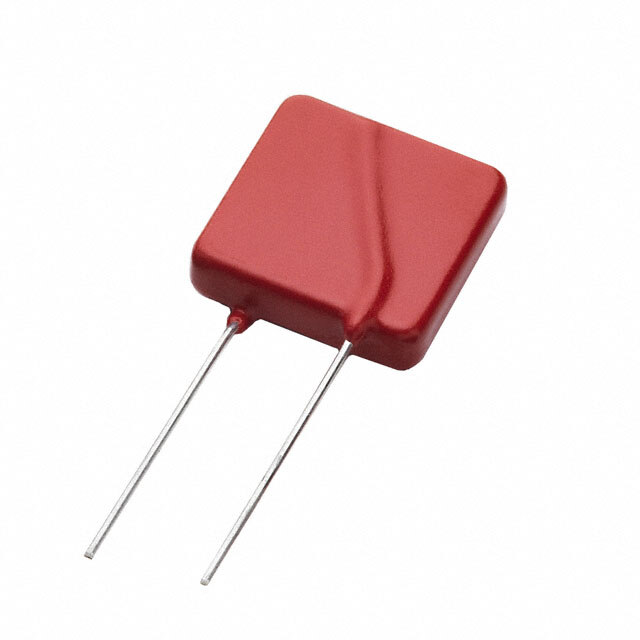
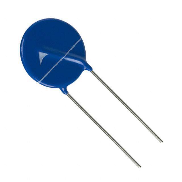
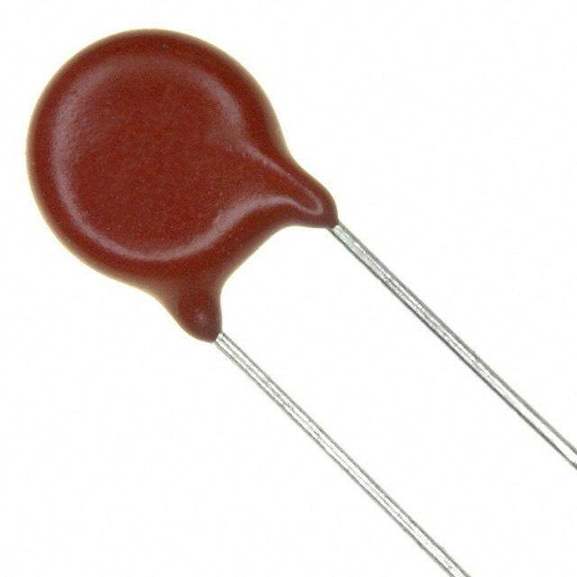
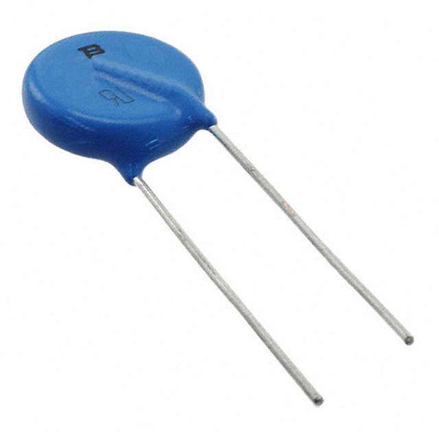
| 描述 | VARISTOR 162V 22KA DISC RADIAL压敏电阻 115VAC 230J 295V CLAMP 22KAPK 25MM |
| 产品分类 | |
| 品牌 | Littelfuse |
| 产品手册 | |
| 产品图片 |
|
| rohs | 符合RoHS无铅 / 符合限制有害物质指令(RoHS)规范要求 |
| 产品系列 | Littelfuse V25S115PUltraMOV™ 25S |
| 数据手册 | |
| 产品型号 | V25S115P |
| 产品 | MOV |
| 产品培训模块 | http://www.digikey.cn/PTM/IndividualPTM.page?site=cn&lang=zhs&ptm=25936 |
| 产品种类 | 压敏电阻 |
| 其它名称 | F5385 |
| 包装 | 散装 |
| 变阻器电压 | 162V |
| 商标 | Littelfuse |
| 外壳宽度 | 28 mm |
| 外壳直径 | 25 mm |
| 安装 | Radial |
| 容差 | 5 % |
| 封装 | Bulk |
| 封装/外壳 | 径向 |
| 尺寸 | 25 mm Dia. x 28 mm W x 32.5 mm L |
| 峰值浪涌电流 | 22 kA |
| 工作温度范围 | - 55 C to + 85 C |
| 工厂包装数量 | 80 |
| 最大AC电压 | 115VAC |
| 最大DC电压 | 150VDC |
| 标准包装 | 80 |
| 浪涌能量额定值 | 230 J |
| 电压额定值AC | 115 V |
| 电压额定值DC | 150 V |
| 电容 | 4500 pF |
| 电流-浪涌 | 22kA |
| 电路数 | 1 |
| 直径 | 25 mm |
| 系列 | 25S |
| 能量 | 230J |
| 钳位电压 | 295 V |


- 商务部:美国ITC正式对集成电路等产品启动337调查
- 曝三星4nm工艺存在良率问题 高通将骁龙8 Gen1或转产台积电
- 太阳诱电将投资9.5亿元在常州建新厂生产MLCC 预计2023年完工
- 英特尔发布欧洲新工厂建设计划 深化IDM 2.0 战略
- 台积电先进制程称霸业界 有大客户加持明年业绩稳了
- 达到5530亿美元!SIA预计今年全球半导体销售额将创下新高
- 英特尔拟将自动驾驶子公司Mobileye上市 估值或超500亿美元
- 三星加码芯片和SET,合并消费电子和移动部门,撤换高东真等 CEO
- 三星电子宣布重大人事变动 还合并消费电子和移动部门
- 海关总署:前11个月进口集成电路产品价值2.52万亿元 增长14.8%

PDF Datasheet 数据手册内容提取
Metal-Oxide Varistors (MOVs) Radial Lead Varistors > UltraMOVTM 25S Varistor Series UltraMOV® 25S Varistor Series RoHS Description The UltraMOV® 25S Varistor Series is designed for applications requiring high peak surge current ratings and high energy absorption capability. UltraMOV™ varistors are primarily intended for use in AC Line Voltage applications such as Surge Protective Devices (SPD), Uninterruptable Power Supplies (UPS), AC Power Taps, AC Power Meters, or other products that require voltage clamping of high transient surge currents from sources such as lightning, inductive load switching, or capacitor bank switching. These devices have 25mm square forms are produced in a radial lead package and offered with straight leads. Agency Approvals UltraMOV® 25S varistors are manufactured with recognized epoxy encapsulation and are rated for ambient Agency Agency Approval Agency File Number temperatures up to 85°C with no derating. This 25S Series is LASER-branded and is supplied in bulk packaging. UL1449 E320116 22.2-1 091788 Features IEC 61051-1, IEC61051-2, IEC 60950-1 (Annex Q) 116895 • Lead–free and • Custom voltage RoHS compliant. types available Additional Information • High peak surge • Standard lead form current rating (I ) and lead space options TM 22kA, single 8/20µs pulse, (25mm) • Standard operating Datasheet Resources Samples voltage range compatible with common AC line voltages (115 to 750VAC) Absolute Maximum Ratings • For ratings of individual members of a series, see Device Ratings and Specifications chart Continuous UltraMOV® 25S Varistor Series Units Steady State Applied Voltage: AC Voltage Range (V ) 115 to 750 V M(AC)RMS DC Voltage Range (V ) 150 to 970 V M(DC) Transients: Peak Pulse Current (I ) 8x20µs Current Wave Single Pulse 22,000 A TM Single-Pulse Energy Capability (W ) 2ms Current Wave 230 to 890 J TM Operating Ambient Temperature Range (T) -55 to +85 ºC A Storage Temperature Range (T ) -55 to +125 ºC STG Temperature Coefficient (aV) of Clamping Voltage (V) at Specified Test Current <0.01 %/C C Hi-Pot Encapsulation (COATING Isolation Voltage Capability) 2500 V Dielectic Withstand DC for 1 min per MIL–STD–202, Method 301 Insulation Resistance of the Epoxy Coating 1000 MΩ CAUTION: Stresses above those listed in "Absolute Maximum Ratings" may cause permanent damage to the device. This is a stress only rating and operation of the device at these or any other conditions above those indicated in the operational sections of this specification is not implied. © 2018 Littelfuse, Inc. Specifications are subject to change without notice. Revised: 11/01/18
Metal-Oxide Varistors (MOVs) Radial Lead Varistors > UltraMOVTM 25S Varistor Series Ratings & Specifications Maximum Rating (85°C) Specifications (25°C) Continuous Transient Maximum UL 1449 Typical Varistor Voltage Peak Surge Clamping Voltage Capaci- Energy at 1mA DC AC Volts DC Volts Current Voltage at 100A, Protection tance Part Branding 2ms 8 x 20µs Test Current 8 x 20µs Rating f = 1MHz Number W TM I V V V V 1 x TM NOM NOM V VPR C M(AC)RMS M(DC) 1 x Pulse Min Max C Pulse (V) (V) (J) (A) (V) (V) (pF) V25S115P P25S115 115 150 230 22000 162 198 295 400 4500 V25S130P P25S130 130 170 255 22000 184.5 225.5 335 500 3900 V25S140P P25S140 140 180 285 22000 198 242 355 500 3500 V25S150P P25S150 150 200 300 22000 216 264 390 500 3200 V25S175P P25S175 175 225 315 22000 243 297 450 600 2550 V25S230P P25S230 230 300 400 22000 324 396 585 700 1900 V25S250P P25S250 250 320 435 22000 351 429 640 800 1750 V25S275P P25S275 275 350 470 22000 387 473 700 900 1610 V25S300P P25S300 300 385 500 22000 423 517 765 1000 1450 V25S320P P25S320 320 420 540 22000 459 561 825 1000 1350 V25S385P P25S385 385 505 630 22000 558 682 1010 1200 1080 V25S420P P25S420 420 560 655 22000 612 748 1100 1500 1000 V25S440P P25S440 440 585 675 22000 643.5 786.5 1160 n/a 900 V25S460P P25S460 460 615 690 22000 675 825 1220 n/a 870 V25S510P P25S510 510 670 700 22000 738 902 1335 n/a 820 V25S550P P25S550 550 745 765 22000 819 1001 1475 n/a 750 V25S625P P25S625 625 825 800 22000 900 1100 1625 n/a 660 V25S750P P25S750 750 970 890 22000 1080 1320 1950 n/a 550 Note: Average powder dissipation of transients should not exceed 1.5 watts. Transient V-I Characteristics Curves Peak Current, Energy and Power Derating Curve Peak Pulse Current Test Waveform for Clamping Voltage 100 100 UE UE L L D VA 80 AK VA ATE 60 OF PE 50 F R NT O E T 40 RC N PE E C R 20 PE 0 t TIME 0 Figure O21 t1 t2 55 50 60 70 80 90 100 110 120 130 Figure 1 AMBIENT TEMPERATURE (ºC) 0 = Virtual Origin of Wave 1 T = Time from 10% to 90% of Peak T = Rise Time = 1.25 x T 1 For applications exceeding 85ºC ambient temperature, the T = Decay Time 2 peak surge current and energy ratings must be reduced as Example - For an 8/20 µs Current Waveform: shown above. 8µs = T = Rise Time 1 20µs = T = Decay Time 2 © 2018 Littelfuse, Inc. Specifications are subject to change without notice. Revised: 11/01/18
Metal-Oxide Varistors (MOVs) Radial Lead Varistors > UltraMOVTM 25S Varistor Series Transient V-I Characteristic Curve 10000 750 625 550 age (V) 385 420 440 460 510 olt V k a e 1000 P m u m xi a M 320 300 275 250 150 175 230 140 130 115 100 0.00001 0.0001 0.001 0.01 0.1 1 10 100 1000 10000 100000 Figure 3 Peak Current (A) Pulse Rating Curve 100000 1 2 10000 15 102 103 A) 1000 nt ( 104 Curre 110056 k a Pe 100 ∞ 10 1 10 100 1000 10000 Figure 4 Impulse Duration (µs) Note: Repetitive surge capability is qualified and tested based on 8/20us current waveform (not combination waveform) and UL1449 40.7.3 (Edition 4) test condition. © 2018 Littelfuse, Inc. Specifications are subject to change without notice. Revised: 11/01/18
Metal-Oxide Varistors (MOVs) Radial Lead Varistors > UltraMOVTM 25S Varistor Series Wave Solder Profile Non Lead–free Wave Solder Profile Lead–free Wave Solder Profile 300 300 Maximum Wave 260C Maximum Wave 240C 250 250 C) C) E (º 200 E (º 200 R R U U T T A 150 A 150 R R E E P P M 100 M 100 E E T T 50 50 0 0 0 0.5 1 1.5 2 2.5 3 3.5 4 0 0.5 1 1.5 2 2.5 3 3.5 4 Figure 5 TIME(MINUTES) Figure 6 TIME(MINUTES) Physical Specifications Environmental Specifications Lead Material Copper Clad Steel Wire -55°C to +85°C Operating Temperature Soldering Solderability per MIL–STD–202, Characteristics Method 208 Storage Temperature -55°C to +125°C Cured, flame retardant epoxy polymer Insulating Material meets UL94V–0 requirements Humidity Aging +85°C, 85% RH, 1000 hours +/-10% typical voltage change Marked with LF, voltage, UL/CSA Logos, Device Labeling and date code +85°C to -40°C 5 times Thermal Shock +/-10% typical voltage change Solvent Resistance MIL–STD–202, Method 215 Moisture Sensitivity Level 1, J-STD-020 UltraMOV® 25S Varistor Series for High-Temperature Operating Conditions: Phenolic coated devices are available with improved maximum operating temperature 125ºC. These devices also have improved temperature cycling capability. Ratings and specifications are per standard series except Hi–Pot Encapsulation (Isolation Voltage Capability) = 500V. To order: add 'X1347' to part number (e.g. V25S150PX1347). These devices are NOT UL, CSA, CECC or VDE certified.Contact factory for further details. © 2018 Littelfuse, Inc. Specifications are subject to change without notice. Revised: 11/01/18
Metal-Oxide Varistors (MOVs) Radial Lead Varistors > UltraMOVTM 25S Varistor Series Product Dimensions (mm) D A b b D e e e1 e1 E L max min max max min max min max max min V25S115P 1.5 2.7 5.7 V25S130P 1.6 2.9 5.9 V25S140P 1.7 3.0 6.0 A V25S150P 1.8 3.1 6.1 V25S175P 1.9 3.3 6.3 V25S230P 2.0 3.4 6.4 V25S250P 2.1 3.5 6.5 L V25S275P 2.3 3.7 6.7 V25S300P 2.4 3.9 6.9 b 32.5 0.95 1.05 28 11.7 13.7 25.4 V25S320P 2.6 4.1 7.1 e V25S385P 3.0 4.7 7.7 V25S420P 3.3 5.0 8.0 1 E e V25S440P 3.4 5.2 8.2 V25S460P 3.6 5.4 8.4 V25S510P 1.6 3.4 8.7 V25S550P 1.9 3.9 9.2 V25S625P 2.3 4.3 9.6 V25S750P 3.1 5.4 10.7 Notes 1. Additional optional lead form, packaging and lead spacing requirements are subject to availability and to minimum order requirements. Please contact factory for details. 2. Nickel Barrier Wire option (Suffix 'X2855')Standard parts use Tin-Coated Copper wire. Nickel Barrier Coated Wire is available as an option. This is Copper Wire with a flashing of Nickel, followed by a top coat of Tin. To order please add suffix 'X2855' to end of standard part number. Contact factory for more details if required. Disclaimer Notice - Information furnished is believed to be accurate and reliable. However, users should independently evaluate the suitability of and test each product selected for their own applications. Littelfuse products are not designed for, and may not be used in, all applications. Read complete Disclaimer Notice at www.littelfuse.com/disclaimer-electronics. © 2018 Littelfuse, Inc. Specifications are subject to change without notice. Revised: 11/01/18