ICGOO在线商城 > 继电器 > 信号继电器,高达 2 A > V23026A1002B201
 Datasheet下载
- 型号: V23026A1002B201
- 制造商: CORCOM/TYCO ELECTRONICS
- 库位|库存: xxxx|xxxx
- 要求:
| 数量阶梯 | 香港交货 | 国内含税 |
| +xxxx | $xxxx | ¥xxxx |
查看当月历史价格
查看今年历史价格
V23026A1002B201产品简介:
ICGOO电子元器件商城为您提供V23026A1002B201由CORCOM/TYCO ELECTRONICS设计生产,在icgoo商城现货销售,并且可以通过原厂、代理商等渠道进行代购。 V23026A1002B201价格参考¥44.77-¥71.64。CORCOM/TYCO ELECTRONICSV23026A1002B201封装/规格:信号继电器,高达 2 A, 通用 继电器 SPDT(1 Form C) 通孔。您可以下载V23026A1002B201参考资料、Datasheet数据手册功能说明书,资料中有V23026A1002B201 详细功能的应用电路图电压和使用方法及教程。
TE Connectivity Potter & Brumfield Relays 的 V23026A1002B201 型号信号继电器,额定电流为 2 A,适用于多种工业和商业应用场景。该型号的继电器因其高可靠性和紧凑设计,在多个领域中具有广泛的应用潜力。

 工业自动化
在工业自动化系统中,V23026A1002B201 继电器可用于控制各种低功率设备的开关操作。例如,它可以用于PLC(可编程逻辑控制器)系统中,作为信号传输和控制的关键组件。该继电器能够承受频繁的开关操作,确保系统的稳定性和可靠性。此外,它还可以用于传感器、执行器和其他自动化设备之间的信号传递,帮助实现精确的控制和反馈。

 楼宇自动化
楼宇自动化系统中,V23026A1002B201 可用于照明控制、暖通空调(HVAC)系统以及安全监控系统。例如,在智能照明系统中,该继电器可以控制不同区域的灯光开关,根据时间或传感器信号自动调节亮度。在HVAC系统中,它可以用于控制风机、水泵等设备的启停,确保室内环境的舒适度。同时,该继电器也可用于门禁控制系统,实现对出入口的自动化管理。

 家用电器
在家用电器领域,V23026A1002B201 继电器可用于冰箱、洗衣机、空调等设备中。它可以在这些设备的电路板上起到关键的开关作用,例如控制压缩机、风扇电机等部件的启动和停止。由于其小巧的设计和稳定的性能,该继电器能够在有限的空间内提供可靠的电气连接,延长家电的使用寿命。

 通信设备
在通信设备中,V23026A1002B201 继电器可用于电源切换、信号隔离等场景。例如,在基站设备中,该继电器可以用于备用电源的自动切换,确保通信网络的不间断运行。此外,它还可以用于隔离不同电压等级的电路,防止信号干扰,提高通信质量。

总之,V23026A1002B201 继电器凭借其高性能和广泛应用性,成为众多行业中不可或缺的电子元件。
| 参数 | 数值 |
| 3D型号 | http://www.te.com/commerce/DocumentDelivery/DDEController?Action=srchrtrv&DocNm=1393774-8&DocType=Customer+View+Model&DocLang=English |
| 产品目录 | |
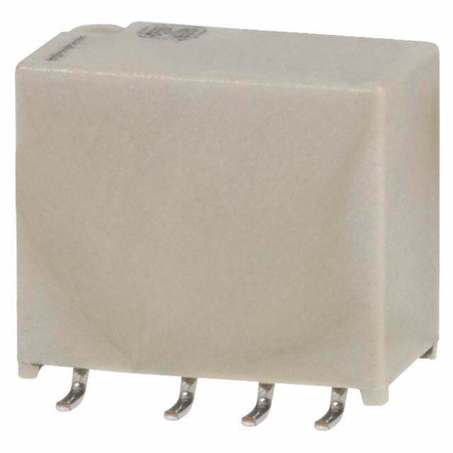
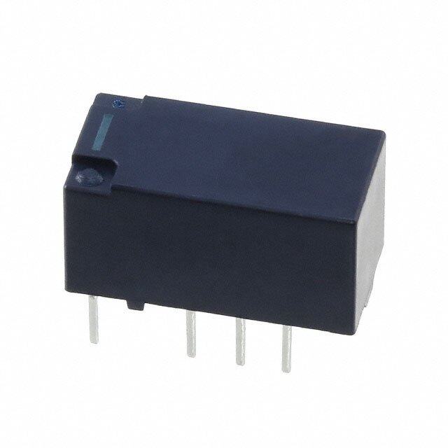
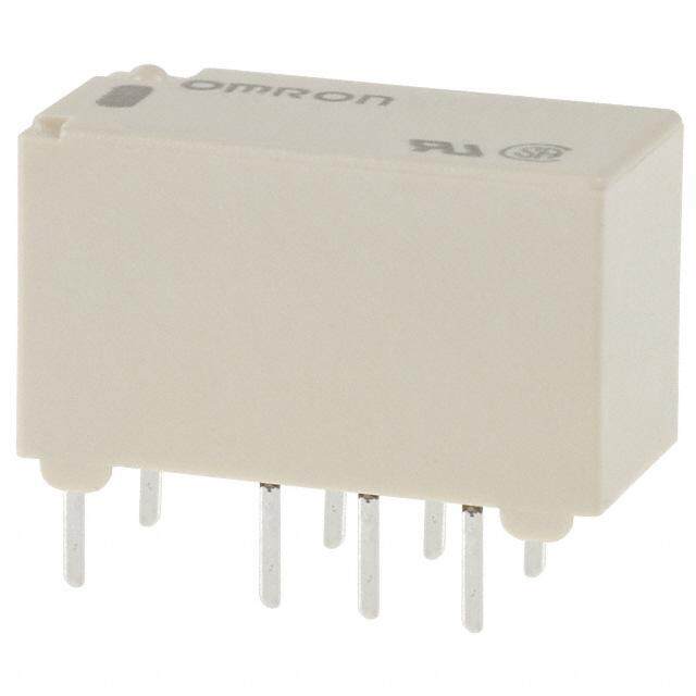
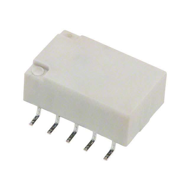
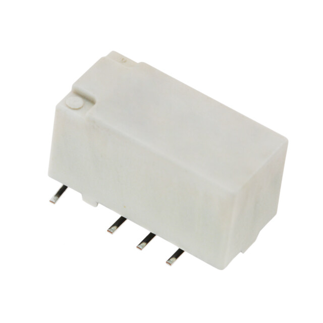
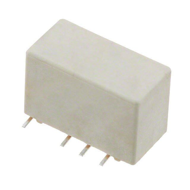
| 描述 | RELAY GEN PURPOSE SPDT 1A 12V低信号继电器 - PCB 12VDC Non-latching Single coil P1 |
| 产品分类 | |
| 品牌 | TE Connectivity |
| 产品手册 | |
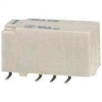
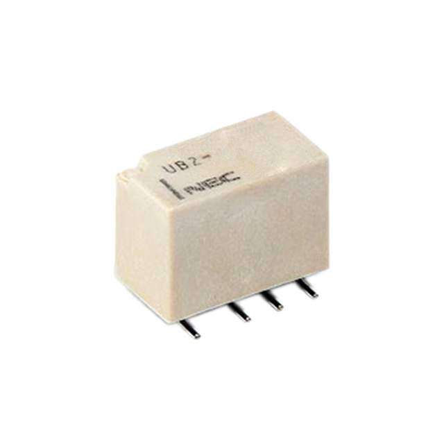
| 产品图片 |
|
| rohs | 符合RoHS无铅 / 符合限制有害物质指令(RoHS)规范要求 |
| 产品系列 | 低信号继电器 - PCB,TE Connectivity / Axicom V23026A1002B201V23026,AXICOM |
| mouser_ship_limit | 该产品可能需要其他文档才能发货到中国。 |
| 数据手册 | http://www.te.com/commerce/DocumentDelivery/DDEController?Action=srchrtrv&DocNm=108-98009&DocType=SS&DocLang=EN |
| 产品型号 | V23026A1002B201 |
| 产品 | Low Profile Relays |
| 产品目录绘图 |
|
| 产品目录页面 | |
| 产品种类 | Signal Relays |
| 介入损耗 | 1.9 dB at 900 MHz |
| 关闭电压(最小值) | 1.2 VDC |
| 其它名称 | 1393774-8 |
| 功耗 | 64 mW |
| 包装 | 管件 |
| 商标 | TE Connectivity / Axicom |
| 安装类型 | 通孔 |
| 安装风格 | Through Hole |
| 导通电压(最大值) | 9 VDC |
| 工作时间 | 2ms |
| 工作温度 | -40°C ~ 85°C |
| 工厂包装数量 | 40 |
| 开关电压 | 150VAC,125VDC - 最小值 |
| 最大开关电流 | 1 A |
| 标准包装 | 40 |
| 特性 | - |
| 特色产品 | http://www.digikey.com/cn/zh/ph/te/relays.html |
| 端子类型 | PC 引脚 |
| 端接类型 | Through Hole |
| 类型 | Miniature |
| 系列 | V23026/P1 Relay |
| 线圈功率 | 34 mW |
| 线圈电压 | 12VDC |
| 线圈电流 | 5.3mA |
| 线圈电阻 | 2.25 千欧 |
| 线圈类型 | 无锁存 |
| 绝缘 | 18 dB at 900 MHz |
| 继电器类型 | 通用 |
| 触头外形 | SPDT(1 C 型) |
| 触头材料 | 钯镍(PdNi),铑(Rh),金(Au) |
| 触点形式 | 1 Form C (SPDT-BM) |
| 触点电流额定值 | 1 A |
| 触点额定值 | 1 A |
| 释放时间 | 2ms |
| 零件号别名 | 1393774-8 |
| 额定接触(电流) | 1A |


- 商务部:美国ITC正式对集成电路等产品启动337调查
- 曝三星4nm工艺存在良率问题 高通将骁龙8 Gen1或转产台积电
- 太阳诱电将投资9.5亿元在常州建新厂生产MLCC 预计2023年完工
- 英特尔发布欧洲新工厂建设计划 深化IDM 2.0 战略
- 台积电先进制程称霸业界 有大客户加持明年业绩稳了
- 达到5530亿美元!SIA预计今年全球半导体销售额将创下新高
- 英特尔拟将自动驾驶子公司Mobileye上市 估值或超500亿美元
- 三星加码芯片和SET,合并消费电子和移动部门,撤换高东真等 CEO
- 三星电子宣布重大人事变动 还合并消费电子和移动部门
- 海关总署:前11个月进口集成电路产品价值2.52万亿元 增长14.8%
PDF Datasheet 数据手册内容提取
Signal Relays AXICOM P1 Relay V23026 n Directly triggerable with TTL standard modules as ALS, HCT & ACT n Slim line 13.5x7.85mm (0.531x0.309”) n Switching current 1 A n Bifurcated 1 form C (CO) contact n Immersion cleanable AXICOM n High sensitivity results in low noTmeliencaoml p-, oSwignearl caondn RsuF mReplatiyosn, 65 to 108-98009 Rev. E 130mW for monostable and 30 to 150mW for bistable (latching) P1 V23026 Relay n Initial surge withstand voltage 2.5kV (2/10μs) meets the Bellcore Requirement GR-1089 P1_THTSMD 1.5kV (10/160μs) meets FCC Part 68 Contact Data Typical applications Automotive equipment, CAN bus, imobilizer, office equipment, measurement Number of contacts and type 1 changeover contact and control equipment, medical equipment, safety equipment Z Contact assembly Bifurcated contact Contact material Palladium nickel, gold-rhodium covered Approvals Coil Data ULiLm 5it0in8g F icleo nNtoin. uEo 1u1s1 c4u4r1rent at max. ambient temperature Magnetic system 1 A polarized TMecahxniicmalu dmat as owf iatpcphrionvged c tuypreres nont request Coil voltage range 1 A 3 to 24VDC other coil voltages on request Maximum swichting voltage Operative range, IEC 61182150 Vdc see coil operative range Contact Data Max. coil temperature 150 Vac 85°C Contact arrangement 1 form C (CO) Thermal resistance <130K/W MMaaxx.i mswuimtch sinwgi tvcohlitnagg ec apacity 125VDC, 150VAC 30 W, 60 VA RTahteerdm couerrleenctt ric potential 1A Coil versions, THT, m<o n1o0s0t aµbVle Limiting continuous current, 85°C 1A Coil Rated Operate Release Coil Rated coil BInreitaiakli ncgo nctaapcatc rietys mistaaxn. ce / measurin sge ec omnadxi.t iDonC: l1o0ad m bAre /a 2ki0n gm cVapacity code voltage < 5v0o lmtag(cid:31)e voltage resistance power CEolenctatrcict aml aetnedriaulr ance at 12 V / 10 mA Palladium nickel, VDtyCp . 5 x 10V7D oCpmeinr. ationsVDCmin. Ω ±10% mW gold-rhodium covered 006 3 2.25 0.3 137 66 at 6 V / 100 mA typ. 1 x 10⁷ operations Contact style bifurcated contact 001 5 3.75 0.5 370 68 at 30 V / 1000 mA typ. 1 x 10⁴ operations Min. recommended contact load 10mA at 20mV 005 9 6.75 0.9 1165 70 Initial contact resistance ≤50mΩ at 10mA/20mV 002 12 9.00 1.2 2250 34 FMreeqcuheannciyc aolf eonpdeurartaionnc ewithout load 200 ops./s 004 24 typ. 109 o1p8e.0ra0t ions 2.4 4500 128 Operate/release time max. 2ms All figures are given for coil without pre-energization, at ambient temperature +23°C. UL contact ratings 30 Vdc / 1 A Set/reset time max. 2ms 65 Vdc / 0.46 A Bounce time max. 3ms Coil versions, SMT, monostable 150 Vac / 0.46 A Electrical endurance Coil Rated Operate Release Coil Rated coil at 12V/10mA typ. 50x106 operations code voltage voltage AXvIoCltaOgeM resistance power at 6V/100mA typ. 10x106 operations VDC VDCmin. TelecoVmD-,C Smiginna. l and RΩF R ±e1la0ys% mW 108-98009 Rev. E at 30V/1000mA typ. 10x103 operations 026 3 2.25 0.3 113 80 Contact ratings 021 5 3.75 P1 V02.53 026 R31e3 lay 80 UL contact ratings, resistive load 30VDC/1A 025 9 6.75 0.9 1015 80 65VDC/0.46A 022 12 9.00 1.2 1800 80 M ax. DC Load Breaking C apaci1t5y0VAC/0.46A 024 24 18.00 2.4 4500 128 Mechanical endurance typ. 109 operations AllC figouriels O arep geivrean tfoirn cgoil wRitahonutg pere-energization, at ambient temperature +23°C. Max. DC load breaking capacity Coil operative range, monostable DC coil U = Nominal coil voltage nom 65 mW U = Upper limit of the operative range of max. 130 mW the coil voltage (limiting voltage) when coils are continously energized Umax. at 0 A ]m Umax. at 0 A Umax. at - 1 A Uop. min. = Lower limit of the operative range of Uno the coil voltage (reliable operate / voltage) U ge [ Urel. min. = Lower limit of the operative range of Volta tvhoelt acgoeil )voltage (reliable release oil Unom. nominal coil voltage C Uop. min. Urel. min. Ambient Temperature [°C] 1 03-2017, Rev. 0317 Datasheets and product specification Datasheets and prodUumcatx d. -a 5t a% icso isl duubtyje act 1t tAo the Datasheet63s,52 p mmroWWdu cLLtaa dttccahhtaiinn, gg‘Definitions’ sec- www.te.com according to IEC 61810-1 and to be used terms of the disclaimer and all chapters of tion, application notes and all specifications © 2011 Tyco Electronics Corporation, only together with the ‘Definitions’ section. the ‘Definitions’ section, available at are subject to change. a TE Connectivity Ltd. company http://relays.te.com/definitions U]nom Umax. - 100 % coil duty at 0 A / U e [ g a olt Umax. - 5 % coil duty at 0 A V oil C All specifications subject to change. Consult Tyco Electronics for latest specifications. Unom. nominal coil voltage 7 of 12 Uset min. Ambient Temperature [°C] All specifications subject to change. Consult Tyco Electronics for latest specifications. 5 of 12
Signal Relays AXICOM P1 Relay V23026 (Continued) Coil data (continued) Insulation Data Initial dielectric strength Coil versions, THT and SMT, bistable 2 coils between open contacts 500Vrms Coil Rated Set Reset Coil Rated coil between contact and coil 1500Vrms code voltage voltage voltage resistance power Initial surge withstand voltage VDC VDC VDC Ω ±10% mW between contact and coil 2500V 106 3 2.25 2.25 130 69 Capacitance 101 5 3.75 3.75 390 64 between open contacts max. 5pF 105 9 6.75 6.75 1200 68 between contact and coil max. 6pF 102 12 9.00 9.00 1500 96 Clearance/creepage 241) between contact and coil 0.75mm All figures are given for coil without pre-energization, at ambient temperature +23°C. between adjacent contacts 0.75mm Coils I and II are identical. 1) A nominal voltage of 24VDC is feasible with a 12VDC coil with a series resistor (1500Ω) RF Data Isolation at 100MHz/900MHz -30.0dB/-18.0dB Coil data (continued) Insertion loss at 100MHz/900MHz -0.12dB/-1.9dB AXICOM Voltage standing wave ratio (VSWR) Coil versions, THT, bistable 1 coil at 100MHz/900MHz 1.06/1.75 Telecom-, Signal and RF Relays 108-98009 Rev. E Coil Rated Set Reset Coil Rated coil code voltage voltage P1 vVolt2ag3e0 26re sRisteanlcae y power VDC VDC VDC Ω ±10% mW Other Data 056 3 2.25 -2.25 300 30 Material compliance: EU RoHS/ELV, China RoHS, REACH, Halogen content 051 5 3.75 -3.75 740 34 refer to the Product Compliance Support Center at 0C57o il Opera9t ing Rang6.e75 -6.75 2160 38 www.te.com/customersupport/rohssupportcenter 052 12 9.00 -9.00 4500 32 Ambient temperature -40 to +85°C 054 24 18.00 -18.00 4500 128 Category of environmental protection, U = Nominal coil voltage nom IEC 61810 RT III - immersion cleanable 65 mW U V i bratio=n reUspisptaenrc leim (fiut nocf ttiohnea ol)p erativ e rang2e0 go,f 200 to 2000Hz max. 130 mW the coil voltage (limiting vo ltage) 40g, 10 to 200Hz Coil data (continued) Shock r esiswtahnecne c (ofuilnsc atioren aclo) ntinously energized Umax. at 0 A IEC 60068-2-27 (half sine) 50 g Coil ve]mrsions,U SmMaxT. a, tb 0is tAable 1 coil Umax. at - 1 A Uop. mTeinr.m ina=l tyLpoe wer limit of the operativ PeC rBan tgerem oinf a ls and SMT terminals Coil Uno Rated Set Reset Coil Rated coil Weight the coil voltage (reliable o perate max. 2g code / voltage voltage voltage resistance power Resista ncev tool tsaogled)ering heat THT U 051 ge [ VD5 C V3D.7C5 V-3D.7C5 Ω 7±4100 % m3W4 Urel. m Rien.Is E isCta 6=n0c 0eL6 to8ow- 2seo-2rld 0liem rinitg o hf ethaet SoMpeTr ativ e range of2 65 °C/10s A0 5n2om Voltainal voltage1 2of 24V is feasib9le. 0w0it h a 12V c-o9il .w0i0th a series 4re5si0to0r (4500Ω) 32 MoIiEsCtu r6 e0 s0etv6hno8esl-ti 2atciv-go5eei8l )lev voeltla, gJEeD (rEeCli aJb-Slet dr-e 0le2a0sDe see reMfloSwL3 p rofile Other cooil il voltagesU onno mre. qnuoesmt inal coil voltage Washing not recommended All figureCs are given for coil without pre-energization, at ambient temperature +23°C. Ultrasonic cleaning possible Coils I and II are identical. Uop. min. Packaging unit Urel. min. THT 2000 pcs. SMT 2400 pcs. Ambient Temperature [°C] Coil operative range, bistable Umax upper limit of the operative range of the coil voltage (limiting voltage) when coils are Umax. - 5 % coil duty at 1 A 65 mW Latching 32 mW Latching U]nom Umax. - 100 % coil duty at 0 A / U e [ g a olt Umax. - 5 % coil duty at 0 A V oil C Unom. nominal coil voltage Uset min. Ambient Temperature [°C] continuously energized. Uop min lower limit of the operative range of the coil voltage (reliable operate voltage). Urel min lower limit of the operative range of the coil voltage (reliable release voltage). 2 03-2017, Rev. 0317 Datasheets and product specification Datasheets and product data is subject to the Datasheets, product data, ‘Definitions’ sec- www.te.com according to IEC 61810-1 and to be used terms of the disclaimer and all chapters of tion, application notes and all specifications © 2011 Tyco Electronics Corporation, only together with the ‘Definitions’ section. the ‘Definitions’ section, available at are subject to change. a TE Connectivity Ltd. company http://relays.te.com/definitions All specifications subject to change. Consult Tyco Electronics for latest specifications. 5 of 12
AXICOM AXICOMAXICOM Telecom-, Signal anTde lReFco Rme-l,a Sysignal anTedl eRcFo mRe-,l aSyigsnal and RF Relays 108-98009 Rev. E108-98009 Rev. 1E08-98009 Rev. E P1 V2302P61 VRe2l3a0y2P61 VR2e3la0y26 Relay AXICOM Telecom-, Signal and RF Relays 108-98009 Rev. E DimensionDsim ensionPDs1im V e2n3si0on2s6 R elay DimensionDs iimn emnmsionDsi mine mnsmions in mm AXICOM AXICOM TeleTcoHmT-, Signal and RFT HReTlays THT SMT 10S8M-9T8009 Rev. ESMT Telecom-, Signal and RF Relays 108-98009 Rev. E Dimensions V23026-x1xxx-VB22300126-x1xxx-VB22300126-x1xxx-B201 V230D26i-mx1exxnx-sVBi22o30n012s6 i-nx1 xmxxm-VB22300126-x1xxx-B201 P1 V23026 Relay mm P1m Vm23026imn cRmhelay inch inch mm mm minmch inch inch L 13L.00 ± 0.10 1L3.00 ± 0.100.51132. 0±0 0 ±.0 00.4100.512 ± 0.004 0.512 ± 01.030.440 ± 0.10 13.40 ± 0.10 01.35.2480 ±± 00..10004 0.528 ± 0.0040.528 ± 0.004 W W7.60 ± 0.10THTW7.60 ± 0.100.2979. 6±0 0 ±.0 00.4100.299 ± 0.004 0.299 ± 0.070.745 ± 0.10SMT7.75 ± 0.10 0.73.0755 ±± 00..10004 0.305 ± 0.0040.305 ± 0.004 H 6H.9V02 3–0 02.62-0x1xxH6x.-9B0 2 0–1 0.200.2762. 9–0 0 –.0 00.8200.272 – 0.008 0.272 – 0.080.080V –2 3 00.2206-x1x8x.x0-0B –2 0 01.20 0.83.1050 –– 00..20008 0.315 – 0.0080.315 – 0.008 DDiimmeeTnnssii oonnssmm 3T.50 – 0.20 T3.50 – 0.2i0n0c.1h338. 5–0 0 –.0 00.8200.138 – 0.0080.138 –m 0m.008N/A DDiimmN/Aeennssiiooinnncshs NiinnN/A/ Ammmm N/A N/A L T1 13.00 ±T 1 0N.1/A0 T1N/A0.512 ± 0.0N0N4//AA N/A 13N.4/A0 1±0 0.9.10 0 – 0.50 1 0.90 – 00..55028 01±.0 4 0.29.900 0 –– 4 00..50020 0.429 – 0.0200.429 – 0.020 W T2 7.60 ±T5 2 0.0.18 0 ± 0.15 T52.08 0±. 2 09.195 0±. 2 00.500. 00±48 0 ±.0 00.6150.200 ± 0 .006 0.2007 .±7 5 0 .±05 0 0.06.18 0 ± 0.15 5.08 ± 00..13505 0±.5 2 0.00.008 0 ±± 4 00..10506 0.200 ± 0.0060.200 ± 0.006 H S 6.90 –0S 0.3.20 0 ± 0.1T0THH TTS0.30 0±. 2 07.120 0–. 0 01.020. 03±80 0 ±.0 00.4100.012 ± 0 .0040.0128 .±0 0 0 .–0 0 0N4./2A0 SSMM TTN/A 0.315 – 0N./0NA0/8A N/A N/A T S1 3.50 –S 01NVV.2/22A033002266--xx11 xxxSxxx1--NBB/22A000.11138 – 0.0N0N8//AA N/A NN/A/A0.85VV 2±23 3 000.212606--xx11xx0xx.xx8--5BB 2±20 0 011.10 N0/.A00.3835 ±± 00..10004 0.033 ± 0.0040.033 ± 0.004 mm inch mm inch T1 S2 mN/mAS2N/A S2N/A iNnc/Ah NN//AA N/A 10N.9m/A0m –0 0.2.50 0 – 0.15 0.20 – 00..14529in 0–c.0h 0 0.02.800 2 –– 0 00..10506 0.008 – 0.0060.008 – 0.006 L 13.00 ± 0.10 0.512 ± 0.004 13.40 ± 0.10 0.528 ± 0.004 TL2 135..0008 ±± 0 0..1105 00..521020 ±± 00..000046 135..4008 ±± 0 0..1105 00..522080 ±± 00..000046 W 7.60 ± 0.10 0.299 ± 0.004 7.75 ± 0.10 0.305 ± 0.004 WS 70..6300 ±± 0 0..1100 00..209192 ±± 00..000044 7.N7/5A ± 0.10 0.305N ±/A 0.004 H 6.90 – 0.20 0.272 – 0.008 8.00 – 0.20 0.315 – 0.008 SH1 6.N90/A – 0.20 0.272N –/ A 0.008 80..0805 –± 0 0..1200 00..301353 –± 00..000084 T T HT Versio3n.50T –H 0T. 2V0ersion THT Ve0r.s1i3o8n – 0.008 SMT VeNrs/Aion SMT VersionSMT VerNsi/oAn ST2 3.N50/A – 0.20 0.138N –/ A 0.008 0.2N0/ A– 0.15 0.008N –/A 0.006 T1 N/A N/A 10.90 – 0.50 0.429 – 0.020 T1 N/A N/A 10.90 – 0.50 0.429 – 0.020 T2 5.08 ± 0.15 0.200 ± 0.006 5.08 ± 0.15 0.200 ± 0.006 T2 5.08 ± 0.15 0.200 ± 0.006 5.08 ± 0.15 0.200 ± 0.006 S 0.30 ± 0.10 0.012 ± 0.004 N/A N/A S 0.30 ± 0.10 0.012 ± 0.004 N/A N/A THS1T Version N/A NS/iAgnal Relays S MT Versio0.n85 ± 0.10 0.033 ± 0.00A4XICOM S1 N/A N/A 0.85 ± 0.10 0.033 ± 0.004 SS22 NN//AA 13.0±0.1 13.0±7NN0.6.//1AA0±0.1 13.0±70..610±0.1 7.60±000..1.212300. 4––± 0 0 0...11155 13.4 ±70.7.15±0.100..00001388. 4––± 7 00 0..7..100500±660.1 7.75±0.1 TTHHTT VVeerrssiioonn 0.3±0.113.0±0.1 0.3±0.1 6.9-0.27.60±0.P10.3±0.11 Re6.9-0.2lay V23026 (C6.9-0.2oSnStMMinuTTe d VV)85±0.1ee1rr3ss.4iioo±0nn.1 85±0.1 7.78.0-0.25±0.1 85±0.1 8.0-0.2 8.0-0.2 DTHimT evnesrsioionn0.3±0.1s 1133..00±±00..11 6.9-0.22 3.5-0.277..6600±±005..11.08±0.13.5-0.25 5.08±0.3.5-0.215S0.85±0.1MT v5e0..r110s338io..±44n0±±.001..511 50.8.0-0.2 0.2-0.1577..577.0558±±±000...1111550.0.89±0.-00..1550.2-0.15 150.0.89±-00..1550.2-0.15 150.0.89±-00..155 0. 1 MVieowun MV(ottoinieonptwuog v n tohihtenioe0.3±0.1wn0.3±0.1tl oge)c o tlhhamoeypMV(lo etcooui oeonlptamwue yvn npooitteoun iswnnttioegd) ne thht6.9-0.2 3.5-0.26.9-0.23.5-0.23.5- ooesMV(fl it edcoiteoh oeplwuaem ovyn Popfi5o55te .no..tCiu000whntn888tBoeg)±±±e 000 tnPh.h..111tCoe 555sl Beicd oleam yopof outhntee nPt CsiBde ofSV 0.85±0.10.85±0.1toiheledw eP SV(ortCoo ineplpBtdwao ved toirh el napewty ao)cod otuh mlta0.2-0.15e0.2-0.150.2-0.pySV( tcooo8.0-0.2o8.0-0.2ioenulpmdwet ve np111oir55teo000. .n 00p.sw..n89899t±ia±o-e--d)00000d .n.e.1..t1555h5 5t l oaesSV(fy it docoiotehoelpudwem tove Popfire notCpwhtnBaoe)ed tnPh ltCae sy Bicodouem topf othnee nPt CsiBde of the PCB (top PvCieBw la)yout (top view) MMoouuTTnnOHttTPii n nvvegigerws hhio oononll eeco llmaapyyooonuuenttt side of PCB 5.08 5.08 SSSooMlld5.08dT eeverrr sppioaandd llaayyoouutt 5.08 5.08 5.08 View onto the component side of the PCB View onto the component side of the PCB View onto the component side of the PCB View onto the component side of the PCB (top view) (top view) (top view) (top view) 5.08 5.08 Terminal assigTenrmmeinntal assiTgenrmmeinnatl assignment Relay – top viRewelay – top vRieewla5.085.08y – top view 5.085.08 Contact releasCeo notra rcets reetl ecaoCsneod niottiroa ncret, srceeoltie lc aposonelda oirtirito yrn et,os ce sote iclt o ptnhodelai trriieotylna ,ty oc osiel tp tohlea rriteyl atoy set the relay Terminal assignment Non-latchingN tyopne-latchingN toynpL-ealattcchhiningg t tyyppeLe, a1t cchoiinlg typeL,a 1tc Lchoaintilcgh tinygp et,y 1p ecL,o a2itl cchoiinlsg typeL,a 2tc choinilsg type, 2 coils RelaTye r–m itnoapl avsiseiwgnment Contancott reenleearsgeiz eodr n rceoost needtn icteioorgnnidzietidon noc,ot cneroednisilet eiprotgo ncilzaoernidtdy ci ttoioon nrsdeeisttie otthn ceo rnedlaityiorneserte csoent dciotinodnitionreset conditiorneset condition Monostable version Bistable version, 1 coil Bistable veCrsioonn,t 2a ccotsils are sChoonwtanc itns are Cshoonwtanc tisn are shown in TNTeeorrmnm-iilnnataacllr h eaasissnt sscgiiogg ntnndyimmtpioeneenntt Latching type, 1 coilreset conditioLnatching type, 2 coils reset condirtieosnet conditionre. sBeot tcho nditiorne.s Beto ctho ndition. Both Relay – top view coils can be ucsoeidls eciathne br e ucsoeilds ecaithne bre used either Relay – top view not energized condition reset condition reset condition as set or reseat sc osiel.t or reseats c soeil.t or reset coil. CCoonnttaacctt rreelleeaassee oorr rreesseett ccoonnddiittiioonn,, ccooiill ppoollaarriittyy ttoo sseett tthhee rreellaayy Contacts are shown in reset condition. Both NNoonn--llaattcchhiinngg ttyyppee LLaattcchhiinngg ttyyppee,, 11 ccooiill LLaattcchhiinngg ttyyCpopneeta,,c t22s accreoo siihllosswn in reset coils can be used either condition. Both coils can be used nnoott eenneerrggiizzeedd ccoonnddiittiioonn rreesseett ccoonnddiittiioonn rreesseett ccoonnddieCittitoiihoonetnrna cats psoest iotior nre mseigt hcto cil.hange Caso nsteatc otsr raersee st hcoowil.n in during transportation and must be Contacts are shown in reset before use. reset condition. Both reset condition. Both All specifications Aslul bsjpeecct itfioc achtioannsgA esl.lu Csbpjoeenccsti ufitoclta cTthiyoacnons g Eselu.e bCcjteorocnnts itucols tc Tfhoyarc nloag tEee.ls eCtc sotrpnoesncuicilfits cT afyotciro olna Este.l esct tsropneiccisfi cfaotri olantse.s t specificatcioonisl.s can be used either 4 of 12 4 of 12 4 of 12 coils can be used either as set or reset coil. as set or reset coil. All specifications subject to change. Consult Tyco Electronics for latest specifications. 4 of 12 AAllll ssppeecciifificcaattiioonnss ssuubbjjeecctt ttoo cchhaannggee.. CCoonnssuulltt TTyyccoo EElleeccttrroonniiccss ffoorr llaatteesstt ssppeecciifificcaattiioonnss.. 44 ooff 1122 3 03-2017, Rev. 0317 Datasheets and product specification Datasheets and product data is subject to the Datasheets, product data, ‘Definitions’ sec- www.te.com according to IEC 61810-1 and to be used terms of the disclaimer and all chapters of tion, application notes and all specifications © 2011 Tyco Electronics Corporation, only together with the ‘Definitions’ section. the ‘Definitions’ section, available at are subject to change. a TE Connectivity Ltd. company http://relays.te.com/definitions
AXICOM Telecom-, Signal and RF Relays 108-98009 Rev. E AXICOM P1 V23026 Relay Telecom-, Signal and RF Relays 108-98009 Rev. E PA1X VIC2O3M02P6a cRkienglay AXICOM Dimensions in mm Telecom-, Signal and RF Relays Telecom-, Signal and RF Rela1ys08-98009 Rev. E 108-98009 Rev. E P1 V23026 Relay P1 V23026 Relay Recommended Soldering Conditions AXICOM Packing Dimensions in mm SRoeldceorinmg mconednitdioensd a Scocolrddeinrgi nIETgeCle C c6omo0-0n, 5Sdi8gn-iSa2tlii -ago5nn8dna RalsF nR Rdee llaayyss AXICOM 10A8-9X80I0C9 OReMv. E IPC/JEDEC J-STD-020B P1 V23026 Relay ATeleXcoImC-, OSigMnal and RF Relays 108-98009 Rev. E Soldering conditions according IEC 60058-P21-5 R8e alanyd V23026 (Continued) TPele1c omV-, 2Sig3nal0 an2d R6F R eRlayes lay 108-98009 Rev. E IPC/JEDEC J-STD-020B P1 V23026 Relay 20 - 40 sec Full line: typical Recommended Soldering CoDnottdedi ltinieo:pnrocsess limits 240 °C Processing PaPcackkiningg Dimensions in mm 20 - 40 sec Full line: typical Packing Dimensions in mm SoldReecroinmgm ecnodnedd istiooldnesrin ag cccoondridtioinngs IEC 60D0o5tte8d- l2in-e5:p8ro acenssd li mits IPCC/JEDE1C284 00J ° °-CCSTD-020B mperature °°CSIPoCld/JeErinDgE111 Cc308o00 0J n°° -°dCCSCitTioDn-s0 2a0cBcording IEC 60058-2-58 and fcoorocleindg T4u0b ree lfaoyrs T pHeTr tvuebrsei,o 2n000 relays per box T420‘u0 b0ree0 l afroyersl aT pyHesT rp tveuerb rbeso ioxn Teerature 213400 °°CC 20 - 40 sec FDuoltl tleinde l:ine:fctpooyrrpoocilcecinedagsls limits p 100 °C m e Tube for THT version T Vapor Phase Soldering: Temperature/Time Profile 40 relays per tube 180 °C °C (Lead and Housing Peak Temperature) 2‘000 relays per box e ur 130 °C forced erat cooling Vapor Phase Soldering: Temperature/Time Profile mp 100 °C (Lead and Housing Peak Temperature) ReTesistance to soldering heat - Reflow profile 0.2 ± 8 13. TubTeu fobre T fHorT T vHerTs ivoenr sion Resistance to soldering heat - Reflow profile 40 r4e0la yresl apyesr tpuebre tube Vapor Phase Soldering: Temperature/Time Profile 2‘0020‘0 r0e0la yres lpaeyrs bpoexr box Vapor Phase Soldering: T(aLpeea adnd a rneedl foHr oSuMsTi nvegrs Pioneak Temperature) Tape and reel for SMT version Resistance to soldering heat - Reflow profile taenmd pheoruastuinreg/ tpimeaek p treomfilpee (rleaatudr e) 480 relay1s1 .p6±e0r .2reel, 2400 relays per box 8±0.2 428‘400 0re plaeyrs b poexr reel 3. R°Cesistance to soldering heat - Reflow profile 1 e ur at er Tempure °C 11.6±0.2 T4a8p0e r ealnadys r epeelr froere Sl MT version Temperat Time (s) Reel dimension Infrared Soldering: Temperature/Time Profile 13.8±0.213.8±0.2 2‘400 per box °C (Lead and Housing Peak Temperature) e ur Tape and reel for SMT version erat Time (s) ReIenlf draimreedn sSioonldering: Tem11p.6±e0r.2ature/Time Profile 480T raeplaey sa npde rr reeeel l for SMT version Rmpecommended reflow soldering profile (Lead and Housing Pe1a1.6k± 0T.2emperature) 2‘40408 p0e rre blaoyxs per reel Te Infrared Soldering: temperature/ 2‘400 per box time profile (lead and housing peak temperature) Recommended reflow soldering profile Reel dimensions Recommended reflow soldering profile Infrared Soldering: Temperature/Time Profile Time (s) R(eLeel daidm eannsdio Hnousing Peak Temperature) Reel dimension C Re °ecommended reflow soldering profile ur at perC m° Teure All specifications subject to change. Consult Tyco Electronics for latest specifications. 10 of 12 at er p m e T C Infrared Soldering: Temperature/Time Profile ° Time (s) e (Lead and Housing Peak Temperature) ur at All specifications subject to change. Consult Tyco Electronics for latest specifications. 10 of 12 mper Time (s) Infrared Soldering: Temperature/Time Profile e (Lead and Housing Peak Temperature) T All specifications subject to change. Consult Tyco Electronics for latest specifications. 10 of 12 Infrared Soldering: Temperature/Time Profile Time (s) All s(pLeeciaficdat iaonnsd su Hbjeocut tso icnhgan Pgee. Caokn sTuelt mTycpoe Erleactturorneic)s for latest specifications. 10 of 12 All specifications subject to change. Consult Tyco Electronics for latest specifications. 9 of 12 All specifications subject to change. Consult Tyco Electronics for latest specifications. 9 of 12 4 03-2017, Rev. 0317 Datasheets and product specification Datasheets and product data is subject to the Datasheets, product data, ‘Definitions’ sec- www.te.com according to IEC 61810-1 and to be used terms of the disclaimer and all chapters of tion, application notes and all specifications © 2011 Tyco Electronics Corporation, only together with the ‘Definitions’ section. the ‘Definitions’ section, available at are subject to change. a TE Connectivity Ltd. company http://relays.te.com/definitions All specifications subject to change. Consult Tyco Electronics for latest specifications. 9 of 12
Signal Relays AXICOM P1 Relay V23026 (Continued) Product code structure Typical product code V23026 A1 002 B201 Type V23026 P1 Series Signal Relay Version A1 THT, monostable D1 SMT, monostable B1 THT, bistable (latching), 2 coils E1 SMT, bistable (latching), 2 coils C1 THT, bistable (latching), 1 coil F1 SMT, bistable (latching), 1 coil Coil Coil code: please refer to coil versions table Contacts B201 1 form C, 1 CO Product Code Version Coil Coil voltage Part Number V23026A1006B201 THT version monostable 3VDC 1-1393774-7 V23026A1001B201 5VDC 1393774-1 V23026A1005B201 9VDC 1-1393774-5 V23026A1002B201 12VDC 1393774-8 V23026A1004B201 24VDC 1-1393774-2 V23026B1106B201 bistable, 2 coils 3VDC 1393775-3 V23026B1101B201 5VDC 3-1393774-4 V23026B1105B201 9VDC 1393775-2 V23026B1102B201 12VDC 3-1393774-5 V23026C1056B201 3VDC 2-1393774-6 V23026C1051B201 5VDC 2-1393774-0 V23026C1057B201 9VDC 2-1393774-7 V23026C1052B201 12VDC 2-1393774-1 V23026C1054B201 24VDC 2-1393774-4 V23026D1026B201 SMT version monostable 3VDC 1393776-8 V23026D1021B201 5VDC 1393776-3 V23026D1025B201 9VDC 1422015-9 V23026D1022B201 12VDC 1393776-4 V23026D1024B201 24VDC 1393776-7 V23026E1106B201 bistable, 2 coils 3VDC 1393777-3 V23026E1101B201 5VDC 1422015-6 V23026E1105B201 9VDC 1393777-2 V23026E1102B201 12VDC 1393776-9 V23026F1051B201 9VDC 1422015-8 V23026F1052B201 12VDC 4-1393774-3 5 03-2017, Rev. 0317 Datasheets and product specification Datasheets and product data is subject to the Datasheets, product data, ‘Definitions’ sec- www.te.com according to IEC 61810-1 and to be used terms of the disclaimer and all chapters of tion, application notes and all specifications © 2011 Tyco Electronics Corporation, only together with the ‘Definitions’ section. the ‘Definitions’ section, available at are subject to change. a TE Connectivity Ltd. company http://relays.te.com/definitions