
 Datasheet下载
- 型号: ULT-12/2.5-D48NM-C
- 制造商: Murata
- 库位|库存: xxxx|xxxx
- 要求:
| 数量阶梯 | 香港交货 | 国内含税 |
| +xxxx | $xxxx | ¥xxxx |
查看当月历史价格
查看今年历史价格
ULT-12/2.5-D48NM-C产品简介:
ICGOO电子元器件商城为您提供ULT-12/2.5-D48NM-C由Murata设计生产,在icgoo商城现货销售,并且可以通过原厂、代理商等渠道进行代购。 ULT-12/2.5-D48NM-C价格参考。MurataULT-12/2.5-D48NM-C封装/规格:直流转换器, 隔离模块 DC/DC 转换器 1 输出 12V 2.5A 36V - 75V 输入。您可以下载ULT-12/2.5-D48NM-C参考资料、Datasheet数据手册功能说明书,资料中有ULT-12/2.5-D48NM-C 详细功能的应用电路图电压和使用方法及教程。
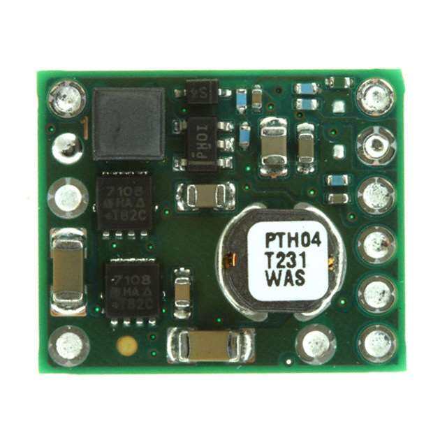
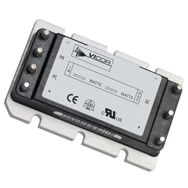
Murata Power Solutions Inc.生产的直流转换器型号ULT-12/2.5-D48NM-C,是一款高效、紧凑型的非隔离DC-DC转换器模块。该型号的主要应用场景包括:

1. 通信设备:适用于基站、路由器和交换机等通信设备中的电源管理,提供稳定且高效的12V输出电压,满足通信系统对电源可靠性和效率的要求。

2. 工业自动化:在工业控制领域,例如PLC(可编程逻辑控制器)、传感器和执行器中,该转换器能够为各种负载提供稳定的电源支持,适应恶劣的工业环境。

3. 数据存储设备:用于服务器、存储阵列和其他数据中心设备中,确保关键组件如硬盘驱动器、固态硬盘和内存模块获得持续稳定的电力供应。

4. 医疗设备:在便携式或固定式医疗设备中,例如监护仪、超声波设备等,该转换器可以提供精确的电压输出,保障设备的正常运行。

5. 嵌入式系统:广泛应用于各种嵌入式计算平台,如单板计算机、工控机等,为其处理器、芯片组和其他外围设备供电。

6. 物联网(IoT)设备:为低功耗的IoT节点和网关提供电源支持,确保其在网络连接和数据采集方面的稳定性。

ULT-12/2.5-D48NM-C具有较高的功率密度和良好的热性能,能够在宽输入电压范围(36V至75V)内工作,并提供12V输出电压,最大输出电流为2.5A。其紧凑的设计和高可靠性使其非常适合需要高效电源解决方案的各种应用场合。此外,该转换器还具备短路保护、过压保护和过温保护等功能,进一步提升了系统的安全性和稳定性。
| 参数 | 数值 |
| 产品目录 | |
| 描述 | DC/DC CONVERTER 12V 2.5A 30W隔离式DC/DC转换器 30W 48Vin 12Vout 2.5A NegPolarity SMT |
| 产品分类 | DC DC ConvertersDC/DC转换器 |
| 品牌 | Murata Power Solutions Inc |
| 产品手册 | |
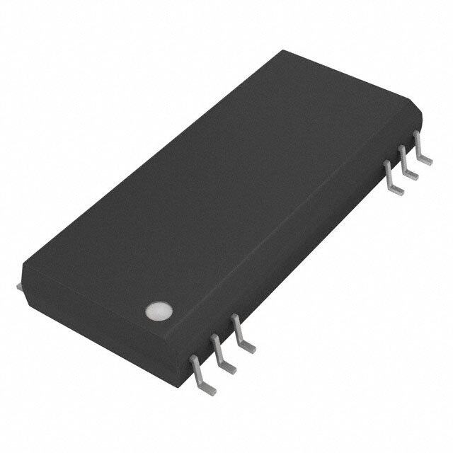
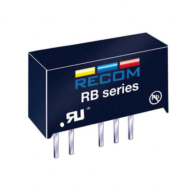
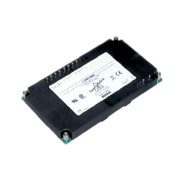
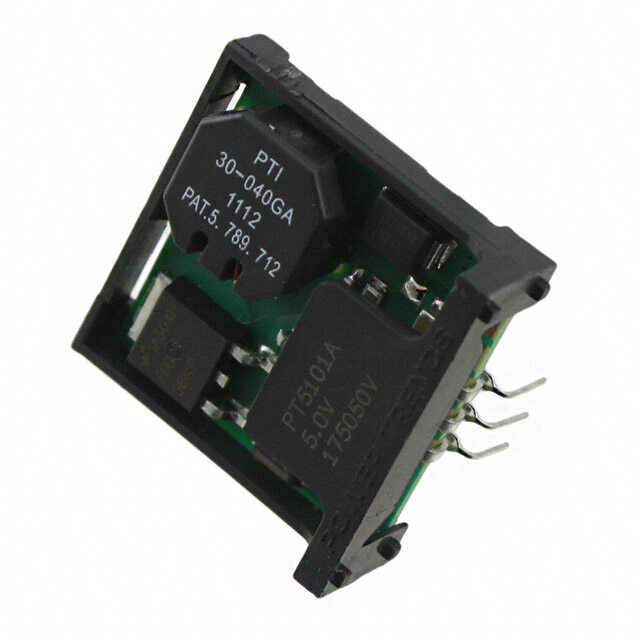
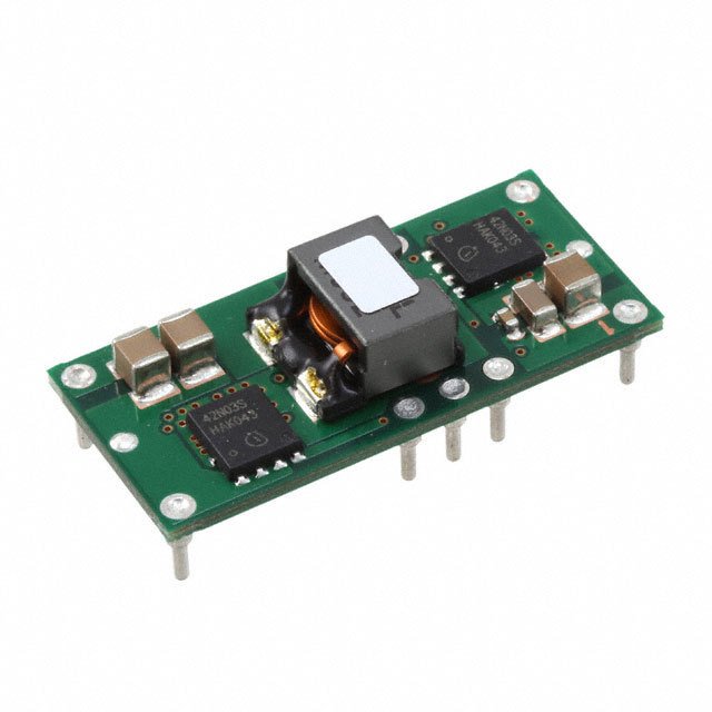
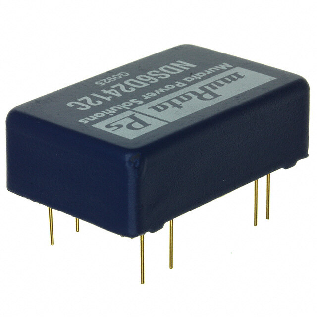
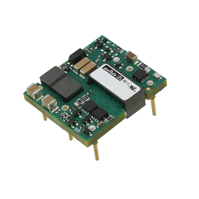
| 产品图片 |
|
| rohs | 符合RoHS无铅 / 符合限制有害物质指令(RoHS)规范要求 |
| 产品系列 | 隔离式DC/DC转换器,Murata Power Solutions ULT-12/2.5-D48NM-CULT |
| 数据手册 | |
| 产品型号 | ULT-12/2.5-D48NM-C |
| 产品 | Isolated |
| 产品种类 | 隔离式DC/DC转换器 |
| 其它名称 | 811-2324-2 |
| 功率(W)-制造系列 | 30W |
| 功率(W)-最大值 | 30W |
| 包装 | 带卷 (TR) |
| 单位重量 | 9.072 g |
| 商标 | Murata Power Solutions |
| 大小/尺寸 | 0.92" 长 x 0.75" 宽 x 0.35" 高(23.4mm x 19.1mm x 8.9mm) |
| 安装类型 | 表面贴装 |
| 宽度 | 0.75 in |
| 封装/外壳 | 8-SMD 模块,1/32 砖 |
| 封装/箱体尺寸 | 1/32 Brick |
| 尺寸 | 0.92 in x 0.75 in x 0.35 in |
| 工作温度 | -40°C ~ 85°C |
| 工厂包装数量 | 200 |
| 效率 | 91% |
| 标准包装 | 200 |
| 特性 | 具有远程开/关功能和 UVLO |
| 电压-输入(最大值) | 75V |
| 电压-输入(最小值) | 36V |
| 电压-输出1 | 12V |
| 电压-输出2 | - |
| 电压-输出3 | - |
| 电压-隔离 | 1.5kV(1500V) |
| 电流-输出(最大值) | 2.5A |
| 类型 | 隔离模块 |
| 绝缘电压 | 1.5 kV |
| 输入电压—公称值 | 48 V |
| 输入电压范围 | 36 V to 75 V |
| 输出功率 | 30 W |
| 输出数 | 1 |
| 输出电压—通道1 | 12 V |
| 输出电流—通道1 | 2.5 A |
| 长度 | 0.92 in |
| 高度 | 0.35 in |


- 商务部:美国ITC正式对集成电路等产品启动337调查
- 曝三星4nm工艺存在良率问题 高通将骁龙8 Gen1或转产台积电
- 太阳诱电将投资9.5亿元在常州建新厂生产MLCC 预计2023年完工
- 英特尔发布欧洲新工厂建设计划 深化IDM 2.0 战略
- 台积电先进制程称霸业界 有大客户加持明年业绩稳了
- 达到5530亿美元!SIA预计今年全球半导体销售额将创下新高
- 英特尔拟将自动驾驶子公司Mobileye上市 估值或超500亿美元
- 三星加码芯片和SET,合并消费电子和移动部门,撤换高东真等 CEO
- 三星电子宣布重大人事变动 还合并消费电子和移动部门
- 海关总署:前11个月进口集成电路产品价值2.52万亿元 增长14.8%


PDF Datasheet 数据手册内容提取
ULT Series www.murata-ps.com Thirty-Second-Brick Isolated DC/DC Converters with 2:1 Wide Input Range FEATURES 2:1 Input Voltage Range (36V – 75V, 48 Volts, Typical units nominal) Up to 30W output power @ 36 – 48 – 75Vin 89% effi ciency (typical, 5Vout) PRODUCT OVERVIEW Through-hole and optional SMT package The ULT Series isolated DC/DC converter repre- Modules will supply an output power of up to Miniature 1/32 brick open frame package sents the next generation converters in a 1/32 30 watts over the input range of 36-75V. The ULT Positive & Negative Logic On/Off control option brick package. This converter is the “industry- Series also provides a cost effective approach to Over-current & Over-temperature protection standard” 1/32 brick form factor (0.92" x 0.75" highly effi cient systems requiring 12V, 5V, and 3.3V Low output ripple and noise x 0.35"). The product fully complies with RoHS-6 voltages, eliminating the requirement for a “Bus directive. Converter” and multiple PoL converters. The ULT Strong thermal derating characteristics The thirty-second brick is offered as an open family provides basic insulation with 1500Vdc iso- Operational Temperature Range –40°C to +85°C frame module; mounting options include through- lation meeting the requirements of UL/IEC 60950. 1500V I/O isolation hole or surface mount (SMT) pinouts. Typical The ULT series modules are DOSA compatible applications include Optical Networking Equipment, industry standard 1/32 brick. Tight line/load regulation Wireless Base Station applications, Microwave Certifi ed to UL/IEC 60950-1, CAN/CSA C22.2 No. Radio communications, and Telecom and Data 60950-1, safety approvals, 2nd Edition Equipment applications. F1 +Vin (1) (cid:42)(cid:84)(cid:80)(cid:77)(cid:66)(cid:85)(cid:74)(cid:80)(cid:79) +Vout (8) Barrier (cid:116)(cid:1)(cid:52)(cid:88)(cid:74)(cid:85)(cid:68)(cid:73)(cid:74)(cid:79)(cid:72) (cid:12)(cid:52)(cid:70)(cid:79)(cid:84)(cid:70)(cid:1)(cid:9)(cid:24)(cid:10) External (cid:116)(cid:1)(cid:39)(cid:74)(cid:77)(cid:85)(cid:70)(cid:83)(cid:84) DC On/Off Power Control Controller (cid:116)(cid:1)(cid:36)(cid:86)(cid:83)(cid:83)(cid:70)(cid:79)(cid:85)(cid:1)(cid:52)(cid:70)(cid:79)(cid:84)(cid:70) Source (2) and Power (cid:53)(cid:83)(cid:66)(cid:79)(cid:84)(cid:71)(cid:70)(cid:83) (cid:14)(cid:52)(cid:70)(cid:79)(cid:84)(cid:70)(cid:1)(cid:9)(cid:22)(cid:10) Open = On Reference and (cid:36)(cid:77)(cid:80)(cid:84)(cid:70)(cid:69)(cid:1)(cid:30)(cid:1)(cid:48)(cid:71)(cid:71) Error Amplifier (cid:9)(cid:49)(cid:80)(cid:84)(cid:74)(cid:85)(cid:74)(cid:87)(cid:70)(cid:1) Trim (6) polarity) -Vin (3) -Vout (4) Figure 1. Connection Diagram Typical topology is shown. Murata Power Solutions recommends an external fuse. For full details go to www.murata-ps.com/rohs www.murata-ps.com/support MDC_ULT Series.F05 Page 1 of 26
ULT Series Thirty-Second-Brick Isolated DC/DC Converters with 2:1 Wide Input Range PERFORMANCE SPECIFICATIONS SUMMARY AND ORDERING GUIDE Output Input Efficiency Package Root Model VOUT IOUT Power R/N (mV pk-pk) Regulation (max.) VIN Nom. Range IIN, no load IIN, full (V) (A, max.) (W) Typ. Max. Line Load (V) (V) (mA) load (A) Min. Typ. Case (inches) ULT-3.3/7.5-D48 3.3 7.5 24.75 45 50 ±0.15% ±0.2% 48 36-75 20 0.6 84% 85.5% 0.92 x 0.75 x 0.35 ULT-5/5-D48 5 5 25 50 75 ±0.1% ±0.125% 48 36-75 20 0.59 87% 89% 0.92 x 0.75 x 0.35 ULT-12/2.5-D48 12 2.5 30 70 100 ±0.075% ±0.125% 48 36-75 20 0.68 90% 92% 0.92 x 0.75 x 0.35 Please refer to the Part Number Structure when ordering. is measured with 188μF. Output caps are necessary for our test equipment and may All specifi cations are typical at nominal line voltage and full load, +25°C unless not be needed for your application. otherwise noted. See detailed specifi cations. External input capacitors are Regulation specifi cations describe output voltage deviations from a nominal/midpoint 33μF electrolytic and three 1μF ceramic. Output ripple is measured with 400μF value to either extreme (50% load step). capacitance across output pins for the 3.3Vout and 5Vout model. The 12Vout model PART NUMBER STRUCTURE ULT - 3.3 /7.5- D48 N M Lx - C Thirty-second-brick series (Unipolar) RoHS Hazardous Substance Compliance (does not claim EU RoHS exemption 7b–lead in solder) C = RoHS-6 Nominal Output Voltage Pin Length Option (Thru-hole only) Blank = Standard pin length 0.190˝ (4.8mm) L1 = 0.110˝ (2.79mm) ➀ L2 = 0.145˝ (3.68mm) ➀ Maximum Rated Output Current SMT Version Option Current in Amps Blank = Through-hole mount, no SMT M = Surface mount (MSL Rating 2) ➁ Input Voltage Range On/Off Control Logic Option D48 = 36-75 Volts (48V nominal) N = Negative P = Positive ➀ Special quantity order is required; samples available with standard pin length only. ➁ SMT (M) versions not available in sample quantities. ➂ Some model number combinations may not be available. See website or contact your local Murata sales representative. www.murata-ps.com/support MDC_ULT Series.F05 Page 2 of 26
ULT Series Thirty-Second-Brick Isolated DC/DC Converters with 2:1 Wide Input Range FUNCTIONAL SPECIFICATIONS (ULT-3.3/7.5-D48-C) ABSOLUTE MAXIMUM RATINGS Conditions ➀ Minimum Typical/Nominal Maximum Units Input Voltage, Continuous Full temperature range 36 80 Vdc Operating or non-operating, 100 mS max. Input Voltage, Transient 15 duration 100 Vdc Isolation Voltage Input to output tested 1500 Vdc Input Reverse Polarity None, install external fuse none Vdc On/Off Remote Control Power on or off, referred to -Vin 15 Vdc Output Power 25 W Output Current Current-limited, no damage, short-circuit protected 7.5 A Storage Temperature Range Vin = Zero (no power) -40 125 °C Absolute maximums are stress ratings. Exposure of devices to greater than any of these conditions may adversely affect long-term reliability. Proper operation under conditions other than those listed in the Performance/Functional Specifi cations Table is not implied or recommended. INPUT Conditions ➀ ➂ Operating voltage range 36 48 75 Vdc Recommended External Fuse 13 Fast blow 2 A Start-up threshold Rising input voltage 32.5 33.3 34.5 Vdc Undervoltage lockout (@ ½ load) 11 Falling input voltage 30.75 31.75 32.75 Vdc Turn-On/Turn-Off Hysteresis 1.22 1.3 1.32 Vdc Overvoltage shutdown Rising input voltage N/A Vdc Reverse Polarity Protection None, install external fuse None Vdc Internal Filter Type Capacitive Input current Full Load Current Conditions Vin = nominal 0.6 0.62 A Low Line Input Currrent Vin = minimum 0.8 0.83 A Inrush Transient Vin = 48V 0.05 A2-Sec. Short Circuit input current 0.04 0.1 mA No Load input current Iout = minimum, unit=ON 20 40 mA Shut-Down Mode input current (Off, UV, OT) 6 10 mA Refl ected (back) ripple current ➁ Measured at input with specifi ed fi lter 30 mA, pk-pk GENERAL and SAFETY Vin=48V 84 85.5 % Effi ciency Vin=36V 83.5 85.5 % Isolation Isolation Voltage, Input to Output 1500 Vdc Insulation Safety Rating basic Isolation Resistance 10 MΩ Isolation Capacitance 1700 pF Safety UL-60950-1, CSA-C22.2 No.60950-1, Yes (certifi ed to the following requirements) IEC/60950-1, 2nd edition Per Telcordia SR332, issue 1, class 3, ground Calculated MTBF ➃ TBD Hours x 103 fi xed, Tambient=+25°C DYNAMIC CHARACTERISTICS Fixed Switching Frequency 250 287 320 KHz Startup Time Power On, to Vout regulation band, 100% 50 mS Startup Time Remote ON to Vout Regulated 50 mS Dynamic Load Response 50-75-50% load step to 1% of Vout 75 150 μSec Dynamic Load Peak Deviation same as above ±100 mV FEATURES and OPTIONS Remote On/Off Control ➅ "N" suffi x Negative Logic, ON state ON = pin grounded or external voltage -0.7 1.0 Vdc Negative Logic, OFF state OFF = pin open or external voltage 10 15 Vdc Control Current open collector/drain 1 mA "P" suffi x Positive Logic, ON state ON = pin open or external voltage 10 15 V Positive Logic, OFF state OFF = ground pin or external voltage -0.7 1.0 V Control Current open collector/drain 1 mA www.murata-ps.com/support MDC_ULT Series.F05 Page 3 of 26
ULT Series Thirty-Second-Brick Isolated DC/DC Converters with 2:1 Wide Input Range FUNCTIONAL SPECIFICATIONS (ULT-3.3/7.5-D48-C, CONT.) OUTPUT Conditions ➀ Minimum Typical/Nominal Maximum Units Total Output Power 0 24.75 25 W Voltage Nominal Output Voltage 3.2505 3.3 3.35 Vdc Setting Accuracy At 50% load -1.5 1.5 Vdc Output Trim Range ➇ User selectable (see trim formulas) -20 10 % of Vout Overvoltage Protection 3.9 4.6 Vdc Current Output Current Range 0 7.5 7.5 A Minimum Load no minimal load required Current Limit Inception ➈ 98% of Vnom., after warmup 8.8 10.8 12.5 A Short Circuit Hiccup technique, autorecovery within ±1.25% Short Circuit Current 0.3 A of Vout Short Circuit Duration (remove short for Output shorted to ground, no damage Continuous recovery) Short circuit protection method Hiccup current limiting Non-latching Regulation ➆ Line Regulation Vin=min. to max., Vout=nom., full load ±0.15 % of Vout Load Regulation Iout=min. to max., Vin=nom. ±0.2 % of Vout Ripple and Noise 12 Tested with eight 47μF ceramic caps in parallel 45 50 mV pk-pk Temperature Coeffi cient At all outputs 0.02 % of Vout./°C Maximum Capacitive Loading Low ESR 400 5,000 μF Remote Sense Compliance Vsense = Vout - Vload, sense connected at load 10 % of Vout MECHANICAL (Through Hole Models) Conditions ➀ ➂ Minimum Typical/Nominal Maximum Units Outline Dimensions 0.92 x 0.75 x 0.35 Inches (Please refer to outline drawing) LxWxH 23.4x19.05x8.89 mm Weight 0.32 Ounces 9.07 Grams Through Hole Pin Diameter .04 & .062 Inches 1.02 & 1.57 mm Through Hole Pin Material Brass TH Pin Plating Metal and Thickness Nickel subplate 50 μ-inches Gold overplate 3-5 μ-inches ENVIRONMENTAL Operating Ambient Temperature Range ➉ See derating curves -40 85 °C Storage Temperature Vin = Zero (no power) -55 125 °C Thermal Protection/Shutdown 120 130 140 °C Electromagnetic Interference External fi lter is required Conducted, EN55022/CISPR22 B Class RoHS rating RoHS-6 www.murata-ps.com/support MDC_ULT Series.F05 Page 4 of 26
ULT Series Thirty-Second-Brick Isolated DC/DC Converters with 2:1 Wide Input Range Performance Specifi cation Notes ➀ All specifi cations are typical unless noted. Ambient temperature = ➆ Regulation specifi cations describe the deviation as the input line voltage +25°Celsius, VIN is nominal, output current is maximum rated nominal. or output load current is varied from a nominal midpoint value to either External output capacitance consists of 400μF capacitors across output extreme (50% load). pins; one 33μF low ESR, and three 1μF external input capacitors. All caps ➇ Do not exceed maximum power ratings, sense limits or output overvoltage are low ESR. when adjusting output trim values. Testing must be kept short enough that the converter does not appreciably heat up during testing. For extended testing, use plenty of airfl ow. See ➈ Output overload protection is non-latching. When the output overload derating curves for temperature performance. All models are stable and is removed, the output will automatically recover. regulate within spec without external cacacitance. ➉ All models are fully operational and meet published specifi cations, ➁ Input Ripple Current is tested and specifi ed over a 5-20 MHz bandwidth including “cold start” at –40°C. and uses a special set of external fi lters only for the Ripple Current speci- 11 The converter will shut off if the input falls below the undervoltage thresh- fi cations. Input fi ltering is CIN = 33 μF, CBUS = 220 μF, LBUS = 12 μH. Use old. It will not restart until the input exceeds the Input Start Up Voltage. capacitor rated voltages which are twice the maximum expected voltage. Capacitors must accept high speed AC switching currents. 12 Output noise may be further reduced by installing an external fi lter. See the Application Notes. Use only as much output fi ltering as needed and no ➂ Note that Maximum Current Derating Curves indicate an average current more. Larger caps (especially low-ESR ceramic types) may slow transient at nominal input voltage. At higher temperatures and/or lower airfl ow, the response or degrade dynamic performance. Thoroughly test your applica- converter will tolerate brief full current outputs if the average RMS current tion with all components installed. over time does not exceed the Derating curve. All Derating curves are presented at sea level altitude. Be aware of reduced power dissipation 13 If reverse polarity is accidentally applied to the input, always connect an with increasing density altitude. external fast blow input fuse in series with the +VIN input. ➃ Mean Time Before Failure (MTBF) is calculated using the Telcordia (Bel- 14 Although extremely unlikely, failure of the internal components of this product may expose external application circuits to dangerous voltages, core) SR-332 Method 1, Case 3, Issue 1, ground fi xed conditions. Operat- currents, temperatures or power levels. Please thoroughly verify all ap- ing temperature = +25°C, full output load, natural air convection. plications before committing them to service. Be sure to include appropri- ➄ The output may be shorted to ground indefi nitely with no damage. The ately rated FUSES (see specifi cations and Application Notes) to reduce the Output Short Circuit Current shown in the specifi cations is an average con- risk of failure. sisting of very short bursts of full rated current to test whether the output Special care should be exercised so that Input Voltage Transient does not circuit can be repowered. 15 exceed specifi ed Max 100V/100ms. At normal input a large transient spike ➅ The On/Off pin allows the converter to be turned on or off by an external can be generated as a result of distribution inductance and high inrush device such as a switch, a transistor, a logic gate, or an optical isolator. current charging input cap on converter. This can be eliminated with 33μF If the “logic pin” is left fl oating the measured voltage will be outside the electrolytic capacitor mounted close to Converter input. The series resis- limit's in the data sheet. Those numbers defi ne the levels needed for the tance (500mΩ < ESR < 700mΩ) is essential in this solution. “control function” to take place and do not represent the voltage that may be present on the logic pin. www.murata-ps.com/support MDC_ULT Series.F05 Page 5 of 26
ULT Series Thirty-Second-Brick Isolated DC/DC Converters with 2:1 Wide Input Range TYPICAL PERFORMANCE DATA, ULT-3.3/7.5-D48-C Effi ciency vs. Line Voltage and Load Current @ 25°C Power Dissipation @ 25°C 86 4.50 85 4.25 4.00 84 3.75 %) 3.50 y ( 83 s 3.25 VIN = 36V ficienc 82 VVIINN == 3468VV Watt 23..7050 VVIINN == 4680VV Ef 81 VIN = 60V 22..2550 VIN = 75V 80 VIN = 75V 2.00 1.75 79 1.50 2.5 3.0 3.5 4.0 4.5 5.0 5.5 6.0 6.5 7.0 7.5 78 2.50 3.50 5.50 7.00 7.50 Amps Load Current (Amps) Maximum Current Temperature Derating at sea level Maximum Current Temperature Derating at sea level Vin = 36V (air fl ow from Pin 3 to Pin 1 on PCB) Vin = 48V (air fl ow from Pin 3 to Pin 1 on PCB) 8 8 7 7 0.33 m/s (65 LFM) 0.33 m/s (65 LFM) 0.5 m/s (100 LFM) 0.5 m/s (100 LFM) Amps) 6 11..05 mm//ss ((230000 LLFFMM)) Amps) 6 11..05 mm//ss ((230000 LLFFMM)) Output Current ( 5 2.0 m/s (400 LFM) Output Current ( 5 2.0 m/s (400 LFM) 4 4 3 3 30 35 40 45 50 55 60 65 70 75 80 85 30 35 40 45 50 55 60 65 70 75 80 85 Ambient Temperature (°C) Ambient Temperature (°C) Maximum Current Temperature Derating at sea level Maximum Current Temperature Derating at sea level Vin = 60V (air fl ow from Pin 3 to Pin 1 on PCB) Vin = 75V (air fl ow from Pin 3 to Pin 1 on PCB) 8 8 7 7 0.33 m/s (65 LFM) 0.5 m/s (100 LFM) 0.33 m/s (65 LFM) Amps) 6 11..05 mm//ss ((230000 LLFFMM)) Amps) 6 10..05 mm//ss ((210000 LLFFMM)) Output Current ( 5 2.0 m/s (400 LFM) Output Current ( 5 12..50 mm//ss ((340000 LLFFMM)) 4 4 3 3 30 35 40 45 50 55 60 65 70 75 80 85 30 35 40 45 50 55 60 65 70 75 80 85 Ambient Temperature (°C) Ambient Temperature (°C) www.murata-ps.com/support MDC_ULT Series.F05 Page 6 of 26
ULT Series Thirty-Second-Brick Isolated DC/DC Converters with 2:1 Wide Input Range TYPICAL PERFORMANCE DATA, ULT-3.3/7.5-D48-C On/Off Enable Delay Startup (Vin=48V, Vout=3.3V, Iout=7.5A, Vin Startup Delay (Vin=48V, Vout=3.3V, Iout=7.5A, Cload=400uF, Ta=+25°C) Cload=400uF, Ta=+25°C) Ch1=Enable, Ch4=Vout Ch1=Vin, Ch4=Vout Output Ripple and Noise (Vin=48V, Iout=7.5A, Cload=0, 4x100μF caps, Output Ripple and Noise (Vin=48V, Iout=0A, Cload=0, 4x100μF caps, Ta=+25°C, ScopeBW=20Mhz Ta=+25°C, ScopeBW=20Mhz) Stepload Transient Response (Vin=48V, Iout=50-75-50% of Imax, Thermal image with hot spot at full load current with 25°C ambient temperature. Natural Cload=4x100μF, Ta=+25°C) convection is used with no forced airfl ow. Identifi able and recommended maximum value to be verifi ed in application. Vin=48V, Q8 max Temp=104°C. www.murata-ps.com/support MDC_ULT Series.F05 Page 7 of 26
ULT Series Thirty-Second-Brick Isolated DC/DC Converters with 2:1 Wide Input Range FUNCTIONAL SPECIFICATIONS (ULT-5/5-D48-C) ABSOLUTE MAXIMUM RATINGS Conditions ➀ Minimum Typical/Nominal Maximum Units Input Voltage, Continuous Full temperature range 36 80 Vdc Operating or non-operating, 100 mS max. Input Voltage, Transient 15 duration 100 Vdc Isolation Voltage Input to output tested 1500 Vdc Input Reverse Polarity None, install external fuse none Vdc On/Off Remote Control Power on or off, referred to -Vin 0 15 Vdc Output Power 0 25.25 W Output Current Current-limited, no damage, short-circuit protected 0 5 A Storage Temperature Range Vin = Zero (no power) -55 125 °C Absolute maximums are stress ratings. Exposure of devices to greater than any of these conditions may adversely affect long-term reliability. Proper operation under conditions other than those listed in the Performance/Functional Specifi cations Table is not implied or recommended. INPUT Conditions ➀ ➂ Operating voltage range 36 48 75 Vdc Recommended External Fuse Fast blow 2 A Start-up threshold 12 Rising input voltage 32 33.25 34.25 Vdc Undervoltage lockout (@ ½ load) 11 Falling input voltage 30.8 32.5 34 Vdc Turn-On/Turn-Off Hysteresis 1.03 1.31 1.61 Vdc Overvoltage shutdown Rising input voltage N/A Vdc Reverse Polarity Protection None, install external fuse N/A Vdc Internal Filter Type Capacitive Input current Full Load Conditions Vin = nominal 0.59 0.6 A Low Line Vin = minimum 0.79 0.81 A Inrush Transient 0.05 A2-Sec. Short Circuit input current 50 100 mA No Load input current Iout = minimum, unit=ON 20 40 mA Shut-Down Mode input current (Off, UV, OT) 1 3 mA Refl ected (back) ripple current ➁ Measured at input with specifi ed fi lter 15 30 mA, pk-pk GENERAL and SAFETY Vin=48V 87 89 % Effi ciency Vin=36V 87 88.5 % Isolation Isolation Voltage, Input to Output 1500 Vdc Isolation Voltage Vdc Insulation Safety Rating basic Isolation Resistance 10 MΩ Isolation Capacitance 1650 pF UL-60950-1, CSA-C22.2 No.60950-1, Safety Yes IEC/60950-1, 2nd edition Per Telcordia SR332, issue 1, class 3, ground Calculated MTBF ➃ 7.3 Hours x 106 fi xed, Tambient=+25°C DYNAMIC CHARACTERISTICS Fixed Switching Frequency 225 255 285 KHz Startup Time Power On, to Vout regulation band, 100% 5 10 mS Startup Time Remote ON to Vout Regulated 5 10 mS Dynamic Load Response 50-75-50% load step to 1% error band 75 150 μSec Dynamic Load Peak Deviation same as above ±150 mV FEATURES and OPTIONS Remote On/Off Control ➅ "N" suffi x Negative Logic, ON state ON = pin grounded or external voltage -0.7 1.2 Vdc Negative Logic, OFF state OFF = pin open or external voltage 10 15 Vdc Control Current open collector/drain 1 mA "P" suffi x Positive Logic, ON state ON = pin open or external voltage 10 15 V Positive Logic, OFF state OFF = ground pin or external voltage -0.7 1.2 V Control Current open collector/drain 1 mA www.murata-ps.com/support MDC_ULT Series.F05 Page 8 of 26
ULT Series Thirty-Second-Brick Isolated DC/DC Converters with 2:1 Wide Input Range FUNCTIONAL SPECIFICATIONS (ULT-5/5-D48-C, CONT.) OUTPUT Conditions ➀ Minimum Typical/Nominal Maximum Units Total Output Power 0 25 25.25 W Voltage Nominal Output Voltage 4.925 5 5.075 Vdc Setting Accuracy At 50% load -1.5 1.5 % of Vo nom Output Trim Range ➇ User selectable (see trim formulas) -20 10 % of Vout Overvoltage Protection 6 6.6 7.2 Vdc Current Output Current Range 0 5 5 A Minimum Load Current Limit Inception ➈ 98% of Vnom., after warmup 5.5 7 8.4 A Short Circuit Hiccup technique, autorecovery within ±1.25% Short Circuit Current 0.3 A of Vout Short Circuit Duration (remove short for Output shorted to ground, no damage Continuous recovery) Short circuit protection method Hiccup current limiting Non-latching Regulation ➆ Line Regulation Vin=min. to max., Vout=nom., full load ±0.1 % of Vout Load Regulation Iout=min. to max., Vin=nom. ±0.125 % of Vout Ripple and Noise 12 Tested with eight 47μF ceramic caps in parallel 50 75 mV pk-pk Temperature Coeffi cient At all outputs 0.02 % of Vout./°C Maximum Capacitive Loading Low ESR 400 5,000 μF Remote Sense Compliance Vsense = Vout - Vload, sense connected at load 10 % of Vout MECHANICAL (Through Hole Models) Conditions ➀ ➂ Minimum Typical/Nominal Maximum Units Outline Dimensions 0.92 x 0.75 x 0.35 Inches (Please refer to outline drawing) LxWxH 23.4x19.05x8.89 mm Weight 0.32 Ounces 9.07 Grams Through Hole Pin Diameter .04 & .062 Inches 1.02 & 1.57 mm Through Hole Pin Material Brass TH Pin Plating Metal and Thickness Nickel subplate 50 μ-inches Gold overplate 3-5 μ-inches ENVIRONMENTAL No Derating, full power, Natural convection, Operating Ambient Temperature Range ➉ -40 85 °C Vertical mount. See derating curves. Storage Temperature Vin = Zero (no power) -55 125 °C Thermal Protection/Shutdown 120 130 140 °C Electromagnetic Interference External fi lter is required Conducted, EN55022/CISPR22 B Class RoHS rating RoHS-6 www.murata-ps.com/support MDC_ULT Series.F05 Page 9 of 26
ULT Series Thirty-Second-Brick Isolated DC/DC Converters with 2:1 Wide Input Range Performance Specifi cation Notes ➀ All specifi cations are typical unless noted. Ambient temperature = ➆ Regulation specifi cations describe the deviation as the input line voltage +25°Celsius, VIN is nominal, output current is maximum rated nominal. or output load current is varied from a nominal midpoint value to either External output capacitance consists of 400μF capacitors across output extreme (50% load). pins; one 33μF low ESR, and three 1μF external input capacitors. All caps ➇ Do not exceed maximum power ratings, sense limits or output overvoltage are low ESR. when adjusting output trim values. Testing must be kept short enough that the converter does not appreciably heat up during testing. For extended testing, use plenty of airfl ow. See ➈ Output overload protection is non-latching. When the output overload derating curves for temperature performance. All models are stable and is removed, the output will automatically recover. regulate within spec without external cacacitance. ➉ All models are fully operational and meet published specifi cations, ➁ Input Ripple Current is tested and specifi ed over a 5-20 MHz bandwidth including “cold start” at –40°C. and uses a special set of external fi lters only for the Ripple Current speci- The converter will shut off if the input falls below the undervoltage thresh- 11 fi cations. Input fi ltering is CIN = 33 μF, CBUS = 220 μF, LBUS = 12 μH. Use old. It will not restart until the input exceeds the Input Start Up Voltage. capacitor rated voltages which are twice the maximum expected voltage. Capacitors must accept high speed AC switching currents. 12 Output noise may be further reduced by installing an external fi lter. See the Application Notes. Use only as much output fi ltering as needed and no ➂ Note that Maximum Current Derating Curves indicate an average current more. Larger caps (especially low-ESR ceramic types) may slow transient at nominal input voltage. At higher temperatures and/or lower airfl ow, the response or degrade dynamic performance. Thoroughly test your applica- converter will tolerate brief full current outputs if the average RMS current tion with all components installed. over time does not exceed the Derating curve. All Derating curves are presented at sea level altitude. Be aware of reduced power dissipation 13 If reverse polarity is accidentally applied to the input, always connect an with increasing density altitude. external fast blow input fuse in series with the +VIN input. ➃ Mean Time Before Failure (MTBF) is calculated using the Telcordia (Bel- 14 Although extremely unlikely, failure of the internal components of this product may expose external application circuits to dangerous voltages, core) SR-332 Method 1, Case 3, Issue 1, ground fi xed conditions. Operat- currents, temperatures or power levels. Please thoroughly verify all ap- ing temperature = +25°C, full output load, natural air convection. plications before committing them to service. Be sure to include appropri- ➄ The output may be shorted to ground indefi nitely with no damage. The ately rated FUSES (see specifi cations and Application Notes) to reduce the Output Short Circuit Current shown in the specifi cations is an average con- risk of failure. sisting of very short bursts of full rated current to test whether the output circuit can be repowered. 15 Special care should be exercised so that Input Voltage Transient does not exceed specifi ed Max 100V/100ms. At normal input a large transient spike ➅ The On/Off pin allows the converter to be turned on or off by an external can be generated as a result of distribution inductance and high inrush device such as a switch, a transistor, a logic gate, or an optical isolator. current charging input cap on converter. This can be eliminated with 33μF If the “logic pin” is left fl oating the measured voltage will be outside the electrolytic capacitor mounted close to Converter input. The series resis- limit's in the data sheet. Those numbers defi ne the levels needed for the tance (500mΩ < ESR < 700mΩ) is essential in this solution. “control function” to take place and do not represent the voltage that may be present on the logic pin. www.murata-ps.com/support MDC_ULT Series.F05 Page 10 of 26
ULT Series Thirty-Second-Brick Isolated DC/DC Converters with 2:1 Wide Input Range TYPICAL PERFORMANCE DATA, ULT-5/5-D48 Effi ciency vs. Line Voltage and Load Current @ 25°C Current Limit 90 5.5 5.0 88 4.5 86 4.0 VVIINN == 3765VV VIN = 60V 84 3.5 VIN = 48V ency (%) 8802 VVVIIINNN === 346680VVV Vout 223...050 fici 78 VIN = 75V 1.5 Ef 1.0 76 0.5 74 0.0 6.2 6.3 6.4 6.5 6.6 6.7 6.8 6.9 7.0 7.1 7.2 7.3 7.4 7.5 7.6 72 Amps 70 0.49 1.00 1.50 2.01 2.50 3.00 3.51 4.00 4.50 5.01 Load Current (Amps) Power Dissipation @ 25°C 3.5 3.25 3.0 2.75 2.5 s2.25 VIN = 36V Watt12.7.50 VIN = 48V VIN = 60V 1.5 1.25 VIN = 75V 1.0 0.75 0.5 0.49 1.00 1.50 2.01 2.50 3.00 3.51 4.00 4.50 5.01 Amps Maximum Current Temperature Derating at sea level Vin = 36-75V (air fl ow from Pin 3 to Pin 1 on PCB) 6 5 0.33-2.0 m/s (65–400 LFM) mps) 4 A Current ( 3 Output 2 1 0 30 35 40 45 50 55 60 65 70 75 80 85 Ambient Temperature (°C) www.murata-ps.com/support MDC_ULT Series.F05 Page 11 of 26
ULT Series Thirty-Second-Brick Isolated DC/DC Converters with 2:1 Wide Input Range TYPICAL PERFORMANCE DATA, ULT-5/5-D48 On/Off Enable Delay (Vin=48V, Vout=nom, Iout=5A, Cload=400uF, Ta=+25°C, Vin Startup Delay (Vin=48V, Vout=5V, Iout=5A, Cload=400uF, Ta=+25°C) ScopeBW=20Mhz) Ch1=Enable, Ch4=Vout Ch1=Vin, Ch4=Vout Stepload Transient Response (Vin=48V, Iout=50-75-50% of Imax, Output Ripple and Noise (Vin=48V, Iout=5A, Cload=0, 4x100μF caps, Cload=4x100μF, Ta=+25°C) Ta=+25°C, ScopeBW=20Mhz) Thermal image with hot spot at full load current with 25 °C ambient temperature. Natural convection is used with no forced airfl ow. Identifi able and recommended maximum value to be verifi ed in application. Vin=48V, Q8 max Temp=96°C. www.murata-ps.com/support MDC_ULT Series.F05 Page 12 of 26
ULT Series Thirty-Second-Brick Isolated DC/DC Converters with 2:1 Wide Input Range FUNCTIONAL SPECIFICATIONS (ULT-12/2.5-D48-C) ABSOLUTE MAXIMUM RATINGS Conditions ➀ Minimum Typical/Nominal Maximum Units Input Voltage, Continuous Full temperature range 36 80 Vdc Operating or non-operating, 100 mS max. Input Voltage, Transient 15 duration 100 Vdc Isolation Voltage Input to output tested 1500 Vdc Input Reverse Polarity None, install external fuse none Vdc On/Off Remote Control Power on or off, referred to -Vin 0 15 Vdc Output Power 0 30.3 W Output Current Current-limited, no damage, short-circuit protected 0 2.5 A Storage Temperature Range Vin = Zero (no power) -40 125 °C Absolute maximums are stress ratings. Exposure of devices to greater than any of these conditions may adversely affect long-term reliability. Proper operation under conditions other than those listed in the Performance/Functional Specifi cations Table is not implied or recommended. INPUT Conditions ➀ ➂ Operating voltage range 36 48 75 Vdc Recommended External Fuse Fast blow 2 A Start-up threshold 12 Rising input voltage 32 33 34 Vdc Undervoltage lockout (@ ½ load) 11 Falling input voltage 30.75 31.8 33 Vdc Overvoltage shutdown Rising input voltage N/A Vdc Turn-On/Turn-Off Hysteresis 1.3 1.31 1.32 Vdc Reverse Polarity Protection None, install external fuse None Vdc Internal Filter Type Capacitive Input current Full Load Current Conditions Vin = nominal 0.68 0.70 A Low Line Input Currrent Vin = minimum 0.92 0.95 A Inrush Transient Vin = 48V. 0.05 A2-Sec. Short Circuit Input Current. 0.05 0.1 mA No Load Input Currrent Iout = minimum, unit=ON 20 40 mA Shutdown Mode Input Current (Off, UV, OT) 1 3 mA Refl ected (back) ripple current ➁ Measured at input with specifi ed fi lter 30 mA, pk-pk GENERAL and SAFETY Vin=48V 90 92 % Effi ciency Vin=36V 89 91 % Isolation Isolation Voltage, Input to Output 1500 Vdc Insulation Safety Rating basic Isolation Resistance 100 MΩ Isolation Capacitance 1600 pF UL-60950-1, CSA-C22.2 No.60950-1, Safety Yes IEC/60950-1, 2nd edition Per Telcordia SR332, issue 1, class 3, ground Calculated MTBF ➃ TBD Hours x 106 fi xed, Tambient=+25°C DYNAMIC CHARACTERISTICS Fixed Switching Frequency 270 300 330 KHz Power On, to Vout regulation band, Startup Time 6 30 mS 100% resistive load Startup Time Remote ON to Vout Regulated 12 30 mS Dynamic Load Response 50-75-50% load step to 1% error band 100 150 μSec Dynamic Load Peak Deviation same as above ±150 ±250 mV FEATURES and OPTIONS Remote On/Off Control ➅ "N" suffi x Negative Logic, ON state ON = pin grounded or external voltage -0.7 0.9 Vdc Negative Logic, OFF state OFF = pin open or external voltage 10 15 Vdc Control Current open collector/drain 1 mA "P" suffi x Positive Logic, ON state ON = pin open or external voltage 10 15 V Positive Logic, OFF state OFF = ground pin or external voltage -0.7 0.9 V Control Current open collector/drain 1 mA www.murata-ps.com/support MDC_ULT Series.F05 Page 13 of 26
ULT Series Thirty-Second-Brick Isolated DC/DC Converters with 2:1 Wide Input Range FUNCTIONAL SPECIFICATIONS (ULT-12/2.5-D48-C, CONT.) OUTPUT Conditions ➀ Minimum Typical/Nominal Maximum Units Total Output Power 0 30 30.3 W Voltage Nominal Output Voltage 11.88 12 12.12 Vdc Setting Accuracy At 50% load -1 1 % of Vo nom Output Trim Range ➇ User selectable (see trim formulas) -20 10 % of Vout Overvoltage Protection 13.3 15 18 Vdc Current Output Current Range 0 2.5 2.5 A Minimum Load no minimal load required Current Limit Inception ➈ 98% of Vnom., after warmup 2.65 3.55 4.3 A Short Circuit Hiccup technique, autorecovery within ±1.25% Short Circuit Current 0.4 A of Vout Short Circuit Duration (remove short for Output shorted to ground, no damage Continuous recovery) Short circuit protection method Hiccup current limiting Non-latching Regulation ➆ Line Regulation Vin=min. to max., Vout=nom., full load ±0.075 % of Vout Load Regulation Iout=min. to max., Vin=nom. ±0.125 % of Vout Ripple and Noise 12 Tested with 4x47uF output caps. 70 100 mV pk-pk Temperature Coeffi cient At all outputs 0.02 % of Vout./°C Maximum Capacitive Loading Full resistive load, low ESR 200 2,200 μF Remote Sense Compliance Vsense = Vout - Vload, sense connected at load 10 % of Vout MECHANICAL (Through Hole Models) Conditions ➀ ➂ Minimum Typical/Nominal Maximum Units Outline Dimensions 0.92 x 0.75 x 0.35 Inches (Please refer to outline drawing) LxWxH 23.4x19.05x8.89 mm Weight 0.32 Ounces 9.07 Grams Through Hole Pin Diameter .04 & .062 Inches 1.02 & 1.57 mm Through Hole Pin Material Brass TH Pin Plating Metal and Thickness Nickel subplate 50 μ-inches Gold overplate 3-5 μ-inches ENVIRONMENTAL Operating Ambient Temperature Range ➉ See derating curves -40 85 °C Storage Temperature Vin = Zero (no power) -55 125 °C Thermal Protection/Shutdown 120 130 140 °C Electromagnetic Interference External fi lter is required Conducted, EN55022/CISPR22 B Class RoHS rating RoHS-6 www.murata-ps.com/support MDC_ULT Series.F05 Page 14 of 26
ULT Series Thirty-Second-Brick Isolated DC/DC Converters with 2:1 Wide Input Range Performance Specifi cation Notes ➀ All specifi cations are typical unless noted. Ambient temperature = ➆ Regulation specifi cations describe the deviation as the input line voltage +25°Celsius, VIN is nominal, output current is maximum rated nominal. or output load current is varied from a nominal midpoint value to either External output capacitance consists of 400μF capacitors across output extreme (50% load). pins; one 33μF low ESR, and three 1μF external input capacitors. All caps ➇ Do not exceed maximum power ratings, sense limits or output overvoltage are low ESR. when adjusting output trim values. Testing must be kept short enough that the converter does not appreciably heat up during testing. For extended testing, use plenty of airfl ow. See ➈ Output overload protection is non-latching. When the output overload derating curves for temperature performance. All models are stable and is removed, the output will automatically recover. regulate within spec without external cacacitance. ➉ All models are fully operational and meet published specifi cations, ➁ Input Ripple Current is tested and specifi ed over a 5-20 MHz bandwidth including “cold start” at –40°C. and uses a special set of external fi lters only for the Ripple Current speci- 11 The converter will shut off if the input falls below the undervoltage thresh- fi cations. Input fi ltering is CIN = 33 μF, CBUS = 220 μF, LBUS = 12 μH. Use old. It will not restart until the input exceeds the Input Start Up Voltage. capacitor rated voltages which are twice the maximum expected voltage. Capacitors must accept high speed AC switching currents. 12 Output noise may be further reduced by installing an external fi lter. See the Application Notes. Use only as much output fi ltering as needed and no ➂ Note that Maximum Current Derating Curves indicate an average current more. Larger caps (especially low-ESR ceramic types) may slow transient at nominal input voltage. At higher temperatures and/or lower airfl ow, the response or degrade dynamic performance. Thoroughly test your applica- converter will tolerate brief full current outputs if the average RMS current tion with all components installed. over time does not exceed the Derating curve. All Derating curves are presented at sea level altitude. Be aware of reduced power dissipation 13 If reverse polarity is accidentally applied to the input, always connect an with increasing density altitude. external fast blow input fuse in series with the +VIN input. ➃ Mean Time Before Failure (MTBF) is calculated using the Telcordia (Bel- 14 Although extremely unlikely, failure of the internal components of this product may expose external application circuits to dangerous voltages, core) SR-332 Method 1, Case 3, Issue 1, ground fi xed conditions. Operat- currents, temperatures or power levels. Please thoroughly verify all ap- ing temperature = +25°C, full output load, natural air convection. plications before committing them to service. Be sure to include appropri- ➄ The output may be shorted to ground indefi nitely with no damage. The ately rated FUSES (see specifi cations and Application Notes) to reduce the Output Short Circuit Current shown in the specifi cations is an average con- risk of failure. sisting of very short bursts of full rated current to test whether the output Special care should be exercised so that Input Voltage Transient does not circuit can be repowered. 15 exceed specifi ed Max 100V/100ms. At normal input a large transient spike ➅ The On/Off pin allows the converter to be turned on or off by an external can be generated as a result of distribution inductance and high inrush device such as a switch, a transistor, a logic gate, or an optical isolator. current charging input cap on converter. This can be eliminated with 33μF If the “logic pin” is left fl oating the measured voltage will be outside the electrolytic capacitor mounted close to Converter input. The series resis- limit's in the data sheet. Those numbers defi ne the levels needed for the tance (500mΩ < ESR < 700mΩ) is essential in this solution. “control function” to take place and do not represent the voltage that may be present on the logic pin. www.murata-ps.com/support MDC_ULT Series.F05 Page 15 of 26
ULT Series Thirty-Second-Brick Isolated DC/DC Converters with 2:1 Wide Input Range TYPICAL PERFORMANCE DATA, ULT-12/2.5-D48 Effi ciency vs. Line Voltage and Load Current @ 25°C Power Dissipation @ 25°C 2.85 92 2.60 90 2.35 88 2.10 y (%) 8846 VIN = 36V Watts111...368505 VVIINN == 3468VV cienc 82 VVIINN == 4680VV 1.10 VVIINN == 6705VV Effi 80 VIN = 72V 0.85 78 0.60 0.25 0.50 0.75 1.00 1.25 1.50 1.75 2.00 2.25 2.50 76 Amps 74 72 0.25 0.50 0.75 1.00 1.25 1.50 1.75 2.00 2.25 2.50 Load Current (Amps) Maximum Current Temperature Derating at sea level Vin = 36-48V (air fl ow from Pin 3 to Pin 1 on PCB) 3 0.33-2.0 m/s (65-400 LFM) mps) 2 A Current ( Output 1 0 30 35 40 45 50 55 60 65 70 75 80 85 Ambient Temperature (°C) Maximum Current Temperature Derating at sea level Maximum Current Temperature Derating at sea level Vin = 60V (air fl ow from Pin 3 to Pin 1 on PCB) Vin = 75V (air fl ow from Pin 3 to Pin 1 on PCB) 3 3 .033 m/s (65 LFM) .033 m/s (65 LFM) mps) 2 1.0-2.0 m0/.s5 (m20/s0 -(410000 LLFFMM)) mps) 2 10..05 mm//ss ((210000 LLFFMM)) Current (A Current (A 1.5-2.0 m/s (300-400 LFM) Output 1 Output 1 0 0 30 35 40 45 50 55 60 65 70 75 80 85 30 35 40 45 50 55 60 65 70 75 80 85 Ambient Temperature (°C) Ambient Temperature (°C) www.murata-ps.com/support MDC_ULT Series.F05 Page 16 of 26
ULT Series Thirty-Second-Brick Isolated DC/DC Converters with 2:1 Wide Input Range TYPICAL PERFORMANCE DATA, ULT-12/2.5-D48 On/Off Enable Delay Startup (Vin=48V, Vout=12V, Iout=2.5A, Cload=188uF, Ta=+25°C) Vin Startup Delay (Vin=48V, Vout=12V, Iout=2.5A, Cload=188uF, Ta=+25°C) Ch1=Enable, Ch4=Vout Ch1=Vin, Ch4=Vout Stepload Transient Response (Vin=48V, Iout=50-75-50 of Imax, Output Ripple and Noise (Vin=48V, Iout=2.5A, Cload=4 (47 uF caps), Cload=4x47uF, Ta=+25°C) Ta=+25°C, ScopeBW=20Mhz) Startup Delay (Vin=48V, Iout=2.5A, Cload=188uf, Ta=+25°C) Ch1=Vin, Ch2=Vout Thermal image with hot spot at full load current with +25°C ambient temperature. Natural convection is used with no forced airfl ow. Identifi able and recommended maximum value to be verifi ed in application. Vin=48V, T1 max Temp=83°C. www.murata-ps.com/support MDC_ULT Series.F05 Page 17 of 26
ULT Series Thirty-Second-Brick Isolated DC/DC Converters with 2:1 Wide Input Range MECHANICAL SPECIFICATIONS, THROUGH-HOLE MOUNT 19.1 Important! Always connect the sense pins. If they .75 are not connected to a remote load, wire each sense pin to its respective voltage output at the converter pins. The 0.19-inch pin length is shown. Please refer to 23.4 the part number structure for alternate pin lengths. .92 Pin material: Brass. Finish (all pins): Gold (3-5 µ-inches min) Over Nickel (50 µ-inches min) .010 MIN TOP VIEW CLEARANCE Please note that some competitive units may use different pin numbering or alternate outline views; 4.8 however, all units are plugin-compatible. .19 8.9 MTG PLANE .35 END VIEW 1.02±0.05 .040±.002 1.52±0.05 @ PINS 1-3, 5-7 .060±.002 ISOMETRIC VIEW 1.79±0.05 @ PINS 4 & 8 .071±.002 TYP SHOULDER FOR 40 MIL PINS 3.0 13.64 .12 .537 PIN #1 PIN PIN #4 3 4 3.81 #3 .150 5 15.24 6 INPUT/OUTPUT CONNECTIONS .600 7.62 2 7 Pin Function Pin Function .300 8 3 –Vin 4 –Vout 1 3.81 5 –Sense .150 2 On/Off Control 6 Trim 3.8 .04 X 45° 7 +Sense .15 CHAMFER 1 +Vin 8 +Vout BOTTOM VIEW Dimensions are in inches (mm) shown for ref. only. DIMENSIONS ARE IN INCHES [mm] Third Angle Projection TOLERANCES: 2 PLACE .02 ANGLES: 1 3 PLACE .010 COMPONENTS SHOWN ARE FOR REFERENCE ONLY MATERIAL: Tolerances (unless otherwise specified): .040 PINS: COPPER ALLOY .XX ± 0.02 (0.5) .060 PINS: COPPER ALLOY .XXX ± 0.010 (0.25) Angles ± 2˚ FINISH: (ALL PINS) GOLD (5μ"MIN) OVER NICKEL (50μ" MIN) Components are shown for reference only and may vary between units. www.murata-ps.com/support MDC_ULT Series.F05 Page 18 of 26
ULT Series Thirty-Second-Brick Isolated DC/DC Converters with 2:1 Wide Input Range MECHANICAL SPECIFICATIONS, SURFACE MOUNT TOP VIEW Important! Always connect the sense pins. If they are not connected to a remote load, wire each 19.1 sense pin to its respective voltage output at the .75 converter pins. Pin material: Brass. Finish (all pins): Gold (3-5 µ-inches min) 23.4 Over Nickel (50 µ-inches min) .92 Please note that some competitive units may use different pin numbering or alternate outline views; however, all units are plugin-compatible. Coplanarity spec: 0.004" [0.1mm] END .010 MIN VIEW CLEARANCE 8.9 MTG PLANE .35 ALL PINS COPLANAR 1.57±0.05 ISOMETRIC VIEW WITHIN .004 .062±.002 @ PINS 1-8 3.0 13.64 .12 .537 PIN 3 4 3.81 #1 .150 5 15.24 6 INPUT/OUTPUT CONNECTIONS .600 7.62 2 7 Pin Function Pin Function .300 8 3 –Vin 4 –Vout 1 3.81 5 –Sense .150 2 On/Off Control 6 Trim 3.8 BOTTOM 7 +Sense .15 VIEW 1 +Vin 8 +Vout .04 X 45° Dimensions are in inches (mm) shown for ref. only. CHAMFER Third Angle Projection DIMENSIONS ARE IN INCHES [mm] TOLERANCES: 2 PLACE .02 ANGLES: 1 3 PLACE .010 COMPONENTS SHOWN ARE FOR REFERENCE ONLY Tolerances (unless otherwise specified): .XX ± 0.02 (0.5) MATERIAL: .XXX ± 0.010 (0.25) SMT PINS: COPPER ALLOY Angles ± 2˚ FINISH: (ALL PINS) Components are shown for reference only GOLD (5μ"MIN) OVER NICKEL (50μ" MIN) and may vary between units. www.murata-ps.com/support MDC_ULT Series.F05 Page 19 of 26
ULT Series Thirty-Second-Brick Isolated DC/DC Converters with 2:1 Wide Input Range RECOMMENDED FOOTPRINT, THROUGH-HOLE (VIEW THROUGH CONVERTER) TOP VIEW FINISHED HOLE SIZES @ PINS 1-3, 5-7 (PER IPC-D-275, LEVEL C) (PRI) (SEC) FINISHED HOLE SIZES .048-.062 @ PINS 4 & 8 13.64 (PER IPC-D-275, LEVEL C) 4.19 .537 .070-.084 .165 1 8 3.81 7.62 7 .150 24.1 15.24 .300 2 6 .95 .600 5 3 4 3.81 .150 .100 MIN 3.29 ANNULAR RING .130 FOR ALL PIN 19.7 SHOULDERS .78 IT IS RECOMMENDED THAT NO PARTS BE PLACED BENEATH CONVERTER RECOMMENDED FOOTPRINT, SURFACE MOUNT (VIEW THROUGH CONVERTER) .070" [1.78mm] TOP VIEW MIN PAD (PRI) (SEC) (8 PLACES) 13.64 4.19 .537 .165 1 8 3.81 7.62 7 .150 24.1 15.24 .300 2 6 .95 .600 5 Dimensions are in inches (mm) shown for ref. only. 3 4 3.81 Third Angle Projection .150 3.29 .130 Tolerances (unless otherwise specified): 19.7 .XX ± 0.02 (0.5) .78 .XXX ± 0.010 (0.25) Angles ± 2˚ IT IS RECOMMENDED THAT NO PARTS Components are shown for reference only BE PLACED BENEATH CONVERTER and may vary between units. www.murata-ps.com/support MDC_ULT Series.F05 Page 20 of 26
ULT Series Thirty-Second-Brick Isolated DC/DC Converters with 2:1 Wide Input Range SHIPPING TRAYS AND BOXES, THROUGH-HOLE MOUNT FOAM PAD EACH STATIC DISSIPATIVE POLYETHYLENE FOAM TRAY ACCOMMODATES 49 69.9±6.4 CONVERTERS 2.75±.25 IN A 7 X 7 ARRAY CLOSED HEIGHT 279.4±6.4 266.7±6.4 11.00±.25 10.50±.25 49 UNITS PER TRAY 2 TRAYS PER CARTON MPQ=98 UNITS www.murata-ps.com/support MDC_ULT Series.F05 Page 21 of 26
ULT Series Thirty-Second-Brick Isolated DC/DC Converters with 2:1 Wide Input Range TAPE AND REEL INFORMATION, SURFACE MOUNT (MSL RATING 2) Feed (Unwind) Direction ---- Pin #1 INDICATOR 2.00 21.0 .079 4.00 .83 Round .157 Holes 22.00 .866 44.00 1.732 32.00 1.6 Oblong 1.260 6.0-6.3 .06 Holes PITCH VACUUM PICKUP Top Cover Tape 8.9 .35 PACKAGING CONFORMS TO EIA-481 TAPE AND REEL (200 UNITS PER REEL) PACKAGED AS MSL2 13.0 .51 44.0 330.2 1.73 13.00 Dimensions are in inches (mm shown for ref. only). Third Angle Projection Tolerances (unless otherwise specified): .XX ± 0.02 (0.5) .XXX ± 0.010 (0.25) Angles ± 1˚ Components are shown for reference only. www.murata-ps.com/support MDC_ULT Series.F05 Page 22 of 26
ULT Series Thirty-Second-Brick Isolated DC/DC Converters with 2:1 Wide Input Range TECHNICAL NOTES Input Fusing circuits and layout as shown in the following two fi gures. External input capaci- Certain applications and/or safety agencies may require the installation of tors (CIN in Figure 2) serve primarily as energy-storage elements, minimiz- fuses at the inputs of power conversion components. Fuses should also be ing line voltage variations caused by transient IR drops in conductors from used if the possibility of sustained, non-current-limited, input-voltage polarity backplane to the DC/DC. Input caps should be selected for bulk capacitance reversals exists. For Murata Power Solutions' ULT series DC/DC converters, we (at appropriate frequencies), low ESR, and high rms-ripple-current ratings. The recommend the use of a fast blow fuse, installed in the ungrounded input sup- switching nature of DC/DC converters requires that dc voltage sources have ply line with a typical value about twice the maximum input current, calculated low ac impedance as highly inductive source impedance can affect system at low line with the converter’s minimum effi ciency. stability. In Figure 2, CBUS and LBUS simulate a typical dc voltage bus. Your specifi c system confi guration may necessitate additional considerations. All relevant national and international safety standards and regulations must be observed by the installer. For system safety agency approvals, the convert- TO ers must be installed in compliance with the requirements of the end- use OSCILLOSCOPE CURRENT safety standard. PROBE +VIN Input Reverse-Polarity Protection LBUS + If the input voltage polarity is accidentally reversed, an internal diode will be- VIN CBUS CIN come forward biased and likely draw excessive current from the power source. – If this source is not current limited or the circuit appropriately fused, it could cause permanent damage to the converter. –VIN CIN = 33μF, ESR < 700mΩ @ 100kHz Input Under-Voltage Shutdown and Start-Up Threshold CBUS = 220μF, ESR < 100mΩ @ 100kHz Under normal start-up conditions, devices will not begin to regulate properly LBUS = 12μH until the ramping-up input voltage exceeds the Start-Up Threshold Voltage. Figure 2. Measuring Input Ripple Current Once operating, devices will not turn off until the input voltage drops below the Under-Voltage Shutdown limit. Subsequent re-start will not occur until the input In critical applications, output ripple/noise (also referred to as periodic and is brought back up to the Start-Up Threshold. This built in hysteresis prevents random deviations or PARD) may be reduced below specifi ed limits using fi lter- any unstable on/off situations from occurring at a single input voltage. ing techniques, the simplest of which is the installation of additional external Start-Up Time output capacitors. They function as true fi lter elements and should be selected The VIN to VOUT Start-Up Time is the time interval between the point at which for bulk capacitance, low ESR and appropriate frequency response. the ramping input voltage crosses the Start-Up Threshold and the fully loaded All external capacitors should have appropriate voltage ratings and be output voltage enters and remains within its specifi ed accuracy band. Actual located as close to the converter as possible. Temperature variations for all measured times will vary with input source impedance, external input capaci- relevant parameters should also be taken carefully into consideration. The most tance, and the slew rate and fi nal value of the input voltage as it appears at the effective combination of external I/O capacitors will be a function of line voltage converter. The ULT Series implements a soft start circuit to limit the duty cycle and source impedance, as well as particular load and layout conditions. of its PWM controller at power up, thereby limiting the input inrush current. Floating Outputs The On/Off Control to VOUT start-up time assumes the converter has its Since these are isolated DC/DC converters, their outputs are “fl oating” with nominal input voltage applied but is turned off via the On/Off Control pin. The respect to their input. Designers will normally use the –Output as the ground/ specifi cation defi nes the interval between the point at which the converter is return of the load circuit. You can however, use the +Output as ground/return to turned on (released) and the fully loaded output voltage enters and remains effectively reverse the output polarity. within its specifi ed accuracy band. Similar to the VIN to VOUT start-up, the On/Off Control to VOUT start-up time is also governed by the internal soft start circuitry Minimum Output Loading Requirements and external load capacitance. The difference in start up time from VIN to VOUT ULT converters employ a synchronous-rectifi er design topology and all models and from On/Off Control to VOUT is therefore insignifi cant. regulate within spec and are stable under no-load to full load conditions. Operation under no-load conditions however might slightly increase the output Input Source Impedance ripple and noise. The input of ULT converters must be driven from a low ac-impedance source. The Maximum DC/DC’s performance and stability can be compromised by the use of highly induc- Model Tested with Capacitance tive source impedances. The input circuit shown in Figure 2 is a practical solution Loading that can be used to minimize the effects of inductance in the input traces. For opti- Four 100μF output capacitors & Three 1μF and mum performance, components should be mounted close to the DC/DC converter. ULT-3.3/7.5-D48 33μF (low ESR) external input capacitors 5000μF Four 100μF output capacitors & Three 1μF and ULT-5/5-D48 5000μF I/O Filtering, Input Ripple Current, and Output Noise 33μF (low ESR) external input capacitors All models in the ULT Series are tested/specifi ed for input refl ected ripple cur- ULT-12/2.5-D48 Four 47μF output capacitors & three 1μF and 33μF 2200μF (low ESR) external input capacitors. rent and output noise using the specifi ed external input/output components/ www.murata-ps.com/support MDC_ULT Series.F05 Page 23 of 26
ULT Series Thirty-Second-Brick Isolated DC/DC Converters with 2:1 Wide Input Range Short Circuit Condition +SENSE When a converter is in current-limit mode, the output voltage will drop as +OUTPUT the output current demand increases. If the output voltage drops too low, the C1 C2 C3 C4 magnetically coupled voltage used to develop primary side voltages will also SCOPE RLOAD drop, thereby shutting down the PWM controller. Following a time-out period, the PWM will restart causing the output voltage to begin ramping to their ap- –OUTPUT propriate value. If the short-circuit condition persists, another shutdown cycle –SENSE will be initiated. This on/off cycling is referred to as “hiccup” mode. The hiccup cycling reduces the average output current, thereby preventing internal tem- C1–C4 = 100μF CERAMIC* LOAD 2-3 INCHES (51-76mm) FROM MODULE peratures from rising to excessive levels. The ULT Series is capable of enduring *The ULT-12/2.5-D48 model is tested with 47μF output caps. an indefi nite short circuit output condition. Figure 3. Measuring Output Ripple/Noise (PARD) Remote Sense Thermal Shutdown The ULT converters are equipped with thermal-shutdown circuitry. If environ- Note: The Sense and VOUT lines are internally connected through low-value resistors. Nevertheless, if the sense function is not used for remote regulation mental conditions cause the temperature of the DC/DC converter to rise above the designed operating temperature, a precision temperature sensor inside the user should connect the +Sense to +VOUT and –Sense to –VOUT at the DC/ DC converter pins. ULT series converters employ a sense feature to provide the PWM (see U1 in fi gure 4) will power down the unit. When the internal point of use regulation, thereby overcoming moderate IR drops in PCB conduc- temperature decreases below the threshold of the temperature sensor, the unit tors or cabling. The remote sense lines carry very little current and therefore will self-start. See Performance/Functional Specifi cations. require minimal cross-sectional-area conductors. The sense lines, which are capacitively coupled to their respective output lines, are used by the feedback control-loop to regulate the output. As such, they are not low impedance points and must be treated with care in layouts and cabling. Sense lines on a PCB should be run adjacent to dc signals, preferably ground. [VOUT(+)-VOUT(–)] – [Sense(+)-Sense(–)] 10%VOUT In cables and discrete wiring applications, twisted pair or other techniques should be used. Output over-voltage protection is monitored at the output volt- age pin, not the Sense pin. Therefore, excessive voltage differences between VOUT and Sense in conjunction with trim adjustment of the output voltage can cause the over-voltage protection circuitry to activate (see Performance Speci- fi cations for over-voltage limits). Power derating is based on maximum output current and voltage at the converter’s output pins. Use of trim and sense func- tions can cause output voltages to increase, thereby increasing output power beyond the converter’s specifi ed rating, or cause output voltages to climb into Figure 4. Thermal Shutdown the output over-voltage region. Therefore, the designer must ensure: Output Over-Voltage Protection (VOUT at pins) x (IOUT) rated output power The ULT output voltage is monitored for an over-voltage condition using a comparator. The signal is optically coupled to the primary side and if the output voltage rises to a level which could be damaging to the load, the sensing Contact and PCB resistance circuitry will power down the PWM controller causing the output voltage to de- losses due to IR drops crease. Following a time-out period the PWM will restart, causing the output volt- age to ramp to its appropriate value. If the fault condition persists, and the output +VIN +VOUT voltage again climbs to excessive levels, the over-voltage circuitry will initiate IOUT another shutdown cycle. This on/off cycling is referred to as “hiccup” mode. +SENSE Sense Current Current Limiting ON/OFF TRIM LOAD As soon as the output current increases to approximately 130% of its rated CONTROL value, the DC/DC converter will go into a current-limiting mode. In this condi- Sense Return tion, the output voltage will decrease proportionately with increases in output –SENSE current, thereby maintaining somewhat constant power dissipation. This is IOUT Return commonly referred to as power limiting. Current limit inception is defi ned –VIN –VOUT as the point at which the full-power output voltage falls below the specifi ed Contact and PCB resistance tolerance. See Performance/Functional Specifi cations. If the load current, being losses due to IR drops drawn from the converter, is signifi cant enough, the unit will go into a short Figure 5. Remote Sense Circuit Confi guration circuit condition as described below. www.murata-ps.com/support MDC_ULT Series.F05 Page 24 of 26
ULT Series Thirty-Second-Brick Isolated DC/DC Converters with 2:1 Wide Input Range On/Off Control The input-side, remote On/Off Control function can be ordered to operate with either logic type. +VIN +Vcc Positive ("P" suffi x) logic models are enabled when the on/off pin is 13V CIRCUIT left open (or is pulled high, applying +10V to +15V with respect to –Input). Positive-logic devices are disabled when the on/off pin is pulled low (-0.7 to ON / OF F CO N T RO L 5V CIRCUIT 0.9V with respect to –Input). Negative (“N” suffi x) logic devices are off when pin is left open (or pulled high, applying +10V to +15V), and on when pin is pulled low (–0.7 to +0.9V) –VIN with respect to –Input. NOTE: Please refer to the Functional Specs for each specifi c ULT model. Figure 6. Driving the Negative Logic On/Off Control Pin (simplifi ed circuit) Dynamic control of the remote on/off function is best accomplished with a mechanical relay or an open-collector/open-drain drive circuit (optically isolated if appropriate). The drive circuit should be able to sink appropriate current (see Performance Specifi cations) when activated and withstand appropriate voltage when deactivated. Applying an external voltage to pin 2 when no input power is applied to the converter can cause permanent damage to the converter. +VIN +VOUT OUTPUT VOLTAGE ADJUSTMENT +SENSE Trim Equations Adjustable output voltage pin. If the Trim pin is left open circuit the output ON/OFF TRIM LOAD voltage is set to Vo nom. Adjustment by means of the external resistor must be CONTROL RTRIM UP possible to achieve an output voltage of Vo nom. +10% or –20%. –SENSE Connecting an external resistor between the TRIM pin and the –Sense pin decreases the output voltage set point. The following equation determines the –VIN –VOUT required external resistor value to obtain a percentage output voltage change of Δ%: Figure 7. Trim Connections To Increase Output Voltages Rtrim-down = [(511/Δ%) – 10.22] KΩ Connect sense to its respective VOUT pin if sense is not used with a remote load. Where: Δ% = [(Vo set – Vdesired) / Vo set] x 100 Connecting an external resistor between the TRIM pin and the +Sense pin increases the output voltage set point. The following equation determines the required external resistor value to obtain a percentage output voltage change +VIN +VOUT of Δ%: +SENSE Rtrim-up = [5.11 x Vo set x (100 +Δ%) / (1.225 x Δ%) – (511 / Δ%) – 10.22] KΩ Where: ON/OFF RTRIM DOWN TRIM LOAD CONTROL Δ% = [(Vdesired – Vo set) / Vo set] x 100 To maintain set point accuracy, the trim resistor tolerance should be at least –SENSE ± 1.0% –VIN –VOUT Figure 8. Trim Connections To Decrease Output Voltages www.murata-ps.com/support MDC_ULT Series.F05 Page 25 of 26
ULT Series Thirty-Second-Brick Isolated DC/DC Converters with 2:1 Wide Input Range Vertical Wind Tunnel Murata Power Solutions employs a computer controlled custom- designed closed loop vertical wind tunnel, infrared video camera sys- tem, and test instrumentation for accurate airfl ow and heat dissipa- IR Transparent tion analysis of power products. The system includes a precision low optical window Variable fl ow-rate anemometer, variable speed fan, power supply input and Unit under speed fan load controls, temperature gauges, and adjustable heating element. test (UUT) The IR camera monitors the thermal performance of the Unit Under IR Video Test (UUT) under static steady-state conditions. A special optical port Camera is used which is transparent to infrared wavelengths. Both through-hole and surface mount converters are soldered down to a 10" x 10" host carrier board for realistic heat absorption and spreading. Both longitudinal and transverse airfl ow studies are Heating possible by rotation of this carrier board since there are often signifi - element cant differences in the heat dissipation in the two airfl ow directions. Precision The combination of adjustable airfl ow, adjustable ambient heat, and low-rate adjustable Input/Output currents and voltages mean that a very wide anemometer 3” below UUT range of measurement conditions can be studied. The collimator reduces the amount of turbulence adjacent to the UUT by minimizing airfl ow turbulence. Such turbulence infl uences the Ambient temperature effective heat transfer characteristics and gives false readings. Excess sensor turbulence removes more heat from some surfaces and less heat from others, possibly causing uneven overheating. Airflow Both sides of the UUT are studied since there are different thermal collimator gradients on each side. The adjustable heating element and fan, built-in temperature gauges, and no-contact IR camera mean that power supplies are tested in real-world conditions. Figure 9. Vertical Wind Tunnel Through-hole Soldering Guidelines SMT Refl ow Soldering Guidelines Murata Power Solutions recommends the TH soldering specifi cations below when install- The surface-mount refl ow solder profi le shown below is suitable for SAC305 type lead- ing these converters. These specifi cations vary depending on the solder type. Exceeding free solders. This graph should be used only as a guideline. Many other factors infl uence these specifi cations may cause damage to the product. Your production environment may the success of SMT refl ow soldering. Since your production environment may differ, differ; therefore please thoroughly review these guidelines with your process engineers. please thoroughly review these guidelines with your process engineers. Wave Solder Operations for through-hole mounted products (THMT) For Sn/Ag/Cu based solders: Maximum Preheat Temperature 115° C. Maximum Pot Temperature 270° C. Maximum Solder Dwell Time 7 seconds For Sn/Pb based solders: Maximum Preheat Temperature 105° C. Maximum Pot Temperature 250° C. Maximum Solder Dwell Time 6 seconds This product is subject to the following operating requirements Murata Power Solutions, Inc. and the Life and Safety Critical Application Sales Policy: 11 Cabot Boulevard, Mansfi eld, MA 02048-1151 U.S.A. Refer to: http://www.murata-ps.com/requirements/ ISO 9001 and 14001 REGISTERED Murata Power Solutions, Inc. makes no representation that the use of its products in the circuits described herein, or the use of other technical information contained herein, will not infringe upon existing or future patent rights. The descriptions contained herein do not imply the granting of licenses to make, use, or sell equipment constructed in accordance therewith. Specifi cations are subject to change without notice. © 2016 Murata Power Solutions, Inc. www.murata-ps.com/support MDC_ULT Series.F05 Page 26 of 26