
 Datasheet下载
- 型号: ULS-3.3/30-D48NM-C
- 制造商: Murata
- 库位|库存: xxxx|xxxx
- 要求:
| 数量阶梯 | 香港交货 | 国内含税 |
| +xxxx | $xxxx | ¥xxxx |
查看当月历史价格
查看今年历史价格
ULS-3.3/30-D48NM-C产品简介:
ICGOO电子元器件商城为您提供ULS-3.3/30-D48NM-C由Murata设计生产,在icgoo商城现货销售,并且可以通过原厂、代理商等渠道进行代购。 ULS-3.3/30-D48NM-C价格参考。MurataULS-3.3/30-D48NM-C封装/规格:直流转换器, 隔离模块 DC/DC 转换器 1 输出 3.3V 30A 36V - 75V 输入。您可以下载ULS-3.3/30-D48NM-C参考资料、Datasheet数据手册功能说明书,资料中有ULS-3.3/30-D48NM-C 详细功能的应用电路图电压和使用方法及教程。
Murata Power Solutions Inc.生产的ULS-3.3/30-D48NM-C是一款直流转换器,其主要应用场景包括但不限于以下领域:

1. 通信设备:该型号的直流转换器适用于通信基站、网络路由器和交换机等设备。它能够为这些设备中的低电压组件提供稳定的3.3V电源输出,同时支持较高的电流需求(最高达30A)。

2. 工业自动化:在工业控制领域,此转换器可用于PLC(可编程逻辑控制器)、传感器接口模块以及数据采集系统中。其高效率和紧凑设计使其非常适合空间有限的工业环境。

3. 仪器仪表:实验室或现场使用的精密测量仪器可能需要稳定且精确的电源供应,ULS-3.3/30-D48NM-C可以满足这类应用对电源性能的要求。

4. 嵌入式计算:对于嵌入式计算机系统来说,这款产品是理想的选择之一,因为它能为处理器、内存和其他外设提供所需的电力支持。

5. 医疗设备:在某些非隔离型医疗监测装置内也可能使用到此类转换器,比如患者监护仪或者便携式诊断工具,前提是整个系统设计符合相关安全标准。

6. 汽车电子:尽管该型号并非专门针对车载环境设计,但在一些特定情况下,例如电动汽车充电管理系统或者高级驾驶辅助系统的非核心部分,也可以考虑使用。

总之,Murata ULS系列直流转换器凭借其高效能、小尺寸及可靠性,在众多需要将较高输入电压(如48V)转换成较低工作电压的应用场合中表现出色。不过具体选择时还需根据实际项目需求评估其电气特性、散热条件以及安装方式等因素。
| 参数 | 数值 |
| 产品目录 | |
| 描述 | DC/DC CONVERT 3.3V 30A |
| 产品分类 | DC DC Converters |
| 品牌 | Murata Power Solutions Inc |
| 数据手册 | |
| 产品图片 |
|
| 产品型号 | ULS-3.3/30-D48NM-C |
| rohs | 无铅 / 符合限制有害物质指令(RoHS)规范要求 |
| 产品系列 | ULS |
| 其它名称 | 811-2788-1 |
| 功率(W)-制造系列 | 100W |
| 功率(W)-最大值 | 99W |
| 包装 | 剪切带 (CT) |
| 大小/尺寸 | 1.30" 长 x 0.90" 宽 x 0.40" 高(33.0mm x 22.9mm x 10.2mm) |
| 安装类型 | 表面贴装 |
| 封装/外壳 | 8-SMD 模块 |
| 工作温度 | -40°C ~ 85°C |
| 效率 | 91% |
| 标准包装 | 1 |
| 特性 | 远程开/关,OCP,OTP,OVP,SCP,UVLO |
| 电压-输入(最大值) | 75V |
| 电压-输入(最小值) | 36V |
| 电压-输出1 | 3.3V |
| 电压-输出2 | - |
| 电压-输出3 | - |
| 电压-隔离 | 2.25kV(2250V) |
| 电流-输出(最大值) | 30A |
| 类型 | 隔离模块 |
| 输出数 | 1 |


PDF Datasheet 数据手册内容提取
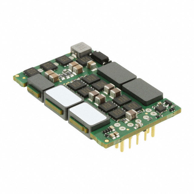
ULS 100-Watt Series www.murata-ps.com Sixteenth-brick DOSA-Compatible, Isolated DC-DC Converters Typical units FEATURES PRODUCT OVERVIEW Industry standard DOSA "Sixteenth-brick" The new ULS 100 Watts series offers output minimum load is required. For systems requiring format and pinout with surface mount option voltages of 3.3Vout (30A), 5Vout (20A), 6.5Vout controlled startup/shutdown, an external remote (15A), and 12Vout (8.3A). The ULS sixteenth-brick On/Off control may use a switch, transistor or 36-75 Volts DC input range, 3.3, 5, 6.5, and series maintains a width of 0.9 inches while still digital logic. Remote Sense inputs compensate for 12 Vdc outputs. retaining up to 100 Watt output and full 2250 Volt resistive line drops at high currents. 2250 Volt Basic input/output isolation DC isolation. The PC-board mount converter fam- Many self-protection features on the ULS series Up to 100 Watts total output power ily accepts 36 to 75 Volts DC inputs and delivers avoid both converter and external circuit hazards. fixed outputs regulated to within ±0.2%. The ULS These include input undervoltage lockout and High efficiency synchronous rectifier topology converters are ideal for datacom and telecom ap- overtemperature shutdown. The output current Stable no-load operation with no required plications, cell phone towers, data centers, server limit uses the “hiccup” autorestart technique (i.e., external components farms and network repeaters. the outputs may be short-circuited indefinitely). ULS outputs may be trimmed within ±10% of Additional features include output overvoltage Operating temperature range -40 to +85°C nominal output while delivering fast settling to protection too. with derating current step loads and no adverse effects from The synchronous rectifier topology yields high Certified to UL 60950-1, CSA-C22.2 No. 234, higher capacitive loads. Excellent ripple and noise efficiency for minimal heat buildup and “no fan” EN60950-1 safety approvals, 2nd Edition specifications assure compatibility to circuits using operation. Extensive self-protection features CPU’s, ASIC’s, programmable logic and FPGA’s. No F1 +Vin (1) Isolation +Vout (8) Barrier • Switching +Sense (7) External • Filters DC On/Off Power Control Controller • Current Sense Source (2) and Power Transfer -Sense (5) Open = On Reference and Closed = Off Error Amplifier (Positive Trim (6) logic) -Vin (3) -Vout (4) Typical topology is shown Figure 1. Simplified Block Diagram For full details go to www.murata-ps.com/rohs www.murata-ps.com/support SDC_ULS-100 Series.B01.D11 Page 1 of 34
ULS 100-Watt Series Sixteenth-brick DOSA-Compatible, Isolated DC-DC Converters PERFORMANCE SPECIFICATIONS SUMMARY AND ORDERING GUIDE Output Input Efficiency Dimensions Root Model Vout Iout Power R/N (mV pk-pk) Regulation (max.) Vin Nom. Range Iin, no load Iin, full (inches) (V) (A, max.) (W) Typ. Max. Line Load (V) (V) (mA) load (A) Min. Typ. ULS-3.3/30-D48 3.3 30 99 70 100 ±0.1% ±0.2% 48 36-75 50 2.27 90% 91% 1.3x0.9x0.4 ULS-5/20-D48 5 20 100 60 120 ±0.125% ±0.125% 48 36-75 50 2.29 89% 91% 1.3x0.9x0.4 ULS-6.5/15-D48 6.5 15 97.5 60 120 ±0.125% ±0.125% 48 36-75 41 2.18 90% 93% 1.3x0.9x0.4 ULS-12/8.3-D48 12 8.3 99.6 80 150 ±0.125% ±0.25% 48 36-75 50 2.26 89% 92% 1.3x0.9x0.4 Please refer to the Part Number Structure when ordering. Regulation specifications describe output voltage deviations from a nominal/midpoint value to either All specifications are typical at nominal line voltage and full load, +25°C unless otherwise noted. extreme (50% load step). See detailed specifications. Output capacitors are 1 μF ceramic multilayer in parallel with 10 μF and a 220µF/100V external input capacitor is needed for the ULS-12/8.3-D48 model. I/O caps are necessary for our test equipment and may not be needed for your application. PART NUMBER STRUCTURE ULS - 3.3 / 30 - D48 N M H Lx - C RoHS Hazardous Substance Compliance (does not claim EU RoHS exemption 7b–lead in solder) C = RoHS-6 Sixteenth Brick Series Pin Length Option (Thru-hole only) Blank = Standard pin length 0.180˝ (4.6mm) L1 = 0.110˝ (2.79mm) ➀ L2 = 0.145˝ (3.68mm) ➀ Nominal Output Voltage: Conformal Coating Option Blank = No coating, standard H = Coating added, optional ➀ (H option is not available on SMT models.) Maximum Rated Output Current Current in Amps SMT Version Option Blank = Through-hole mount Input Voltage Range: M = Surface mount (MSL Rating 3) ➁ D48 = 36-75 Volts (48V nominal) On/Off Control Logic Option N = Negative P = Positive ➀ Special quantity order is required; samples available with standard pin length only. ➁ SMT (M) versions not available in sample quantities. ➂ Some model number combinations may not be available. See website or contact your local Murata sales representative. Simplified Murata-PS logo Product Label Rev As shown in figure 2, because of the small size of these products, t he product labels contain a simplified Murata-PS logo and a character-reduced code to MODEL NAME indicate the model number and manufacturing date code. Not all items on the label are always used. Please note that the label differs from the product Label 1 photograph. Figure 2. Label Artwork Layout REG.-Nr . D216 NOTE: The following models are To Be Discontinued. 0001 Serial # (4 digits) YYWW ULS-3.3/30-D48P-C ULS-5/20-D48P-C ULS-3.3/30-D48PH-C ULS-5/20-D48PH-C Date code ULS-3.3/30-D48PM-C ULS-5/20-D48PM-C Bar code: Data matrix Label 2 www.murata-ps.com/support SDC_ULS-100 Series.B01.D11 Page 2 of 34
ULS 100-Watt Series Sixteenth-brick DOSA-Compatible, Isolated DC-DC Converters FUNCTIONAL SPECIFICATIONS, ULS-3.3/30-D48 ABSOLUTE MAXIMUM RATINGS Conditions ➀ Minimum Typical/Nominal Maximum Units Input Voltage, Continuous 0 80 Vdc Input Voltage, Transient 100 mS max. duration 100 Vdc Isolation Voltage Input to output, continuous 2250 Vdc Input Reverse Polarity None, install external fuse None Vdc On/Off Remote Control Power on, referred to -Vin 0 15 Vdc Output Power 0 99.99 W Current-limited, no damage, short-circuit Output Current 0 30 A protected Storage Temperature Range Vin = Zero (no power) -55 125 °C Absolute maximums are stress ratings. Exposure of devices to greater than any of these conditions may adversely affect long-term reliability. Proper operation under conditions other than those listed in the Performance/Functional Specifications Table is not implied or recommended. INPUT Operating voltage range 36 48 75 Vdc Recommended External Fuse Fast blow 10 A Start-up threshold Rising input voltage 32.5 34.5 35.5 Vdc Undervoltage shutdown Falling input voltage 31 33 34 Vdc Overvoltage shutdown None Vdc Reverse Polarity Protection None, install external fuse None Vdc Internal Filter Type C Input current Full Load Conditions Vin = nominal 2.27 2.31 A Low Line Vin = minimum 3.06 3.12 A Inrush Transient 0.05 A2-Sec. Short Circuit Input Currrent 50 100 mA No Load Iout = minimum, unit = ON 50 150 mA Shut-Down Input Current (Off) 14 18 mA Reflected (back) ripple current ➁ Measured at input with specified filter 20 30 mA, p-p GENERAL and SAFETY Efficiency Vin = 48V, full load 90 91 % Vin = max., full load 89 90 % Isolation Isolation Voltage Input to output, continuous 2250 Vdc Insulation Safety Rating basic Isolation Resistance 100 MΩ Isolation Capacitance 3300 pF Certified to UL-60950-1, CSA-C22.2 No. Safety Yes 60950-1, IEC/EN60950-1, 2nd edition Per Telcordia SR332, issue 1, class 3, ground Calculated MTBF 2.6 Hours x 106 fixed, Tambient = +25°C DYNAMIC CHARACTERISTICS Fixed Switching Frequency 460 480 500 KHz Startup Time Power on to Vout regulated 5 20 mS Startup Time Remote ON to Vout regulated 5 20 mS 50-75-50% load step, settling time to within Dynamic Load Response 10 25 µSec 2% of Vout Dynamic Load Peak Deviation same as above ±75 ±150 mV FEATURES and OPTIONS Remote On/Off Control “N” suffix: Negative Logic, ON state ON = Ground pin or external voltage -0.1 0.8 V Negative Logic, OFF state OFF = Pin open or external voltage 2.5 15 V Control Current Open collector/drain 1 2 mA “P” suffix: Positive Logic, ON state ON = Pin open or external voltage 3.5 15 V Positive Logic, OFF state OFF = Ground pin or external voltage 0 1 V Control Current Open collector/drain 1 2 mA SMT Mounting "M" suffix Sense pins connected externally to respective Remote Sense 10 % Vout pins www.murata-ps.com/support SDC_ULS-100 Series.B01.D11 Page 3 of 34
ULS 100-Watt Series Sixteenth-brick DOSA-Compatible, Isolated DC-DC Converters FUNCTIONAL SPECIFICATIONS, ULS-3.3/30-D48 (CONT.) OUTPUT Conditions ➀ Minimum Typical/Nominal Maximum Units Total Output Power See Derating 98.1 99 99.99 W Voltage Nominal Output Voltage No trim 3.267 3.3 3.333 Vdc Setting Accuracy At 50% load, no trim -1 1 % of Vnom Output Voltage Range User-adjustable -10 10 % of Vnom. Overvoltage Protection Via magnetic feedback 3.9 4.25 4.95 Vdc Current Output Current Range 0 30 30 A Minimum Load Current Limit Inception 98% of Vnom., after warmup 33 37 44 A Short Circuit Hiccup technique, autorecovery within Short Circuit Current 2 5 mA ±1.25% of Vout Short Circuit Duration Output shorted to ground, no damage Continuous (remove short for recovery) Short circuit protection method Current limiting Regulation Line Regulation Vin = min. to max., Vout = nom., Iout = nom. ±0.1 % of Vout Load Regulation Iout = min. to max., Vin = 48V ±0.2 % of Vout Ripple and Noise 5 Hz- 20 MHz BW 70 100 mV pk-pk Temperature Coefficient At all outputs ±0.02 % of Vout./°C Maximum Capacitive Loading Low ESR, resistive load only 4700 μF MECHANICAL (Through Hole Models) Outline Dimensions 1.3X0.9X0.4 Inches (Please refer to outline drawing) LxWxH 33X22.9X10.2 mm Weight 0.56 Ounces 16 Grams Through Hole Pin Diameter 0.04 & 0.06 Inches 1.016X1.524 mm Through Hole Pin Material Copper alloy TH Pin Plating Metal and Thickness Nickel subplate 50 µ-inches Gold overplate 5 µ-inches ENVIRONMENTAL Operating Ambient Temperature Range With Derating -40 85 °C Operating Case Temperature Range No derating -40 120 °C Storage Temperature Vin = Zero (no power) -55 125 °C Thermal Protection/Shutdown Measured in center 115 125 130 °C Electromagnetic Interference External filter is required Conducted, EN55022/CISPR22 B Class Radiated, EN55022/CISPR22 B Class Relative humidity, non-condensing To +85°C 10 90 %RH Altitude must derate -1%/1000 feet -500 10,000 feet -152 3048 meters RoHS rating RoHS-6 www.murata-ps.com/support SDC_ULS-100 Series.B01.D11 Page 4 of 34
ULS 100-Watt Series Sixteenth-brick DOSA-Compatible, Isolated DC-DC Converters Functional Specification Notes ➀ All specifications are typical unless noted. Ambient temperature = ➇ Do not exceed maximum power ratings, Sense limits or output overvoltage +25°Celsius, Vin is nominal, output current is maximum rated nominal. when adjusting output trim values. External output capacitance is 1 µF multilayer ceramic paralleled with ➈ At zero output current, Vout may contain components which slightly 10 µF electrolytic. All caps are low ESR. These capacitors are necessary for exceed the ripple and noise specifications. our test equipment and may not be needed in your application. Testing must be kept short enough that the converter does not appreciably ➉ Output overload protection is non-latching. When the output overload heat up during testing. For extended testing, use plenty of airflow. See is removed, the output will automatically recover. Derating Curves for temperature performance. All models are stable and 11 All models are fully operational and meet published specifications, regulate within spec without external cacacitance. including “cold start” at –40°C. ➁ Input Ripple Current is tested and specified over a 5-20 MHz bandwidth 12 The converter will shut off if the input falls below the undervoltage thresh- and uses a special set of external filters only for the Ripple Current speci- old. It will not restart until the input exceeds the Input Start Up Voltage. fications. Input filtering is Cin = 33 µF, Cbus = 220 µF, Lbus = 12 µH. Use capacitor rated voltages which are twice the maximum expected voltage. 13 Short circuit shutdown begins when the output voltage degrades approxi- mately 2% from the selected setting. Capacitors must accept high speed AC switching currents. 14 Output noise may be further reduced by installing an external filter. See ➂ Note that Maximum Current Derating Curves indicate an average current the Application Notes. Use only as much output filtering as needed and no at nominal input voltage. At higher temperatures and/or lower airflow, the more. Larger caps (especially low-ESR ceramic types) may slow transient converter will tolerate brief full current outputs if the average RMS current response or degrade dynamic performance. Thoroughly test your applica- over time does not exceed the Derating curve. All Derating curves are tion with all components installed. presented at sea level altitude. Be aware of reduced power dissipation with increasing density altitude. 15 To avoid damage or unplanned shutdown, do not sink appreciable reverse output current. ➃ Mean Time Before Failure (MTBF) is calculated using the Telcordia (Belcore) SR-332 Method 1, Case 3, Issue 1, ground fixed conditions. Oper- 16 A fast blow fuse must be installed in series with +Vin to avoid damage to ating temperature = +25°C, full output load, natural air convection. the converter in the event that the source voltage is accidentally applied to the converter with reverse polarity. ➄ The output may be shorted to ground indefinitely with no damage. The Output Short Circuit Current shown in the specifications is an average con- 17 Although extremely unlikely, failure of the internal components of this sisting of very short bursts of full rated current to test whether the output product may expose external application circuits to dangerous voltages, circuit can be repowered. currents, temperatures or power levels. Please thoroughly verify all appli- cations before committing them to service. Be sure to include appropri- ➅ The On/Off Control is normally driven from a switch or relay. An open ately rated FUSES (see specifications and Application Notes) to reduce the collector/open drain transistor may be used in saturation and cut-off risk of failure. (pinch-off) modes. External logic may also be used if voltage levels are fully compliant to the specifications. 18 If Sense is not wired to an external load, connect sense pins to their respective Vout pins. Do not leave sense unconnected. ➆ Regulation specifications describe the deviation as the input line voltage or output load current is varied from a nominal midpoint value to either 19 The switching frequencies of these converters are fixed; see individual extreme (50% load). specifications for model details. www.murata-ps.com/support SDC_ULS-100 Series.B01.D11 Page 5 of 34
ULS 100-Watt Series Sixteenth-brick DOSA-Compatible, Isolated DC-DC Converters TYPICAL PERFORMANCE DATA, ULS-3.3/30-D48 Efficiency and Power Dissipation 96 18 92 16 88 14 84 12 Efficiency (%) 778260 VVVIIINNN === 743586VVV 6810 Loss (Watts) 68 Power Dissipation 4 VIN = 48V 64 2 60 0 2 4 6 8 10 12 14 16 18 20 22 24 26 28 30 Iout (Amps) Maximum Current Temperature Derating at Sea Level Maximum Current Temperature Derating at Sea Level (Vin = 48V, airflow is from Vin- to Vin+) (Vin = 48V, airflow is from Vin to Vout) 32 32 30 30 Amps) 28 0.5 m/s (100 LFM) Amps) 28 Current ( 26 112...050 mmm///sss (((234000000 LLLFFFMMM))) Current ( 26 110...055 mmm///sss (((231000000 LLLFFFMMM))) Output 24 Output 24 2.0 m/s (400 LFM) 22 22 20 20 35 40 45 50 55 60 65 70 75 80 85 35 40 45 50 55 60 65 70 75 80 85 Ambient Temperature (°C) Ambient Temperature (°C) Output Ripple and Noise (Vin=48V, Iout=0A, Ta=+25°C, Vout-ripple=43.3mV) Output Ripple and Noise (Vin=48V, Iout=30A, Ta=+25°C, Vout-ripple=45.6mv) www.murata-ps.com/support SDC_ULS-100 Series.B01.D11 Page 6 of 34
ULS 100-Watt Series Sixteenth-brick DOSA-Compatible, Isolated DC-DC Converters TYPICAL PERFORMANCE DATA, ULS-3.3/30-D48 Enable startup Delay (Vin=48V, Vout=nom, Iout=30A, Cload=4700uF, Startup Delay (Vin=48V, Vout=nom, Iout=30A, Cload=4700uF, Ta=+25°C) Ta=+25°C) Trace2=Vout, Trace4=Enable Trace1=Vin, Trace2=Vout Step Load Transient Response (Vin=48V, Vout=nom, Iout=75% to 50% of full load, Step Load Transient Response (Vin=48V, Vout=nom, Iout=50% to 75% of full load, 1A/uS at Ta=+25°C) +Delta=61mV, Recovery time=8.4uS 1A/uS at Ta=+25°C) +Delta=64mV, Recovery time=7.6uS Step Load Transient Response (Vin=48V, Vout=nom, Iout=50% to 75% of full load, Thermal image with hot spot at full load (30A) current with 30°C ambient; air is flowing at 1A/uS at Ta=+25°C) 100 LFM. Air is flowing across the converter from Vin to Vout at 48V input. Identifiable and recommended maximum value to be verified in application. Hottest spot is Q4=88.9°C. www.murata-ps.com/support SDC_ULS-100 Series.B01.D11 Page 7 of 34
ULS 100-Watt Series Sixteenth-brick DOSA-Compatible, Isolated DC-DC Converters Emissions Performance, Model ULS-3.3/30-D48 Murata Power Solutions measures its products for radio frequency emissions against the EN 55022 and CISPR 22 standards. Passive resistance loads are employed and the output is set to the maximum voltage. If you set up your own emissions testing, make sure the output load is rated at continuous power while doing the tests. The recommended external input and output capacitors (if required) are included. Please refer to the fundamental switching frequency. All of this information is listed in the Product Specifications. An external discrete filter is installed and the circuit diagram is shown below. VCC RTN L1 C1 + + C2 C3 DC/DC C6 Load -48V GND C4 C5 GND Figure 3. Conducted Emissions Test Circuit Graph 1. Conducted emissions performance, Positive Line, CISPR 22, Class A, 48Vin, full load [1]Conducted Emissions Parts List [2]Conducted Emissions Test Equipment Used Hewlett Packard HP8594L Spectrum Analyzer –S/N 3827A00153 2Line V-networks LS1-15V 50Ω/50Uh Line Impedance Stabilization Network [3]Conducted Emissions Test Results Reference Part Number Description Vendor GRM32ER- SMD CERAMIC-100V- C1 Murata 72A105KA01L 1000nF-X7R-1210 SMD CERAMIC GRM- C2 100V-100nF-±10%- Murata 319R72A104KA01D X7R-1206 COMMON MODE- High L1 LB16H1324 1320uH-±25%-4A-R5K- Light 21*21*12.5mm SMD CERAMIC GRM- C4, C5 1000V-0.022uF-±10%- Murata 32DR73A223KW01L X7R-1210 Aluminum 100V-320Uf- C3 UHE2A221MHD Nichicon ±10%-long lead Graph 2. Conducted emissions performance, Negative Line, C6 NA CISPR 22, Class A, 48Vin, full load [4]Layout Recommendations Most applications can use the filtering which is already installed inside the Contact Murata Power Solutions for Class B Emissions test circuit and con- converter or with the addition of the recommended external capacitors. For ducted emissions performance test results. greater emissions suppression, consider additional filter components and/or shielding. Emissions performance will depend on the user’s PC board layout, the chassis shielding environment and choice of external components. Please refer to Application Note GEAN02 for further discussion. Since many factors affect both the amplitude and spectra of emissions, we recommend using an engineer who is experienced at emissions suppression. www.murata-ps.com/support SDC_ULS-100 Series.B01.D11 Page 8 of 34
ULS 100-Watt Series Sixteenth-brick DOSA-Compatible, Isolated DC-DC Converters FUNCTIONAL SPECIFICATIONS, ULS-5/20-D48 ABSOLUTE MAXIMUM RATINGS Conditions ➀ Minimum Typical/Nominal Maximum Units Input Voltage, Continuous 0 80 Vdc Input Voltage, Transient 100 mS max. duration 100 Vdc Isolation Voltage Input to output, continuous 2250 Vdc Input Reverse Polarity None, install external fuse None Vdc On/Off Remote Control Power on, referred to -Vin 0 15 Vdc Output Power 0 101 W Current-limited, no damage, short-circuit Output Current 0 20 A protected Storage Temperature Range Vin = Zero (no power) -55 125 °C Absolute maximums are stress ratings. Exposure of devices to greater than any of these conditions may adversely affect long-term reliability. Proper operation under conditions other than those listed in the Performance/Functional Specifications Table is not implied or recommended. INPUT Operating voltage range 36 48 75 Vdc Recommended External Fuse Fast blow 10 A Start-up threshold Rising input voltage 32.5 34.5 35.5 Vdc Undervoltage shutdown Falling input voltage 31 32.5 34 Vdc Overvoltage shutdown None Vdc Reverse Polarity Protection None, install external fuse None Vdc Internal Filter Type C Input current Full Load Conditions Vin = nominal 2.29 2.36 A Low Line Vin = minimum 3.05 3.15 A Inrush Transient 0.05 A2-Sec. Short Circuit Input Current 50 100 mA No Load Iout = minimum, unit = ON 50 100 mA Shut-Down Input Current (Off) 15 18 mA Reflected (back) ripple current ➁ Measured at input with specified filter 15 30 mA, p-p GENERAL and SAFETY Efficiency Vin = 48V, full load 89 91 % Vin = min., full load 89 91 % Isolation Isolation Voltage Input to output, continuous 2250 Vdc Insulation Safety Rating basic Isolation Resistance 100 MΩ Isolation Capacitance 3300 pF Certified to UL-60950-1, CSA-C22.2 No. Safety Yes 60950-1, IEC/EN60950-1, 2nd edition Per Telcordia SR332, issue 1, class 3, ground Calculated MTBF 2.6 Hours x 106 fixed, Tambient = +25°C DYNAMIC CHARACTERISTICS Fixed Switching Frequency 470 520 570 KHz Startup Time Power on to Vout regulated 15 mS Startup Time Remote ON to Vout regulated 20 mS 50-75-50% load step, settling time to within Dynamic Load Response 10 100 µSec 1% of Vout Dynamic Load Peak Deviation same as above ±180 ±240 mV FEATURES and OPTIONS Remote On/Off Control “N” suffix: Negative Logic, ON state ON = Ground pin or external voltage -0.1 0.8 V Negative Logic, OFF state OFF = Pin open or external voltage 2.5 15 V Control Current Open collector/drain 1 2 mA “P” suffix: Positive Logic, ON state ON = Pin open or external voltage 3.5 15 V Positive Logic, OFF state OFF = Ground pin or external voltage 0 1 V Control Current Open collector/drain 1 2 mA SMT Mounting "M" suffix Sense pins connected externally to respective Remote Sense 10 % Vout pins www.murata-ps.com/support SDC_ULS-100 Series.B01.D11 Page 9 of 34
ULS 100-Watt Series Sixteenth-brick DOSA-Compatible, Isolated DC-DC Converters FUNCTIONAL SPECIFICATIONS, ULS-5/20-D48 (CONT.) OUTPUT Conditions ➀ Minimum Typical/Nominal Maximum Units Total Output Power See Derating 99 100 101 W Voltage Nominal Output Voltage No trim 4.95 5 505 Vdc Setting Accuracy At 50% load, no trim -1 1 % of Vnom Output Voltage Range User-adjustable -10 10 % of Vnom. Overvoltage Protection Via magnetic feedback 5.6 6.3 9 Vdc Current Output Current Range 0 20 20 A Minimum Load Current Limit Inception 98% of Vnom., after warmup 22 24 32 A Short Circuit Hiccup technique, autorecovery within Short Circuit Current .6 A ±1.25% of Vout Short Circuit Duration Output shorted to ground, no damage Continuous (remove short for recovery) Short circuit protection method Current limiting Regulation Line Regulation Vin = min. to max., Vout = nom., Iout = nom. ±0.125 % of Vout Load Regulation Iout = min. to max., Vin = 48V ±0.125 % of Vout Ripple and Noise 5 Hz- 20 MHz BW 60 120 mV pk-pk Temperature Coefficient At all outputs ±0.02 % of Vout./°C Maximum Capacitive Loading Low ESR, resistive load only 330 3300 μF MECHANICAL (Through Hole Models) Outline Dimensions 1.3X0.9X0.4 Inches (Please refer to outline drawing) LxWxH 33X22.9X10.2 mm Weight 0.58 Ounces 16.5 Grams Through Hole Pin Diameter 0.04 & 0.06 Inches 1.016X1.524 mm Through Hole Pin Material Copper alloy TH Pin Plating Metal and Thickness Nickel subplate 50 µ-inches Gold overplate 5 µ-inches ENVIRONMENTAL Operating Ambient Temperature Range With Derating -40 85 °C Operating Case Temperature Range No derating -40 120 °C Storage Temperature Vin = Zero (no power) -55 125 °C Thermal Protection/Shutdown Measured in center 115 125 130 °C Electromagnetic Interference External filter is required Conducted, EN55022/CISPR22 B Class Radiated, EN55022/CISPR22 B Class RoHS rating RoHS-6 www.murata-ps.com/support SDC_ULS-100 Series.B01.D11 Page 10 of 34
ULS 100-Watt Series Sixteenth-brick DOSA-Compatible, Isolated DC-DC Converters TYPICAL PERFORMANCE DATA, ULS-5/20-D48 Efficiency and Power Dissipation 94 22 92 20 90 18 88 16 86 VIN = 75V 14 Efficiency (%) 888024 VVIINN == 4386VV 81102 Loss (Watts) 78 6 Power Dissipation 76 VIN = 48V 4 74 2 72 0 2 4 6 8 10 12 14 16 18 20 Iout (Amps) Maximum Current Temperature Derating at Sea Level Maximum Current Temperature Derating at Sea Level (Vin = 48V, airflow is from Vin- to Vin+) (Vin = 48V, airflow is from Vin to Vout) 21 21 20 20 19 19 Current (Amps) 111678 0110....20555 mmm m///sss/ s((( 231(50000000 LLLLFFFFMMMM)))) Current (Amps) 111678 010...2055 mm m//ss/ s(( 21(500000 LLLFFFMMM))) Output 15 2.0 m/s (400 LFM) Output 15 12..50 mm//ss ((340000 LLFFMM)) 14 14 13 13 12 12 30 35 40 45 50 55 60 65 70 75 80 85 30 35 40 45 50 55 60 65 70 75 80 85 Ambient Temperature (°C) Ambient Temperature (°C) Output Ripple and noise (Vin = 48V, Vout = nom, Iout = 20A, Cload = 330uf, Ta = +25°C) Output Ripple and noise (Vin = 48V, Vout = nom, Iout = 0A, Cload = 330uF, Ta = +25°C) www.murata-ps.com/support SDC_ULS-100 Series.B01.D11 Page 11 of 34
ULS 100-Watt Series Sixteenth-brick DOSA-Compatible, Isolated DC-DC Converters TYPICAL PERFORMANCE DATA, ULS-5/20-D48 Enable Startup Delay (Vin = 48V, Vout = nom, Iout = 20A, Cload = 330uF, Ta = +25°C) Vin Startup Delay (Vin = 48V, Vout = nom, Iout = 20A, Cload = 330uF, Ta = +25°C) Ch2 = Vout, Ch4 = Enable. Ch1 = Vin, Ch2 = Vout. Step Load Transient Response (Vin = 48V, Vout = nom, Iout = 75%-50% Step Load Transient Response (Vin = 48V, Vout = nom, Iout = 50%-75% of full load, Ta = +25°C) of full load, Ta = +25°C) Step Load Transient Response (Vin = 48V, Vout = nom, Iout = 50%-75%-50% Thermal image with hot spot at full load (20A) current with 30°C ambient; air is flowing at of full load, Ta = +25°C) 100 LFM. Air is flowing across the converter from Vin to Vout at 48V input. Identifiable and recommended maximum value to be verified in application. Hottest spot is Q4 = 103.4°C. www.murata-ps.com/support SDC_ULS-100 Series.B01.D11 Page 12 of 34
ULS 100-Watt Series Sixteenth-brick DOSA-Compatible, Isolated DC-DC Converters Emissions Performance, Model ULS-5/20-D48 Murata Power Solutions measures its products for radio frequency emissions against the EN 55022 and CISPR 22 standards. Passive resistance loads are employed and the output is set to the maximum voltage. If you set up your own emissions testing, make sure the output load is rated at continuous power while doing the tests. The recommended external input and output capacitors (if required) are included. Please refer to the fundamental switching frequency. All of this information is listed in the Product Specifications. An external discrete filter is installed and the circuit diagram is shown below. VCC RTN L1 C1 + + C2 C3 DC/DC C6 Load -48V GND C4 C5 GND Figure 4. Conducted Emissions Test Circuit Graph 3. Conducted emissions performance, Positive Line, CISPR 22, Class A, 48Vin, full load [1]Conducted Emissions Parts List [2]Conducted Emissions Test Equipment Used Hewlett Packard HP8594L Spectrum Analyzer –S/N 3827A00153 2Line V-networks LS1-15V 50Ω/50Uh Line Impedance Stabilization Network [3]Conducted Emissions Test Results Reference Part Number Description Vendor GRM32ER- SMD CERAMIC-100V- C1 Murata 72A105KA01L 1000nF-X7R-1210 SMD CERAMIC GRM- C2 100V-100nF-±10%- Murata 319R72A104KA01D X7R-1206 COMMON MODE- High L1 LB16H1324 1320uH-±25%-4A-R5K- Light 21*21*12.5mm SMD CERAMIC GRM- C4, C5 1000V-0.022uF-±10%- Murata 32DR73A223KW01L X7R-1210 Aluminum 100V-320Uf- C3 UHE2A221MHD Nichicon ±10%-long lead Graph 4. Conducted emissions performance, Negative Line, C6 NA CISPR 22, Class A, 48Vin, full load [4]Layout Recommendations Most applications can use the filtering which is already installed inside the Contact Murata Power Solutions for Class B Emissions test circuit and con- converter or with the addition of the recommended external capacitors. For ducted emissions performance test results. greater emissions suppression, consider additional filter components and/or shielding. Emissions performance will depend on the user’s PC board layout, the chassis shielding environment and choice of external components. Please refer to Application Note GEAN02 for further discussion. Since many factors affect both the amplitude and spectra of emissions, we recommend using an engineer who is experienced at emissions suppression. www.murata-ps.com/support SDC_ULS-100 Series.B01.D11 Page 13 of 34
ULS 100-Watt Series Sixteenth-brick DOSA-Compatible, Isolated DC-DC Converters FUNCTIONAL SPECIFICATIONS, ULS-6.5/15-D48 ABSOLUTE MAXIMUM RATINGS Conditions ➀ Minimum Typical/Nominal Maximum Units Input Voltage, Continuous 0 80 Vdc Input Voltage, Transient 100 mS max. duration 100 Vdc Isolation Voltage Input to output, continuous 2250 Vdc Input Reverse Polarity None, install external fuse None Vdc On/Off Remote Control Power on, referred to -Vin 0 15 Vdc Output Power 0 98.48 W Current-limited, no damage, short-circuit Output Current 0 15 A protected Storage Temperature Range Vin = Zero (no power) -55 125 °C Absolute maximums are stress ratings. Exposure of devices to greater than any of these conditions may adversely affect long-term reliability. Proper operation under conditions other than those listed in the Performance/Functional Specifications Table is not implied or recommended. INPUT Operating voltage range 36 48 75 Vdc Recommended External Fuse Fast blow 10 A Start-up threshold Rising input voltage 32.5 34.5 35.5 Vdc Undervoltage shutdown Falling input voltage 31 32.5 34 Vdc Overvoltage shutdown None Vdc Reverse Polarity Protection None, install external fuse None Vdc Internal Filter Type C Input current Full Load Conditions Vin = nominal 2.18 2.28 A Low Line Vin = minimum 2.91 3.05 A Inrush Transient 0.05 A2-Sec. Short Circuit Input Current 50 100 mA No Load Iout = minimum, unit = ON 41 100 mA Shut-Down Input Current (Off) 5 10 mA Reflected (back) ripple current ➁ Measured at input with specified filter 15 30 mA, p-p GENERAL and SAFETY Efficiency Vin = 48V, full load 90 93 % Vin = min., full load 90 93 % Isolation Isolation Voltage Input to output, continuous 2250 Vdc Insulation Safety Rating basic Isolation Resistance 100 MΩ Isolation Capacitance 3300 pF Certified to UL-60950-1, CSA-C22.2 No. Safety Yes 60950-1, IEC/EN60950-1, 2nd edition Per Telcordia SR332, issue 1, class 3, ground Calculated MTBF 2.6 Hours x 106 fixed, Tambient = +25°C DYNAMIC CHARACTERISTICS Fixed Switching Frequency 250 KHz Startup Time Power on to Vout regulated 30 mS Startup Time Remote ON to Vout regulated 30 mS 50-60-50% load step, settling time to within Dynamic Load Response 100 µSec 1% of Vout Dynamic Load Peak Deviation same as above ±55 mV FEATURES and OPTIONS Remote On/Off Control “N” suffix: Negative Logic, ON state ON = Ground pin or external voltage -0.1 0.8 V Negative Logic, OFF state OFF = Pin open or external voltage 2.5 15 V Control Current Open collector/drain 1 2 mA “P” suffix: Positive Logic, ON state ON = Pin open or external voltage 3.5 15 V Positive Logic, OFF state OFF = Ground pin or external voltage 0 1 V Control Current Open collector/drain 1 2 mA SMT Mounting "M" suffix Sense pins connected externally to respective Remote Sense 10 % Vout pins www.murata-ps.com/support SDC_ULS-100 Series.B01.D11 Page 14 of 34
ULS 100-Watt Series Sixteenth-brick DOSA-Compatible, Isolated DC-DC Converters FUNCTIONAL SPECIFICATIONS, ULS-6.5/15-D48 (CONT.) OUTPUT Conditions ➀ Minimum Typical/Nominal Maximum Units Total Output Power See Derating 0 97.5 98.48 W Voltage Nominal Output Voltage No trim 6.435 6.5 6.565 Vdc Setting Accuracy At 50% load, no trim -1 1 % of Vnom Output Voltage Range User-adjustable -10 10 % of Vnom. Overvoltage Protection Via magnetic feedback 7.4 8.5 10 Vdc Current Output Current Range 0 15 15 A Minimum Load Current Limit Inception 98% of Vnom., after warmup 18 22 25 A Short Circuit Hiccup technique, autorecovery within Short Circuit Current .6 A ±1.25% of Vout Short Circuit Duration Output shorted to ground, no damage Continuous (remove short for recovery) Short circuit protection method Current limiting Regulation Line Regulation Vin = min. to max., Vout = nom., Iout = nom. ±0.125 % of Vout Load Regulation Iout = min. to max., Vin = 48V ±0.125 % of Vout Ripple and Noise 5 Hz- 20 MHz BW 60 120 mV pk-pk Temperature Coefficient At all outputs ±0.02 % of Vout./°C Maximum Capacitive Loading Low ESR, resistive load only 330 3300 μF MECHANICAL (Through Hole Models) Outline Dimensions 1.3x0.9x0.4 Inches (Please refer to outline drawing) LxWxH 33x22.9x10.2 mm Weight 0.58 Ounces 16.5 Grams Through Hole Pin Diameter 0.04 & 0.06 Inches 1.016x1.524 mm Through Hole Pin Material Copper alloy TH Pin Plating Metal and Thickness Nickel subplate 50 µ-inches Gold overplate 5 µ-inches ENVIRONMENTAL Operating Ambient Temperature Range With Derating -40 85 °C Operating Case Temperature Range No derating -40 120 °C Storage Temperature Vin = Zero (no power) -55 125 °C Thermal Protection/Shutdown Measured in center 115 125 130 °C Electromagnetic Interference External filter is required Conducted, EN55022/CISPR22 B Class Radiated, EN55022/CISPR22 B Class RoHS rating RoHS-6 www.murata-ps.com/support SDC_ULS-100 Series.B01.D11 Page 15 of 34
ULS 100-Watt Series Sixteenth-brick DOSA-Compatible, Isolated DC-DC Converters Functional Specification Notes ➀ All specifications are typical unless noted. Ambient temperature = ➇ Do not exceed maximum power ratings, Sense limits or output overvoltage +25°Celsius, Vin is nominal, output current is maximum rated nominal. when adjusting output trim values. External output capacitance is 1 µF multilayer ceramic paralleled with ➈ At zero output current, Vout may contain components which slightly 10 µF electrolytic. All caps are low ESR. These capacitors are necessary for exceed the ripple and noise specifications. our test equipment and may not be needed in your application. Testing must be kept short enough that the converter does not appreciably ➉ Output overload protection is non-latching. When the output overload heat up during testing. For extended testing, use plenty of airflow. See is removed, the output will automatically recover. Derating Curves for temperature performance. All models are stable and 11 All models are fully operational and meet published specifications, regulate within spec without external cacacitance. including “cold start” at –40°C. ➁ Input Ripple Current is tested and specified over a 5-20 MHz bandwidth 12 The converter will shut off if the input falls below the undervoltage thresh- and uses a special set of external filters only for the Ripple Current speci- old. It will not restart until the input exceeds the Input Start Up Voltage. fications. Input filtering is Cin = 33 µF, Cbus = 220 µF, Lbus = 12 µH. Use capacitor rated voltages which are twice the maximum expected voltage. 13 Short circuit shutdown begins when the output voltage degrades approxi- mately 2% from the selected setting. Capacitors must accept high speed AC switching currents. 14 Output noise may be further reduced by installing an external filter. See ➂ Note that Maximum Current Derating Curves indicate an average current the Application Notes. Use only as much output filtering as needed and no at nominal input voltage. At higher temperatures and/or lower airflow, the more. Larger caps (especially low-ESR ceramic types) may slow transient converter will tolerate brief full current outputs if the average RMS current response or degrade dynamic performance. Thoroughly test your applica- over time does not exceed the Derating curve. All Derating curves are tion with all components installed. presented at sea level altitude. Be aware of reduced power dissipation with increasing density altitude. 15 To avoid damage or unplanned shutdown, do not sink appreciable reverse output current. ➃ Mean Time Before Failure (MTBF) is calculated using the Telcordia (Belcore) SR-332 Method 1, Case 3, Issue 1, ground fixed conditions. Oper- 16 A fast blow fuse must be installed in series with +Vin to avoid damage to ating temperature = +25°C, full output load, natural air convection. the converter in the event that the source voltage is accidentally applied to the converter with reverse polarity. ➄ The output may be shorted to ground indefinitely with no damage. The Output Short Circuit Current shown in the specifications is an average con- 17 Although extremely unlikely, failure of the internal components of this sisting of very short bursts of full rated current to test whether the output product may expose external application circuits to dangerous voltages, circuit can be repowered. currents, temperatures or power levels. Please thoroughly verify all appli- cations before committing them to service. Be sure to include appropri- ➅ The On/Off Control is normally driven from a switch or relay. An open ately rated FUSES (see specifications and Application Notes) to reduce the collector/open drain transistor may be used in saturation and cut-off risk of failure. (pinch-off) modes. External logic may also be used if voltage levels are fully compliant to the specifications. 18 If Sense is not wired to an external load, connect sense pins to their respective Vout pins. Do not leave sense unconnected. ➆ Regulation specifications describe the deviation as the input line voltage or output load current is varied from a nominal midpoint value to either 19 The switching frequencies of these converters are fixed; see individual extreme (50% load). specifications for model details. www.murata-ps.com/support SDC_ULS-100 Series.B01.D11 Page 16 of 34
ULS 100-Watt Series Sixteenth-brick DOSA-Compatible, Isolated DC-DC Converters TYPICAL PERFORMANCE DATA, ULS-6.5/15-D48 Efficiency and Power Dissipation 100 18 95 16 90 Vin = 36V 14 85 Vin = 48V 12 %) 80 Efficiency ( 677505 VP(Vioninw = e= r7 4D58iVsVs)ipation 6810 Loss (Watts) 60 4 55 2 50 0 0 2 4 6 8 10 12 14 16 Iout (Amps) Maximum Current Temperature Derating at Sea Level Maximum Current Temperature Derating at Sea Level (Vin = 48V, airflow is from Vin- to Vin+) (Vin = 48V, airflow is from Vin to Vout) 16 16 15 15 mps) 14 32..05mm//ss((650000LLFFMM)) mps) 14 32..05mm//ss((650000LLFFMM)) Output Current (A 1123 2110....0505mmmm////ssss((((432100000000LLLLFFFFMMMM)))) Output Current (A 1123 2110....0505mmmm////ssss((((432100000000LLLLFFFFMMMM)))) 11 11 10 10 35 40 45 50 55 60 65 70 75 80 85 35 40 45 50 55 60 65 70 75 80 85 Ambient Temperature (ºC) Ambient Temperature (ºC) Output ripple and Noise (Vin=48V, Iout=0, Ta=+25°C) Output ripple and Noise (Vin=48V, Iout=15A, Ta=+25°C) Vout ripple=17.5mV Vout ripple=23.8mV www.murata-ps.com/support SDC_ULS-100 Series.B01.D11 Page 17 of 34
ULS 100-Watt Series Sixteenth-brick DOSA-Compatible, Isolated DC-DC Converters TYPICAL PERFORMANCE DATA, ULS-6.5/15-D48 Enable Startup Delay (Vin=48V, Iout=15A, Cload=3300uf, Ta=+25°C) Trace 2=Vout, Startup Delay (Vin=48V, Iout=15A, Cload=3300uF, Ta=+25°C) Trace 1=Vin, Trace 4=Enable Trace 2=Vout Step Load Transient Response (Vin=48V, Vout=nom, Iout= 75% to 50% of full load, Step Load Transient Response (Vin=48V, Vout=nom, Iout= 50% to 75% of full load, 1A/uS at Ta=+25°C) +Delta=67mV, Rocovery time=0uS 1A/uS at Ta=+25°C) +Delta=80mV, Rocovery time=10uS Step Load Transient Response (Vin=48V, Vout=nom, Iout= 50% to 75% of full load, 1A/uS at Ta=+25°C) www.murata-ps.com/support SDC_ULS-100 Series.B01.D11 Page 18 of 34
ULS 100-Watt Series Sixteenth-brick DOSA-Compatible, Isolated DC-DC Converters Emissions Performance, Model ULS-6.5/15-D48 [3]Conducted Emissions Test Results Murata Power Solutions measures its products for radio frequency emissions against the EN 55022 and CISPR 22 standards. Passive resistance loads are employed and the output is set to the maximum voltage. If you set up your own emissions testing, make sure the output load is rated at continuous power while doing the tests. The recommended external input and output capacitors (if required) are included. Please refer to the fundamental switching frequency. All of this information is listed in the Product Specifications. An external discrete filter is installed and the circuit diagram is shown below. RTN VCC L1 L2 C1C2 C3 C4C5 + + C6C7 DC/DC C12 LOAD -48V C8 C9 C10 C11 GND Graph 5. Conducted emissions performance, Positive Line, CISPR 22, Class A, 48Vin, full load GND Figure 5. Conducted Emissions Test Circuit [1]Conducted Emissions Parts List Reference Part Number Description Vendor C1, C2, C3, C4, GRM32ER72A105KA01L SMD CERAMIC-100V-1000nF-X7R-1210 Murata C5 SMD CERAMIC100V-100nF-±10%- C6 GRM319R72A104KA01D Murata X7R-1206 L1, L2 PG0060T COMMON MODE-473uH-±25%-14A Pulse C8, C9, SMD CERAMIC 630V-0.22uF-±10%- GRM55DR72J224KW01L Murata C10, C11 X7R-2220 C7 UHE2A221MHD Aluminum100V-220Uf-±10%-long lead Nichicon C12 NA [2]Conducted Emissions Test Equipment Used Hewlett Packard HP8594L Spectrum Analyzer –S/N 3827A00153 Graph 6. Conducted emissions performance, Negative Line, CISPR 22, Class A, 48Vin, full load 2Line V-networks LS1-15V 50Ω /50Uh Line Impedance Stabilization Network [3]Layout Recommendations Most applications can use the filtering which is already installed inside the converter or with the addition of the recommended external capacitors. For greater emissions suppression, consider additional filter components and/or shielding. Emissions performance will depend on the user’s PC board layout, the chassis shielding environment and choice of external components. Please refer to Application Note GEAN-02 for further discussion. Since many factors affect both the amplitude and spectra of emissions, we recommend using an engineer who is experienced at emissions suppression. www.murata-ps.com/support SDC_ULS-100 Series.B01.D11 Page 19 of 34
ULS 100-Watt Series Sixteenth-brick DOSA-Compatible, Isolated DC-DC Converters FUNCTIONAL SPECIFICATIONS, ULS-12/8.3-D48 ABSOLUTE MAXIMUM RATINGS Conditions ➀ Minimum Typical/Nominal Maximum Units Input Voltage, Continuous 0 80 Vdc Input Voltage, Transient 100 mS max. duration 100 Vdc Isolation Voltage Input to output, continuous 2250 Vdc Input Reverse Polarity None, install external fuse None Vdc On/Off Remote Control Power on, referred to -Vin 0 15 Vdc Output Power 0 100.6 W Current-limited, no damage, short-circuit Output Current 0 8.3 A protected Storage Temperature Range Vin = Zero (no power) -55 125 °C Absolute maximums are stress ratings. Exposure of devices to greater than any of these conditions may adversely affect long-term reliability. Proper operation under conditions other than those listed in the Performance/Functional Specifications Table is not implied or recommended. INPUT Operating voltage range 36 48 75 Vdc Recommended External Fuse Fast blow 10 A Start-up threshold Rising input voltage 32.5 34.5 35.5 Vdc Undervoltage shutdown Falling input voltage 31 32.5 34 Vdc Overvoltage shutdown None Vdc Reverse Polarity Protection None, install external fuse None Vdc Internal Filter Type C Input current Full Load Conditions Vin = nominal 2.26 2.35 A Low Line Vin = minimum 3.01 3.14 A Inrush Transient 0.05 A2-Sec. Short Circuit Input Current .1 100 mA No Load Input Current Iout = minimum, unit = ON 50 150 mA Shut-Down Input Current (Off) 5 10 mA Reflected (back) ripple current ➁ Measured at input with specified filter 15 30 mA, p-p GENERAL and SAFETY Efficiency Vin = 48V, full load 89 92 % Vin = min., full load 89 92 % Isolation Isolation Voltage Input to output, continuous 2250 Vdc Insulation Safety Rating basic Isolation Resistance 100 MΩ Isolation Capacitance 3300 pF Certified to UL-60950-1, CSA-C22.2 No. Safety Yes 60950-1, IEC/EN60950-1, 2nd edition Per Telcordia SR332, issue 1, class 3, ground Calculated MTBF 2.6 Hours x 106 fixed, Tambient = +25°C DYNAMIC CHARACTERISTICS Fixed Switching Frequency 470 520 570 KHz Startup Time Power on to Vout regulated 20 mS Startup Time Remote ON to Vout regulated 20 mS 50-75-50% load step, settling time to within Dynamic Load Response 100 µSec 1% of Vout Dynamic Load Peak Deviation same as above ±180 ±240 mV FEATURES and OPTIONS Remote On/Off Control “N” suffix: Negative Logic, ON state ON = Ground pin or external voltage -0.1 0.8 V Negative Logic, OFF state OFF = Pin open or external voltage 2.5 15 V Control Current Open collector/drain 1 2 mA “P” suffix: Positive Logic, ON state ON = Pin open or external voltage 3.5 15 V Positive Logic, OFF state OFF = Ground pin or external voltage 0 1 V Control Current Open collector/drain 1 2 mA SMT Mounting "M" suffix Sense pins connected externally to respective Remote Sense 10 % Vout pins www.murata-ps.com/support SDC_ULS-100 Series.B01.D11 Page 20 of 34
ULS 100-Watt Series Sixteenth-brick DOSA-Compatible, Isolated DC-DC Converters FUNCTIONAL SPECIFICATIONS, ULS-12/8.3-D48 (CONT.) OUTPUT Conditions ➀ Minimum Typical/Nominal Maximum Units Total Output Power See Derating 98.6 99.6 100.6 W Voltage Nominal Output Voltage No trim 11.88 12 12.12 Vdc Setting Accuracy At 50% load, no trim -1 1 % of Vnom Output Voltage Range User-adjustable -10 10 % of Vnom. Overvoltage Protection Via magnetic feedback, static OVP 13.8 14.5 15.8 Vdc Current Output Current Range 0 8.3 8.3 A Minimum Load Current Limit Inception 98% of Vnom., after warmup 9 10.5 12.5 A Short Circuit Hiccup technique, autorecovery within Short Circuit Current 0.6 A ±1.25% of Vout Short Circuit Duration Output shorted to ground, no damage Continuous (remove short for recovery) Short circuit protection method Current limiting Regulation Line Regulation Vin = min. to max., Vout = nom., Iout = nom. ±0.125 % of Vout Load Regulation Iout = min. to max., Vin = 48V ±0.25 % of Vout Ripple and Noise 5 Hz- 20 MHz BW 80 150 mV pk-pk Temperature Coefficient At all outputs ±0.02 % of Vout./°C Maximum Capacitive Loading Low ESR, resistive load only 220 3300 μF MECHANICAL (Through Hole Models) Outline Dimensions 1.3X0.9X0.4 Inches (Please refer to outline drawing) LxWxH 33X22.9X10.2 mm Weight 0.56 Ounces 16 Grams Through Hole Pin Diameter 0.04 & 0.06 Inches 1.016X1.524 mm Through Hole Pin Material Copper alloy TH Pin Plating Metal and Thickness Nickel subplate 50 µ-inches Gold overplate 5 µ-inches ENVIRONMENTAL Operating Ambient Temperature Range With Derating -40 85 °C Operating Case Temperature Range No derating -40 120 °C Storage Temperature Vin = Zero (no power) -55 125 °C Thermal Protection/Shutdown Measured in center 115 125 130 °C Electromagnetic Interference External filter is required Conducted, EN55022/CISPR22 B Class Radiated, EN55022/CISPR22 B Class Relative humidity, non-condensing To +85°C 10 90 %RH Altitude must derate -1%/1000 feet -500 10,000 feet -152 3048 meters RoHS rating RoHS-6 www.murata-ps.com/support SDC_ULS-100 Series.B01.D11 Page 21 of 34
ULS 100-Watt Series Sixteenth-brick DOSA-Compatible, Isolated DC-DC Converters Functional Specification Notes ➀ All specifications are typical unless noted. Ambient temperature = ➇ Do not exceed maximum power ratings, Sense limits or output overvoltage +25°Celsius, Vin is nominal, output current is maximum rated nominal. when adjusting output trim values. External output capacitance is 1 µF multilayer ceramic paralleled with ➈ At zero output current, Vout may contain components which slightly 10 µF electrolytic. All caps are low ESR. These capacitors are necessary for exceed the ripple and noise specifications. our test equipment and may not be needed in your application. Testing must be kept short enough that the converter does not appreciably ➉ Output overload protection is non-latching. When the output overload heat up during testing. For extended testing, use plenty of airflow. See is removed, the output will automatically recover. Derating Curves for temperature performance. All models are stable and 11 All models are fully operational and meet published specifications, regulate within spec without external cacacitance. including “cold start” at –40°C. ➁ Input Ripple Current is tested and specified over a 5-20 MHz bandwidth 12 The converter will shut off if the input falls below the undervoltage thresh- and uses a special set of external filters only for the Ripple Current speci- old. It will not restart until the input exceeds the Input Start Up Voltage. fications. Input filtering is Cin = 33 µF, Cbus = 220 µF, Lbus = 12 µH. Use capacitor rated voltages which are twice the maximum expected voltage. 13 Short circuit shutdown begins when the output voltage degrades approxi- mately 2% from the selected setting. Capacitors must accept high speed AC switching currents. 14 Output noise may be further reduced by installing an external filter. See ➂ Note that Maximum Current Derating Curves indicate an average current the Application Notes. Use only as much output filtering as needed and no at nominal input voltage. At higher temperatures and/or lower airflow, the more. Larger caps (especially low-ESR ceramic types) may slow transient converter will tolerate brief full current outputs if the average RMS current response or degrade dynamic performance. Thoroughly test your applica- over time does not exceed the Derating curve. All Derating curves are tion with all components installed. presented at sea level altitude. Be aware of reduced power dissipation with increasing density altitude. 15 To avoid damage or unplanned shutdown, do not sink appreciable reverse output current. ➃ Mean Time Before Failure (MTBF) is calculated using the Telcordia (Belcore) SR-332 Method 1, Case 3, Issue 1, ground fixed conditions. Oper- 16 A fast blow fuse must be installed in series with +Vin to avoid damage to ating temperature = +25°C, full output load, natural air convection. the converter in the event that the source voltage is accidentally applied to the converter with reverse polarity. ➄ The output may be shorted to ground indefinitely with no damage. The Output Short Circuit Current shown in the specifications is an average con- 17 Although extremely unlikely, failure of the internal components of this sisting of very short bursts of full rated current to test whether the output product may expose external application circuits to dangerous voltages, circuit can be repowered. currents, temperatures or power levels. Please thoroughly verify all appli- cations before committing them to service. Be sure to include appropri- ➅ The On/Off Control is normally driven from a switch or relay. An open ately rated FUSES (see specifications and Application Notes) to reduce the collector/open drain transistor may be used in saturation and cut-off risk of failure. (pinch-off) modes. External logic may also be used if voltage levels are fully compliant to the specifications. 18 If Sense is not wired to an external load, connect sense pins to their respective Vout pins. Do not leave sense unconnected. ➆ Regulation specifications describe the deviation as the input line voltage or output load current is varied from a nominal midpoint value to either 19 The switching frequencies of these converters are fixed; see individual extreme (50% load). specifications for model details. www.murata-ps.com/support SDC_ULS-100 Series.B01.D11 Page 22 of 34
ULS 100-Watt Series Sixteenth-brick DOSA-Compatible, Isolated DC-DC Converters TYPICAL PERFORMANCE DATA, ULS-12/8.3-D48 Efficiency and Power Dissipation 96 18 92 16 88 14 84 12 VIN = 75V Efficiency (%) 778260 VVIINN == 4386VV 6810 Loss (Watts) 68 4 Power Dissipation 64 VIN = 48V 2 60 0 0.83 1.66 2.49 3.32 4.15 4.98 5.81 6.64 7.47 8.3 Iout (Amps) Maximum Current Temperature Derating at Sea Level Maximum Current Temperature Derating at Sea Level (Vin = 48V, airflow is from Vin- to Vin+) (Vin = 48V, airflow is from Vin to Vout) 8.8 8.8 8.3 8.3 7.8 0.25 m/s (50 LFM) 7.8 0.25 m/s (50 LFM) mps) 10..05 mm//ss ((210000 LLFFMM)) mps) 10..05 mm//ss ((210000 LLFFMM)) Current (A 67..83 12..50 mm//ss ((340000 LLFFMM)) Current (A 67..83 12..50 mm//ss ((340000 LLFFMM)) Output 6.3 Output 6.3 5.8 5.8 5.3 5.3 30 35 40 45 50 55 60 65 70 75 80 85 30 35 40 45 50 55 60 65 70 75 80 85 Ambient Temperature (°C) Ambient Temperature (°C) Output ripple and Noise (Vin=48V, Iout=0, Cload= 1uf || 10uF, Ta=+25°C) Output ripple and Noise (Vin=48V, Iout=8.3A, Cload= 1uf || 10uF, Ta=+25°C) Vout ripple=61mV Vout ripple=66mV www.murata-ps.com/support SDC_ULS-100 Series.B01.D11 Page 23 of 34
ULS 100-Watt Series Sixteenth-brick DOSA-Compatible, Isolated DC-DC Converters TYPICAL PERFORMANCE DATA, ULS-12/8.3-D48 Enable Startup Delay (Vin=48V, Iout=8.3A, Cload=3300uf, Ta=+25°C) Trace 2=Vout, Startup Delay (Vin=48V, Iout=8.3A, Cload=3300uF, Ta=+25°C) Trace 1=Vin, Trace 4=Enable Trace 2=Vout Step Load Transient Response (Vin=48V, Vout=nom, Iout= 75% to 50% of full load, Step Load Transient Response (Vin=48V, Vout=nom, Iout= 50% to 75% of full load, 1A/uS at Ta=+25°C) +Delta=166mV, Rocovery time=11.8uS 1A/uS at Ta=+25°C) +Delta=172mV, Rocovery time=12uS Step Load Transient Response (Vin=48V, Vout=nom, Iout= 50% to 75% of full load, Thermal image with hot spot at full load current (8.3A) with 30°C ambient; air is flowing at 1A/uS at Ta=+25°C) 100 LFM. Air is flowing across the converter from Vin to Vout at 48V input. Identifiable and recommended maximum value to be verified in application. Hottest spot is Q4=86.2°C. www.murata-ps.com/support SDC_ULS-100 Series.B01.D11 Page 24 of 34
ULS 100-Watt Series Sixteenth-brick DOSA-Compatible, Isolated DC-DC Converters Emissions Performance, Model ULS-12/8.3-D48 [3]Conducted Emissions Test Results Murata Power Solutions measures its products for radio frequency emissions against the EN 55022 and CISPR 22 standards. Passive resistance loads are employed and the output is set to the maximum voltage. If you set up your own emissions testing, make sure the output load is rated at continuous power while doing the tests. The recommended external input and output capacitors (if required) are included. Please refer to the fundamental switching frequency. All of this information is listed in the Product Specifications. An external discrete filter is installed and the circuit diagram is shown below. VCC RTN L1 + + C1 C2 C3 C6 LOAD DC/DC -48V C4 C5 GND Graph 5. Conducted emissions performance, Positive Line, CISPR 22, Class A, 48Vin, full load GND Figure 5. Conducted Emissions Test Circuit [1]Conducted Emissions Parts List Reference Part Number Description Vendor SMD CERAMIC C1 GRM32ER72A105KA01L Murata 100V-1000nF-X7R-1210 SMD CERAMIC C2 GRM319R72A104KA01D Murata 100V-100nF-±10%-X7R-1206 COMMON MODE High L1 LB16H1324 1320uH-±25%-4A-R5K-21 *21*12.5mm Light SMD CERAMIC C4, C5 GRM32DR73A223KW01L Murata 1000V-0.022uF-±10%-X7R-1210 Aluminum C3 UHE2A221MHD Nichicon 100V-320Uf-±10%-long lead C6 NA [2]Conducted Emissions Test Equipment Used Hewlett Packard HP8594L Spectrum Analyzer –S/N 3827A00153 Graph 6. Conducted emissions performance, Negative Line, CISPR 22, Class A, 48Vin, full load 2Line V-networks LS1-15V 50Ω /50Uh Line Impedance Stabilization Network [3]Layout Recommendations Most applications can use the filtering which is already installed inside the converter or with the addition of the recommended external capacitors. For greater emissions suppression, consider additional filter components and/or shielding. Emissions performance will depend on the user’s PC board layout, the chassis shielding environment and choice of external components. Please refer to Application Note GEAN-02 for further discussion. Since many factors affect both the amplitude and spectra of emissions, we recommend using an engineer who is experienced at emissions suppression. www.murata-ps.com/support SDC_ULS-100 Series.B01.D11 Page 25 of 34
ULS 100-Watt Series Sixteenth-brick DOSA-Compatible, Isolated DC-DC Converters MECHANICAL SPECIFICATIONS, THROUGH-HOLE MOUNT TOP VIEW INPUT/OUTPUT CONNECTIONS 1 8 Pin Function Pin Function 3 –Vin 4 –Vout 7 5 –Sense 2 6 2 On/Off Control 6 Trim 5 7 +Sense 1 +Vin 8 +Vout 3 4 Important! Always connect the sense pins. If they are not connected to a remote load, wire each sense pin to its respective voltage output at the END VIEW ax converter pins. M 0.136(3.45) 0 (10.16) SIDE VIEW Tthhee p0a.r1t4 n5u-minbcher p sintr ulecntugrteh fios rs ahlotewrnna. Ptele paisne l erenfgetrh sto. 40 Pin material: Copper alloy. Plating: Gold over nickel 0. 0.010 minimum clearance Please note that some competitive units may use between standoffs and highest component different pin numbering or alternate outline views; PINS 1-3,5-7: 1.100 (27.9) φ0.040±0.001(1.016±0.025) however, all units are plugin-compatible. PINS 4,8: φ0.062±0.001(1.575±0.025) It is recommended that no parts be placed beneath 0.078 ±0.005 6X 0.100 ±0.005 2X the converter BOTTOM PIN VIEW 3 4 Dimensions are in inches (mm) shown for ref. only. 5 24) 9) Third Angle Projection 5. 2. 2 6 00 (1 90 (2 SFotar nLd2a rpdin p lienn lgetnhg othp t0io.1n8 i0n imn.odel no., 7 0.6 0. cut the pin length to 0.145 in. 1 8 Tolerances (unless otherwise specified): .XX ± 0.02 (0.5) .XXX ± 0.010 (0.25) 1.30 (33.0) Angles ± 2˚ Components are shown for reference only RECOMMENDED FOOTPRINT and may vary between units. (VIEW THROUGH CONVERTER) FINISHED HOLE SIZES TOP VIEW @ PINS 1-3, 6, 5, 7 (PRI) (SEC) (PER IPC-D-275, LEVEL C) 1.100 .048-.062 [27.94] 3.81 .150 8 1 11.7 .46 7 7.62 22.9 C 2 6 .300 C L L .90 5 7.62 .300 3 4 3.81 .150 14.0 .100 MIN .55 ANNULAR RING C FOR ALL PIN L FINISHED HOLE SIZES @ PINS 4 & 8 SHOULDERS 33 (PER IPC-D-275, LEVEL C) 1.30 .070-.084 www.murata-ps.com/support SDC_ULS-100 Series.B01.D11 Page 26 of 34
ULS 100-Watt Series Sixteenth-brick DOSA-Compatible, Isolated DC-DC Converters SHIPPING TRAYS AND BOXES, THROUGH-HOLE MOUNT Anti-static foam Corner spacer 2 cartons per box 128 units 13.79 (350) 12.6 (320) 128 units E(3a2c hu ntritasy tiost a4l xp e8r utrnaitys) 0) 128 units 9 2 per carton 2 ( 4 11. Label 256 units total per box Corrugated cardboard box All materials in contact with the units are anti-static protective. Dimensions are in inches (mm). Label SHIPPING TRAY DIMENSIONS Material: Low density, closed cell polyethylene anti-static foam 9.84 0.87 (250.00) (22.00) 0.59 4-C 0.26 (15.00) (6.5) 0.4712.00) ( 0) 40 9.850. 2 ( 40) 20 0.6. ( Dimensions are in milimeters. Third Angle Projection Tolerances (unless otherwise specified): (8.0R00).31 0.9123.00) .XX ± 0.5 0.51 ( .XXX ± 0.25 1.34 1.97 0.31 (13.00) Angles ± 2˚ (34.00) (50.00) (8.00) www.murata-ps.com/support SDC_ULS-100 Series.B01.D11 Page 27 of 34
ULS 100-Watt Series Sixteenth-brick DOSA-Compatible, Isolated DC-DC Converters MECHANICAL SPECIFICATIONS, SURFACE MOUNT (MSL RATING 3) PIN SIDE VIEW INPUT/OUTPUT CONNECTIONS 33.02 Pin Function Pin Function 1.30 3 –Vin 4 –Vout 5 –Sense 2 On/Off Control 6 Trim 7 +Sense 15.240.600 7.620.300 15.240.600 22.860.90 Im1portant!+ AVliwnays conn8ect the sen+seV opuints. If they are not connected to a remote load, wire each sense pin to its respective voltage output at the converter pins. Pin material: Copper alloy. Plating: Gold over nickel 3.810.150 ±0.5±0.02 Pdilfefaesreen nt optien tnhuamt sboemrine gc oomr apletetirtnivaet eu onuittsl inmea vyi euwses ; 9.500.374 however, all units are plugin-compatible. 1.57 0.062 8X Min It is recommended that no parts be placed beneath the converter 12.71.0904 0.510.020 RECOMMEND PCB FOOTPRINT 27.94 3.05 1.100 0.120 Dimensions are in inches (mm) shown for ref. only. 4.32 0.170 1 8 Third Angle Projection 7 15.240.600 2 56 7.62 0.300 15.240.600 23.880.94 UALNLL EDSIMS EONTSHIEORNW AIRSEE SINP EINCCIFHIEEDS[MILIMETER]; ALL TOLERANCES: ×.××in ,±0.02in(×.×mm, ±0.5mm); 3 4 C×O.×M×P×OiNn E,±N0TS.0 1WinIL(L× .V×A×RmY mBE ,T±W0E.2E5Nm MmO)DELS Tolerances (unless otherwise specified): .XX ± 0.02 (0.5) 34.04 φ0.07 MIN PAD .XXX ± 0.010 (0.25) 1.34 6 OR 8 PLACES AS REQUIRED Angles ± 2˚ Components are shown for reference only and may vary between units. www.murata-ps.com/support SDC_ULS-100 Series.B01.D11 Page 28 of 34
ULS 100-Watt Series Sixteenth-brick DOSA-Compatible, Isolated DC-DC Converters TAPE AND REEL INFORMATION 330.20 13.00 TAPE AND REEL (200 UNITS PER REEL) 101.60 13.00 4.00 .512 44.0 CORE 1.73 Dimensions are in inches (mm shown for ref. only). REF Third Angle Projection Tolerances (unless otherwise specified): .XX ± 0.02 (0.5) .XXX ± 0.010 (0.25) Angles ± 1˚ Components are shown for reference only. www.murata-ps.com/support SDC_ULS-100 Series.B01.D11 Page 29 of 34
ULS 100-Watt Series Sixteenth-brick DOSA-Compatible, Isolated DC-DC Converters TECHNICAL NOTES Input Fusing Input Source Impedance Certain applications and/or safety agencies may require the installation of The input of ULS converters must be driven from a low ac-impedance source. fuses at the inputs of power conversion components. Fuses should also be The DC-DC’s performance and stability can be compromised by the use of used if the possibility of sustained, non-current-limited, input-voltage polarity highly inductive source impedances. The input circuit shown in Figure 6 is a reversals exists. For DATEL ULS series DC-DC converters, we recommend the practical solution that can be used to minimize the effects of inductance in the use of a fast blow fuse, installed in the ungrounded input supply line with a input traces. For optimum performance, components should be mounted close typical value about twice the maximum input current, calculated at low line to the DC-DC converter. with the converter’s minimum efficiency. I/O Filtering, Input Ripple Current, and Output Noise All relevant national and international safety standards and regulations must All models in the ULS Series are tested/specified for input reflected ripple be observed by the installer. For system safety agency approvals, the convert- current and output noise using the specified external input/output components/ ers must be installed in compliance with the requirements of the end- use circuits and layout as shown in the following two figures. External input capaci- safety standard. tors (CIN in Figure 6) serve primarily as energy-storage elements, minimiz- ing line voltage variations caused by transient IR drops in conductors from Input Reverse-Polarity Protection backplane to the DC-DC. Input caps should be selected for bulk capacitance If the input voltage polarity is accidentally reversed, an internal diode will (at appropriate frequencies), low ESR, and high rms-ripple-current ratings. The become forward biased and likely draw excessive current from the power switching nature of DC-DC converters requires that dc voltage sources have source. If this source is not current limited or the circuit appropriately fused, it low ac impedance as highly inductive source impedance can affect system sta- could cause permanent damage to the converter. bility. In Figure 6, CBUS and LBUS simulate a typical dc voltage bus. Your specific Pre-Bias Protection system configuration may necessitate additional considerations. For applications where a pre-bias potential can be present at the output of TO the power module it is recommended that either blocking diodes are added OSCILLOSCOPE CURRENT PROBE in series with the Vout power lines or, a preferred solution is to use an OR-ing +VIN FET controller like the LM5050-1 High-Side & LM5051 Low-Side OR-ing FET LBUS + Controller from TI. Starting the module into a pre-bias condition can cause permanent damage to the module. VIN CBUS CIN – Input Under-Voltage Shutdown and Start-Up Threshold –VIN Under normal start-up conditions, devices will not begin to regulate properly CIN = 33µF, ESR < 700mΩ @ 100kHz until the ramping-up input voltage exceeds the Start-Up Threshold Voltage. CBUS = 220µF, ESR < 100mΩ @ 100kHz Once operating, devices will not turn off until the input voltage drops below the LBUS = 12µH Under-Voltage Shutdown limit. Subsequent re-start will not occur until the input Figure 6. Measuring Input Ripple Current is brought back up to the Start-Up Threshold. This built in hysteresis prevents In critical applications, output ripple/noise (also referred to as periodic and any unstable on/off situations from occurring at a single input voltage. random deviations or PARD) may be reduced below specified limits using filter- Start-Up Time ing techniques, the simplest of which is the installation of additional external The VIN to VOUT Start-Up Time is the time interval between the point at which output capacitors. They function as true filter elements and should be selected the ramping input voltage crosses the Start-Up Threshold and the fully loaded for bulk capacitance, low ESR and appropriate frequency response. output voltage enters and remains within its specified accuracy band. Actual measured times will vary with input source impedance, external input capaci- tance, and the slew rate and final value of the input voltage as it appears at the +SENSE converter. The ULS Series implements a soft start circuit to limit the duty cycle +VOUT of its PWM controller at power up, thereby limiting the input inrush current. The On/Off Control to VOUT start-up time assumes the converter has its C1 C2 SCOPE RLOAD nominal input voltage applied but is turned off via the On/Off Control pin. The specification defines the interval between the point at which the converter is –VOUT turned on (released) and the fully loaded output voltage enters and remains –SENSE within its specified accuracy band. Similar to the VIN to VOUT start-up, the On/Off Control to VOUT start-up time is also governed by the internal soft start circuitry C1 = 1µF and external load capacitance. The difference in start up time from VIN to VOUT C2 = 10µF and from On/Off Control to VOUT is therefore insignificant. LOAD 2-3 INCHES (51-76mm) FROM MODULE Figure 7. Measuring Output Ripple/Noise (PARD) www.murata-ps.com/support SDC_ULS-100 Series.B01.D11 Page 30 of 34
ULS 100-Watt Series Sixteenth-brick DOSA-Compatible, Isolated DC-DC Converters All external capacitors should have appropriate voltage ratings and be reduces the average output current, thereby preventing internal temperatures located as close to the converter as possible. Temperature variations for all from rising to excessive levels. The ULS Series is capable of enduring an relevant parameters should also be taken carefully into consideration. The most indefinite short circuit output condition. effective combination of external I/O capacitors will be a function of line volt- Remote Sense age and source impedance, as well as particular load and layout conditions. Note: The Sense and VOUT lines are internally connected through low-value Floating Outputs resistors. Nevertheless, if the sense function is not used for remote regula- Since these are isolated DC-DC converters, their outputs are “floating” with tion the user should connect the +Sense to +VOUT and –Sense to –VOUT at the respect to their input. Designers will normally use the –Output as the ground/ DC-DC converter pins. ULS series converters employ a sense feature to provide return of the load circuit. You can however, use the +Output as ground/return to point of use regulation, thereby overcoming moderate IR drops in PCB conduc- effectively reverse the output polarity. tors or cabling. The remote sense lines carry very little current and therefore require minimal cross-sectional-area conductors. The sense lines, which are Minimum Output Loading Requirements capacitively coupled to their respective output lines, are used by the feedback ULS converters employ a synchronous-rectifier design topology and all models control-loop to regulate the output. As such, they are not low impedance points regulate within spec and are stable under no-load to full load conditions. and must be treated with care in layouts and cabling. Sense lines on a PCB Operation under no-load conditions however might slightly increase the output should be run adjacent to dc signals, preferably ground. ripple and noise. [VOUT(+)-VOUT(–)] – [Sense(+)-Sense(–)] ≤ 10%VOUT Thermal Shutdown The ULS converters are equipped with thermal-shutdown circuitry. If environ- In cables and discrete wiring applications, twisted pair or other techniques mental conditions cause the temperature of the DC-DC converter to rise above should be used. Output over-voltage protection is monitored at the output volt- the designed operating temperature, a precision temperature sensor will power age pin, not the Sense pin. Therefore, excessive voltage differences between down the unit. When the internal temperature decreases below the threshold VOUT and Sense in conjunction with trim adjustment of the output voltage can of the temperature sensor, the unit will self start. See Performance/Functional cause the over-voltage protection circuitry to activate (see Performance Speci- Specifications. fications for over-voltage limits). Power derating is based on maximum output current and voltage at the converter’s output pins. Use of trim and sense func- Output Over-Voltage Protection tions can cause output voltages to increase, thereby increasing output power The ULS output voltage is monitored for an over-voltage condition using a com- beyond the converter’s specified rating, or cause output voltages to climb into parator. The signal is optically coupled to the primary side and if the output volt- the output over-voltage region. Therefore, the designer must ensure: age rises to a level which could be damaging to the load, the sensing circuitry will power down the PWM controller causing the output voltage to decrease. (VOUT at pins) x (IOUT) ≤ rated output power Following a time-out period the PWM will restart, causing the output voltage Contact and PCB resistance losses due to IR drops to ramp to its appropriate value. If the fault condition persists, and the output voltage again climbs to excessive levels, the over-voltage circuitry will initiate +VIN +VOUT another shutdown cycle. This on/off cycling is referred to as “hiccup” mode. IOUT +SENSE Current Limiting Sense Current As soon as the output current increases to approximately 130% of its rated ON/OFF value, the DC-DC converter will go into a current-limiting mode. In this condi- TRIM LOAD CONTROL tion, the output voltage will decrease proportionately with increases in output Sense Return current, thereby maintaining somewhat constant power dissipation. This is –SENSE commonly referred to as power limiting. Current limit inception is defined IOUT Return as the point at which the full-power output voltage falls below the specified –VIN –VOUT tolerance. See Performance/Functional Specifications. If the load current, being drawn from the converter, is significant enough, the unit will go into a short Contact and PCB resistance circuit condition as described below. losses due to IR drops Figure 8. Remote Sense Circuit Configuration On/Off Control Short Circuit Condition The input-side, remote On/Off Control function can be ordered to operate with When a converter is in current-limit mode, the output voltage will drop as the either logic type: output current demand increases. If the output voltage drops too low, the mag- netically coupled voltage used to develop primary side voltages will also drop, Positive ("P" suffix) logic models are enabled when the on/off pin is left thereby shutting down the PWM controller. Following a time-out period, the open (or is pulled high, applying +3.5V to +15V with respect to –Input) as per PWM will restart causing the output voltage to begin ramping to their appropri- Figure 9. Positive-logic devices are disabled when the on/off pin is pulled low ate value. If the short-circuit condition persists, another shutdown cycle will be (0 to 1V with respect to –Input). initiated. This on/off cycling is referred to as “hiccup” mode. The hiccup cycling Negative (“N” suffix) logic devices are off when pin is left open (or pulled www.murata-ps.com/support SDC_ULS-100 Series.B01.D11 Page 31 of 34
ULS 100-Watt Series Sixteenth-brick DOSA-Compatible, Isolated DC-DC Converters high, applying +2.5V to +15V), and on when pin is pulled low (–0.1 to +0.8V) with respect to –Input as shown in Figure 9. +VIN +Vcc Dynamic control of the remote on/off function is best accomplished with a 13V CIRCUIT mechanical relay or an open-collector/open-drain drive circuit (optically isolated if appropriate). The drive circuit should be able to sink appropriate current (see ON / OF F Performance Specifications) when activated and withstand appropriate voltage CO N T RO L 5V CIRCUIT when deactivated. Applying an external voltage to pin 2 when no input power is applied to the converter can cause permanent damage to the converter. –VIN Figure 9. Driving the Negative Logic On/Off Control Pin (simplified circuit) OUTPUT VOLTAGE ADJUSTMENT Trim Equations Trim Down +VIN +VOUT 5.11 RT D O W N (kΩ) = ∆ – 10.22 +SENSE Where ∆ = | V O U T V N – O MV N O M | ON/OFF TRIM LOAD CONTROL RTRIM UP Trim Up –SENSE 5.11 × VNOM x (1 + ∆) 5.11 RT (kΩ) = – – 10.22 –VIN UP 1.225 × ∆ ∆ –VOUT Where ∆ = | V O U T – V N O M | Figure 10. Trim Connections To Increase Output Voltages VNOM Connect sense to its respective Vout pin if sense is not used with a remote load. Note: “∆” is always a positive value. “VNOM” is the nominal, rated output voltage. “VOUT” is the desired, changed output voltage. +VIN +VOUT +SENSE RTRIM DOWN ON/OFF TRIM LOAD CONTROL –SENSE –VIN –VOUT Figure 11. Trim Connections To Decrease Output Voltages www.murata-ps.com/support SDC_ULS-100 Series.B01.D11 Page 32 of 34
ULS 100-Watt Series Sixteenth-brick DOSA-Compatible, Isolated DC-DC Converters Through-hole Soldering Guidelines SMT Reflow Soldering Guidelines Murata Power Solutions recommends the TH soldering specifications below when install- The surface-mount reflow solder profile shown below is suitable for SAC305 type lead- ing these converters. These specifications vary depending on the solder type. Exceeding free solders. This graph should be used only as a guideline. Many other factors influence these specifications may cause damage to the product. Your production environment may the success of SMT reflow soldering. Since your production environment may differ, differ; therefore please thoroughly review these guidelines with your process engineers. please thoroughly review these guidelines with your process engineers. Wave Solder Operations for through-hole mounted products (THMT) For Sn/Ag/Cu based solders: Maximum Preheat Temperature 115° C. Maximum Pot Temperature 270° C. Maximum Solder Dwell Time 7 seconds For Sn/Pb based solders: Maximum Preheat Temperature 105° C. Maximum Pot Temperature 250° C. Maximum Solder Dwell Time 6 seconds www.murata-ps.com/support SDC_ULS-100 Series.B01.D11 Page 33 of 34
ULS 100-Watt Series Sixteenth-brick DOSA-Compatible, Isolated DC-DC Converters Vertical Wind Tunnel Murata Power Solutions employs a computer controlled custom-designed closed loop vertical wind tunnel, infrared video camera system, and test instrumentation for accurate airflow and heat dissipation analysis of power products. IR Transparent The system includes a precision low flow-rate anemometer, optical window Variable variable speed fan, power supply input and load controls, Unit under speed fan temperature gauges, and adjustable heating element. test (UUT) The IR camera monitors the thermal performance of the IR Video Unit Under Test (UUT) under static steady-state conditions. A Camera special optical port is used which is transparent to infrared wavelengths. Both through-hole and surface mount converters are soldered down to a host carrier board for realistic heat absorption and spreading. Both longitudinal and transverse Heating airflow studies are possible by rotation of this carrier board element since there are often significant differences in the heat Precision low-rate dissipation in the two airflow directions. The combination of anemometer adjustable airflow, adjustable ambient heat, and adjustable 3” below UUT Input/Output currents and voltages mean that a very wide range of measurement conditions can be studied. The collimator reduces the amount of turbulence adjacent Ambient to the UUT by minimizing airflow turbulence. Such turbu- temperature lence influences the effective heat transfer characteristics sensor and gives false readings. Excess turbulence removes more heat from some surfaces and less heat from others, possibly Airflow causing uneven overheating. collimator Both sides of the UUT are studied since there are different thermal gradients on each side. The adjustable heating element and fan, built-in temperature gauges, and no-contact IR camera mean that power supplies are tested in real-world conditions. Figure 12. Vertical Wind Tunnel This product is subject to the following operating requirements Murata Power Solutions, Inc. and the Life and Safety Critical Application Sales Policy: 129 Flanders Road, Westborough MA 01581 U.S.A. Refer to: http://www.murata-ps.com/requirements/ ISO 9001 and 14001 REGISTERED Murata Power Solutions, Inc. makes no representation that the use of its products in the circuits described herein, or the use of other technical information contained herein, will not infringe upon existing or future patent rights. The descriptions contained herein do not imply the granting of licenses to make, use, or sell equipment constructed in accordance therewith. Specifications are subject to change wi tho ut notice. © 2019 Murata Power Solutions, Inc. www.murata-ps.com/support SDC_ULS-100 Series.B01.D11 Page 34 of 34