ICGOO在线商城 > 开发板,套件,编程器 > 评估和演示板和套件 > UCC28528EVM
 Datasheet下载
- 型号: UCC28528EVM
- 制造商: Texas Instruments
- 库位|库存: xxxx|xxxx
- 要求:
| 数量阶梯 | 香港交货 | 国内含税 |
| +xxxx | $xxxx | ¥xxxx |
查看当月历史价格
查看今年历史价格
UCC28528EVM产品简介:
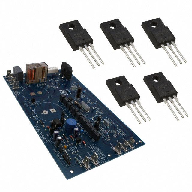
ICGOO电子元器件商城为您提供UCC28528EVM由Texas Instruments设计生产,在icgoo商城现货销售,并且可以通过原厂、代理商等渠道进行代购。 UCC28528EVM价格参考。Texas InstrumentsUCC28528EVM封装/规格:评估和演示板和套件, UCC28528 Power Factor Correction Power Management Evaluation Board。您可以下载UCC28528EVM参考资料、Datasheet数据手册功能说明书,资料中有UCC28528EVM 详细功能的应用电路图电压和使用方法及教程。
Texas Instruments(德州仪器)的UCC28528EVM是一款专门用于评估和演示UCC28528控制器性能的开发板。UCC28528是一款高效的电流模式PWM控制器,主要用于离线式反激式电源设计。以下是UCC28528EVM的主要应用场景:

 1. 反激式电源设计
UCC28528EVM特别适用于设计高效的反激式电源。反激式拓扑结构广泛应用于各种消费电子、工业设备和通信设备中的电源转换器。该评估板可以帮助工程师快速验证和优化基于UCC28528控制器的反激式电源设计,确保其在不同负载条件下的稳定性和效率。

 2. 高效能电源转换
UCC28528控制器内置了多种特性,如频率抖动、软启动、过流保护等,这些功能使得电源系统能够在宽输入电压范围内保持高效率和稳定性。UCC28528EVM允许用户通过调整参数来优化这些特性,从而实现更高效的电源转换,适用于需要长时间稳定运行的设备,如服务器电源、LED驱动器等。

 3. 低待机功耗应用
UCC28528EVM还适合用于需要低待机功耗的应用场景。UCC28528控制器具备自动跳周期功能,在轻载或无负载条件下可以显著降低待机功耗,这对于符合能源之星等节能标准的产品尤为重要,如家用电器、充电器和适配器等。

 4. 电源系统的调试与优化
对于电源设计工程师来说,UCC28528EVM提供了一个理想的平台来进行电源系统的调试和优化。通过该评估板,工程师可以轻松地调整控制器的各种参数,如开关频率、反馈环路增益等,以满足特定应用的需求。此外,UCC28528EVM还支持多种保护功能的测试,如过压保护、过流保护和短路保护等,确保电源系统的安全性和可靠性。

 5. 教育和培训
UCC28528EVM也可以作为教学工具,帮助学生和新手工程师理解反激式电源的工作原理和设计方法。通过实际操作和实验,学习者可以更好地掌握电源设计的基本概念和技术细节。

总之,UCC28528EVM为电源设计工程师提供了一个强大的工具,能够加速开发过程,优化电源性能,并确保最终产品的可靠性和高效性。
| 参数 | 数值 |
| 产品目录 | 编程器,开发系统半导体 |
| 描述 | EVALUATION MODULE FOR UCC28528电源管理IC开发工具 UCC28528 Eval Mod |
| 产品分类 | |
| 品牌 | Texas Instruments |
| 产品手册 | |
| 产品图片 |
|
| rohs | 否含铅 / 不符合限制有害物质指令(RoHS)规范要求 |
| 产品系列 | 电源管理IC开发工具,Texas Instruments UCC28528EVM- |
| 数据手册 | 点击此处下载产品Datasheethttp://www.ti.com/lit/pdf/sluu228 |
| 产品型号 | UCC28528EVM |
| 主要属性 | - |
| 主要用途 | 电源管理,功率因数校正 |
| 产品 | Evaluation Boards |
| 产品目录页面 | |
| 产品种类 | 电源管理IC开发工具 |
| 使用的IC/零件 | UCC28528 |
| 其它名称 | 296-21210 |
| 制造商产品页 | http://www.ti.com/general/docs/suppproductinfo.tsp?distId=10&orderablePartNumber=UCC28528EVM |
| 商标 | Texas Instruments |
| 尺寸 | 182.9 mm x 101.6 mm |
| 嵌入式 | - |
| 工具用于评估 | UCC28528 |
| 工厂包装数量 | 1 |
| 所含物品 | 板 |
| 标准包装 | 1 |
| 相关产品 | /product-detail/zh/UCC28528DW/296-18041-5-ND/770880/product-detail/zh/UCC28528DWG4/UCC28528DWG4-ND/1911769/product-detail/zh/UCC28528DWR/UCC28528DWR-ND/1911770/product-detail/zh/UCC28528DWRG4/UCC28528DWRG4-ND/1911771 |
| 类型 | Power Factor Correction |
| 辅助属性 | - |
| 输入电压 | 85 V to 265 V |
| 输出电压 | 380 V |


PDF Datasheet 数据手册内容提取
350-W Interleaved PFC Pre-Regulator User's Guide September 2005 System Power SLUU228
350-W Interleaved PFC Pre-Regulator User's Guide LiteratureNumber:SLUU228 September2005
Contents 1 Introduction................................................................................................................ 6 2 Description................................................................................................................. 6 3 ThermalRequirements................................................................................................. 6 4 ElectricalSpecifications............................................................................................... 6 5 Schematic.................................................................................................................. 7 6 TestSetup.................................................................................................................. 8 7 PowerUp/PowerDown................................................................................................ 9 8 PerformanceData....................................................................................................... 9 8.1 InputRippleCurrent............................................................................................... 11 8.2 StartupCharacteristics........................................................................................... 12 8.3 LineDropout....................................................................................................... 13 8.4 LineTransient...................................................................................................... 13 8.5 2-WAuxiliarySupply(V )...................................................................................... 14 bias 9 ReferenceDesignAssemblyDrawing.......................................................................... 15 10 BillofMaterials......................................................................................................... 16 ImportantNotices............................................................................................................... 20 SLUU228–September2005 TableofContents 3
List of Figures 1 AuxiliarySupplyandPFCControlCircuitry.............................................................................. 7 2 PFCPre-RegulatorPowerStage.......................................................................................... 8 3 TestSetup.................................................................................................................... 9 4 Efficiencyvs.OutputPower............................................................................................... 10 5 PFvs.OutputPower....................................................................................................... 10 6 CurrentTHDvs.OutputPower........................................................................................... 10 7 CurrentHarmonics......................................................................................................... 10 8 CurrentHarmonics......................................................................................................... 10 9 OutputRippleVoltageatFullLoad...................................................................................... 11 10 InputCurrentandInductorCurrents..................................................................................... 11 11 V =85VRMS,P =350W.......................................................................................... 12 IN OUT 12 V =265VRMS,P =350W......................................................................................... 12 IN OUT 13 Start-UpatV =120V,P =350W.................................................................................. 12 IN OUT 14 Start-UpatV =120V,P =0W..................................................................................... 12 IN OUT 15 V =120V,P =350W................................................................................................ 13 IN OUT 16 LineTransient,P =350W............................................................................................ 13 OUT 17 AuxiliaryGateDriveandCurrentSenseBehavioratNoLoad....................................................... 14 18 AuxiliaryOutputwith2-WLoad,GateDriveandCurrentSense,VOUT1=120V................................ 14 19 AuxiliaryOutputwith2-WLoad,GateDriveandCurrentSense,VOUT1=380V................................ 15 20 TopAssemblyLayer....................................................................................................... 15 21 BottomAssemblyLayer................................................................................................... 16 4 ListofFigures SLUU228–September2005
List of Tables 1 EVMSpecifications.......................................................................................................... 6 2 PartsList .................................................................................................................... 16 SLUU228–September2005 ListofTables 5
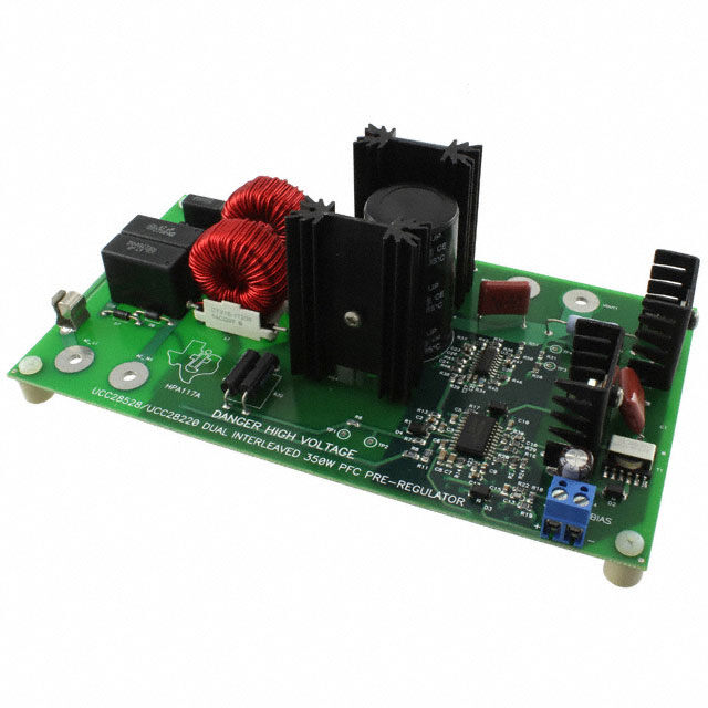
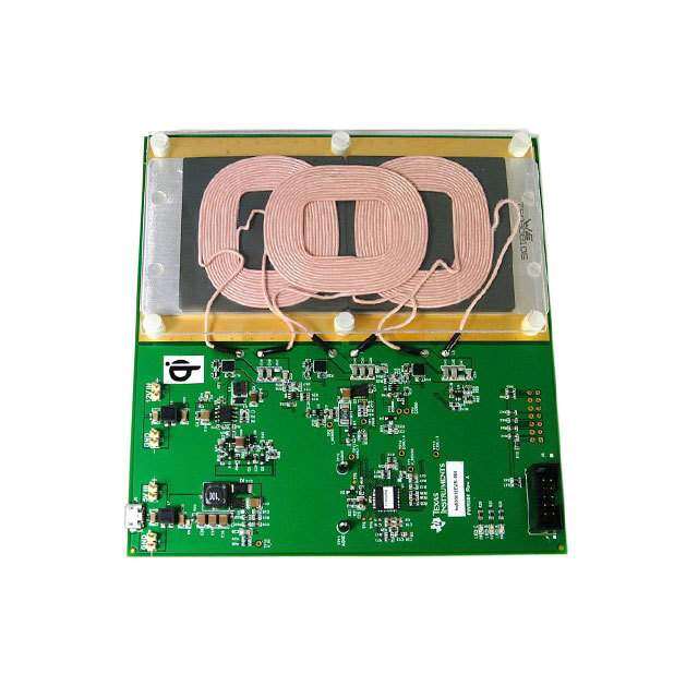
User's Guide SLUU228–September2005 350-W Interleaved PFC Pre-Regulator 1 Introduction Theevaluationmoduleisa350-W,twophaseinterleavedpowerfactorcorrectedpre-regulator.This evaluationmodulehasa380-V,350-W,dcoutputthatoperatesoffauniversalinputof(85Vto265V RMS)andprovidespowerfactorcorrection.TheunitmeetsEN61000-3-2classBinputcurrentharmonic specifications. 2 Description Thepre-regulatorusestheUCC28528PFC/PWMcombinationcontrollertoshapetheinputcurrentwave toprovidepowerfactorcorrection.Thisdevicealsocontrolsa2-Wauxiliarybiassupplythatcanbeused tocontrolexternalcircuitry.TheUCC28220interleavedPWMprovidesOVPprotectionandprovidesload sharingbetweenthetwointerleavedboostconverters. 3 Thermal Requirements 1. Theevaluationmoduleworksupto200Wwithoutexternalcooling. 2. Iftheunitistoberunover200W,itrequiresafanpointeddirectlyattheconverterheatsinks. 3. Itisimportanttokeeptheambienttemperaturearoundthecomponentsbelow40(cid:176) C. 4 Electrical Specifications Table1.EVMSpecifications Parameter TestConditions Min Typ Max Unit V Lineinputvoltage 85 265 V IN RMS P Outputpower 25 350 W OUT Efficiency 350W 90% V Outputvoltage 375 380 400 V OUT THD Totalharmonicdistortion 350W 10% 6 350-WInterleavedPFCPre-Regulator SLUU228–September2005
www.ti.com Schematic 5 Schematic + Figure1.AuxiliarySupplyandPFCControlCircuitry SLUU228–September2005 350-WInterleavedPFCPre-Regulator 7
www.ti.com TestSetup U4 1N/CUCC27324ND/C 8 2INA OUTA 7 3GND VDD 6 4INB OUTB 5 + + + Figure2.PFCPre-RegulatorPowerStage 6 Test Setup Therearehighvoltagespresentonthepre-regulatoranditshouldonlybehandledbyexperiencedpower supplyprofessionals.Toevaluatethisboardassafelyaspossiblethefollowingtestsetupshouldbe used.Anisolationtransformershouldbeconnectedbetweenthesourceandunit.Beforepoweris supplied,avoltmeterandaresistiveorelectronicloadshouldbeattachedtotheunit’soutput. 8 350-WInterleavedPFCPre-Regulator SLUU228–September2005
www.ti.com PowerUp/PowerDown FANNeededforGreater than200W FAN VM 50to350WLoad - IsolationTransformer Figure3.TestSetup 7 Power Up/Power Down Theunitwillstartupundernoloadconditions.However,forsafetyaloadshouldbeconnectedtothe outputofthedevicebeforeitispoweredup.Theunitshouldalsoneverbehandledwhenpowerisapplied toitortheoutputvoltageisabove50VDC. WARNING There are very high voltages on the board and components can and do reach temperatures above 50(cid:176) C so precautions must be taken in handling theboard. 8 Performance Data Theefficiencyoftheboostpre-regulatorisgreaterthan91%at20%load.Thisconverterinanormal systemwouldbefollowedbyastepdownconverter.Thenew+80initiativerequiresthecascadedpower supplybe80%efficientat20%load.Thiscanbeaccomplishedbyhavingthedownstreamconverter being90%efficientorgreater.Inhighpowerapplications,thiscanbeaccomplishedwithzerovoltage switching(ZVS).AnactiveclampforwardusingaUCC2894PWMoraphaseshiftedfullbridgeusingthe UCC2895PWMcouldbeusedtodesignastep-downconverterwithgreaterthan90%efficiencyforhigh powerapplications. SLUU228–September2005 350-WInterleavedPFCPre-Regulator 9
www.ti.com PerformanceData Efficiencyvs.OutputPower 97 96 95 % 94 a as Efficiency 9923 91 EfficiencyatVin=85V 90 EfficiencyatVin=265V 89 20 30 40 50 60 70 80 90 100 %ofOutputPower Figure4.Efficiencyvs.OutputPower PFvs.OutputPower 1 CurrentTHDvs.OutputPower 20 0.98 18 16 CurrentTHDatVin=85V 0.96 14 CurrentTHDatVin=265V PF 0.94 % 12 D 10 H T 0.92 8 PFatVin=85V 6 0.9 4 PFatVin=265V 2 0.88 20 30 40 50 60 70 80 90 100 0 15 25 35 45 55 65 75 85 95 %ofOutputPower %ofOutputPower Figure5.PFvs.OutputPower Figure6.CurrentTHDvs.OutputPower CurrentHarmonics Vin=85V,Pout=350W CurrentHarmonics Vin=265V,Pout=350W 4.63847 1.41845 3.86540 1.18204 A) 3.09234 Amplitude( 12..5341692207 plitude(A)00..7904952634 m 0.77313 A0.47283 0.00007 0.23643 0 2 4 6 8101214161820222426283032343638404244454850 0.00002 Harmonic 0 2 4 6 8101214161820222426283032343638404244464850 Harmonic Figure7.CurrentHarmonics Figure8.CurrentHarmonics 10 350-WInterleavedPFCPre-Regulator SLUU228–September2005
www.ti.com PerformanceData Figure9.OutputRippleVoltageatFullLoad 8.1 Input Ripple Current Figure10showsthattheinductorcurrentscanceleachotheroutleavingtheinputcurrentwaveform clean.CH1istherectifiedlinevoltage,Ch2istheinductorcurrentfromL1,CH3istheinductorcurrentof L2,Ch4istheconverterinputcurrent;CH1istherectifiedlinevoltage.Notetheconversionratioforthe currentwaveformis200mA/mV. CH1, Rectified Line Voltage CH4, Input Current CH3, L2 Current CH2, L1 Current Figure10.InputCurrentandInductorCurrents Figure11andFigure12showtherectifiedlinevoltage(CH1),inputcurrent(CH4),andL1andL2inductor currentsCH2andCH3respectively,atmaximumloadwithdifferentlineconditions.Fromthese waveforms,itcanbeobservedthattheinductorripplecurrentsarecancelingeachotheroutduetothe interleaving. SLUU228–September2005 350-WInterleavedPFCPre-Regulator 11
www.ti.com PerformanceData Rectified Line Input Current L2 Current L1 Current Figure11.V =85VRMS,P =350W IN OUT Figure12.V =265VRMS,P =350W IN OUT 8.2 Startup Characteristics PFCpre-regulatorshaveatendencytoovershootduringpowerup.Thisisduetothevoltageloop crossingoverat10Hz.However,theUCC28528usesaslewratecomparatorthatspeedsuptransient responseandreducesovershoot.Figure13andFigure14showthestartupbehavioroftheEVMat120-V RMSinputatmaximumandnoloadconditions.CH4istheoutputvoltageandCH3istheinputcurrent. Fromthesefigures,itcanbeobservedthatthereisverylittleovershootduringstartup. Output Voltage Input Current Figure13.Start-UpatV =120V,P =350W IN OUT Figure14.Start-UpatV =120V,P =0W IN OUT 12 350-WInterleavedPFCPre-Regulator SLUU228–September2005
www.ti.com PerformanceData 8.3 Line Dropout Theunitwastestedunderalinedropoutconditionandtheunitcamebackintoregulationwithin100ms. RefertoFigure15fordetails.CH1istherectifiedinputvoltageandCH2istheoutputvoltage. Output Voltage Rectified Line Voltage Figure15.V =120V,P =350W IN OUT 8.4 Line Transient Alinetransienttestwasconductedwithanacsourceonthereferencedesign.Thelinewasvariedfrom 120to240-VRMSandthetransientresponsewasevaluated.Fromtheoscilloscopeoutputshownin Figure16itcanbeobservedthattheoutputrecoveredwithin200ms. Output Voltage Rectified Line Voltage Figure16.LineTransient,P =350W OUT SLUU228–September2005 350-WInterleavedPFCPre-Regulator 13
www.ti.com PerformanceData 8.5 2-W Auxiliary Supply (V ) bias Theunithasa2-Wauxiliarybiassupplythatwasdesignedtooperatewithaboostvoltage(VOUT1)of 120Vto400V.ThisbiassupplyisbasedonaflybackconverterandalsoregulatesthePWM/PFCand gatedrivecircuitryoftheevaluationmodule.NotewhenV isnotloaded,thegatedriveoftheflybackis BIAS pulseskipping.OnceV hasbeenloaded,thegatedrivehasafixeddutycycle.RefertoFigure17, AUX Figure18,andFigure19fordetails. VOUT1 = 380 V P = 0 W vbias CH1 = V gateQ2 CH2 = V R5 CH3 = V bias Figure17.AuxiliaryGateDriveandCurrentSenseBehavioratNoLoad VOUT1 = 120 V P = 2 W Vbias CH1 = V gateQ2 CH2 = V R5 CH3 = V bias Figure18.AuxiliaryOutputwith2-WLoad,GateDriveandCurrentSense,VOUT1=120V 14 350-WInterleavedPFCPre-Regulator SLUU228–September2005
www.ti.com ReferenceDesignAssemblyDrawing VOUT1 = 380 V P = 0 W Vbias CH1 = V gateQ2 CH2 = V R5 CH3 = V bias Figure19.AuxiliaryOutputwith2-WLoad,GateDriveandCurrentSense,VOUT1=380V 9 Reference Design Assembly Drawing R2 R58 Figure20.TopAssemblyLayer SLUU228–September2005 350-WInterleavedPFCPre-Regulator 15
www.ti.com BillofMaterials Figure21.BottomAssemblyLayer 10 Bill of Materials Table2.PartsList RefDes Count Description MFR PartNumber AC_L1, 0 Connector,bindingpost,insulated,forstandardbananaplug, Johnson 111-0702-001 VOUT1 red,15A,0.425diaIn AC_N1, 0 Connector,bindingpost,insulated,forstandardbananaplug, Johnson 111-0703-001 RETURN1 black,15A,0.425diaIn C1,C33 2 Capacitor,polyester,.047m F,630V,10%,0.256x0.650 Panasonic ECQ-E6473KZ C10,C17, 3 Capacitor,ceramic,0.1m F,50V,X7R,10%,0805 Panasonic ECJ-2YB1H104K C18 C12 1 Capacitor,ceramic,0.68m F,16V,X7R,10%,0805 std std C13 1 Capacitor,ceramic,270pF,50V,X7R,10%,0805 std std C14 1 Capacitor,ceramic,0.47m F,16V,X7R,10%,0805 Panasonic ECJ-2YB1H104K C15 1 Capacitor,ceramic,0.027m F,50V,X7R,10%,0805 std std C16,C27 2 Capacitor,ceramic,180pF,50V,X7R,10%,0805 std std C19,C23, 4 Capacitor,ceramic,1.0m F,25V,X7R,10%,0805 std std C28,C35 C2 1 Capacitor,ceramic,3.9nF,50V,X7R,10%,0805 std std C20,C21 2 Capacitor,film,0.47m F,275V ,0.236· 0.591 Panasonic ECQ-U2A474MG AC C22 1 Capacitor,film,0.047m F,300V ,20– %,0.236· 0.591 Panasonic ECQ-U3A473MG AC C24,C26 2 Capacitor,ceramic,56pF,50V,NPO,5%,0603 std std C25 1 Capacitor,ceramic,0.47m F,16V,X7R,10%,0603 std std C29,C30 2 Capacitor,ceramic,47pF,50V,X7R,5%,0603 std std C3 1 Capacitor,ceramic,68pF,50V,X7R,10%,0805 std std C31,C32 2 CAP,tantalumchip,47m F,16V,0.281x0.126 Vishay 595D476X9016C2T 16 350-WInterleavedPFCPre-Regulator SLUU228–September2005
www.ti.com BillofMaterials Table2.PartsList (continued) RefDes Count Description MFR PartNumber C34 1 Capacitor,220m F,aluminumelectrolytic,450V ,-40/+85°C, Panasonic ECOS2WP221CX DC – 20%,0.984India. C4 1 Capacitor,330m F,aluminumelectrolytic,25V,Temp-55(cid:176) Cto Rubycon UPW1E331MPD6 105(cid:176) C°,– 20%,8x11.5mm C5 1 Capacitor,ceramic,10nF,50V,X7R,10%,0805 std std C6,C11 2 Capacitor,ceramic,100pF,50V,X7R,10%,0805 std std C7 1 Capacitor,ceramic,2.2m F,16V,X7R,10%,1206 std std C8 1 Capacitor,ceramic,1m F,25V,X7R,10%,1206 std std C9 1 Capacitor,ceramic,0.22m F,50V,X7R,10%,0805 std std D1 1 IC,adjustableprecisionshuntregulator,SOT-89 Texas TL431CPK Instruments D13,D14 2 Diode,schottkyrectifier,10A,600V,TO-263-2 CREE CSD10060G D15 1 Diode,zener,15V,350mW,SOT-23 Diodes,Inc. BZX84C15 D16 1 Diode,600V,6A,400Apeaksurge,P600 Diodes,Inc. 6A6-T D2 1 Diode,rectifier,1000mA,50V,SMA Diodes,Inc. RS1A D3,D4,D5 3 Diode,schottky,500mA,25V,SMA Vishay BYS10-25 Telefunken D6,D7 2 Diode,signal,600V,1A,DO-41 On 1N4005RL Semiconductor D8 1 6A,600Vbridgerectifier,GBJseries General PB66 Semiconductor D9,D10, 4 Diode,schottky,500mA,30V,SOD123 ON MBR0530 D11,D12 Semiconductor F1 1 Fuseholder,1/4fuses,0.42 Cooper/Bussman BK/1A1907-06 Fuse 1 4A,250V,3AGglassfastactingcartridgetype,1.25Inx.25In Littlefuse 312004 HS1,HS2 2 Heatsink,TO-220,verticalmount,15(cid:176) C/W,0.5x0.95 Aavid 593002B03400 HS3,HS4 2 Heatsink,TO-220,verticalmount,5(cid:176) C/W,0.5x1.38In Aavid 513201 J1 1 Terminalblock,2pin,15A,5.1mm,0.40x0.35 OST ED1609 **L1,L2 2 200m Hinductor,toroidverticalTHT,100kHz@2A,0.866x Cooper CTX16-17309 1.358In Q1 1 Transistor,switchingpowerNPN,1000V,5A,TO-220 OnSemi MJE18004 Q2,Q3,Q4 3 MOSFET,N-channel,500V,8A,750mW ,TO-220 International IRF840 Rectifier R1 1 Resistor,powermetalfilm,82kW ,3W,5– %,1,000X0.200 Panasonic ERG-3SJ823 R12,R17, 7 Resistor,chip,10kW ,1/10W,1%,0805 std std R21,R22, R39,R56, R57 R13 1 Resistor,chip,5.11kW ,1/10W,1%,0805 std std R14 1 Resistor,chip,30.1kW ,1/10W,1%,0805 std std R15 1 Resistor,chip,3.74kW ,1/10W,1%,0805 std std R16 1 Resistor,chip,2kW ,1/10W,1%,0805 std std R18 1 Resistor,chip,12.1kW ,1/10W,1%,0805 std std R19 1 Resistor,chip,20kW ,1/10W,1%,0805 std std R2 1 Resistor,chip,110kW ,1/10W,1%,0805 std std R20 1 Resistor,chip,316kW ,1/10W,1%,0805 std std R23 1 Resistor,chip,34kW ,1/10W,1%,0805 std std R24 1 Resistor,chip,22.1kW ,1/10W,1%,0805 std std R25,R28 2 Resistor,chip,562kW ,1/8W,1%,0805 std std R26 1 Resistor,chip,15kW ,1/10W,01%,0805 std std SLUU228–September2005 350-WInterleavedPFCPre-Regulator 17
www.ti.com BillofMaterials Table2.PartsList (continued) RefDes Count Description MFR PartNumber R27 1 Resistor,chip,100W ,1/8W,0.1%,1206 std std R29,R40, 3 Resistor,chip,1kW ,1/10W,1%,0805 std std R41 R3 1 Resistor,chip,28.0kW ,1/10W,1%,0805 std std R30 1 Resistor,chip,9.09kW ,1/10W,1%,0805 Panasonic ERJ-6ENF9091V R32,R33 2 Resistorcurrentsense0.20W 3W,0.600· 0.250In Ohmite 13FR200 R34 1 Resistor,chip,59kW ,1/10W,5%,0805 std std R35 1 Resistor,chip,13.3kW ,1/10W,1%,0805 std std R36 1 Resistor,chip,38.3kW ,1/10W,1%,0805 std std R37 1 Resistor,chip,20.0W ,1/4W,1%,1206 std std R38 1 Resistor,chip,6.81kW ,1/10W,1%,0805 std std R4 1 Resistor,powermetalfilm,500V10kW ,3W,5– %,1,000X Panasonic ERG-3SJ103 0.200 R42 1 Resistor,chip,2.94kW ,1/8W,1%,805 std std R43,R44 2 Resistor,chip,6.04kW ,1/10W,1%,1206 std std R45 1 Resistor,chip,20.5kW ,1/10W,1%,0805 std std R46 1 Resistor,chip,80.6kW ,1/10W,1%,0805 std std R47,R50, 3 Resistor,chip,324kW ,1/10W,1%,0805 std std R51 R48,R49 2 Resistor,chip,100W ,1/10W,1%,0805 std std R5 1 Resistor,cabonfilm,4.3W 1/4W,5%,Axial,RN55 YAGEO CFR-25JB-4R3 R52,R54 2 Resistor,chip,0W ,1/10W,5%,0805 std std R53,R55 2 Resistor,chip,5.23W ,1/10W,1%,0805 std std R6,R31 2 Resistor,chip,47W ,1/10W,1%,0805 std std R7,R10 2 Resistor,chip,2.32kW ,1/10W,1%,0805 std std R8,R11 2 Resistor,chip,390kW ,1/8W,1%,1206 std std R9 1 Resistor,chip,1.5kW ,1/10W,1%,0805 std std **T1 1 Inductor,dual-coupled,9:1,0.559x0.508In Cooper CTX16-17169 **T2,T3 2 Transformer,currentsense,10A,500kHz,1:50,0.330x0.360 Pulse PA1005.050 TP1,TP2, 4 Jack,testpoint,clrcle Farnell 240-3xx TP3,TP4 **U1 1 IC,BiCMOSPFC\PWMController,SOP20(DW) TI UCC28528DW **U2 1 IC,Precisionop-amp,SO8 TI OP07DD **U3 1 IC,DualinterleavedPWMcontrollerwithprogrammablemax TI UCC28220D dutycycle,SO16 **U4 1 IC,HighspeedlowsidepowerMOSFETdriver,SO8 TI UCC27324D X1@HS1, 4 Thermalpadsilicon,TO-220size BERQUIST 3223-07FR-51 HS2,HS3, HS4 X1@HS1, 4 Nut#4-40(steel) HS2,HS3, HS4 X1@HS1, 4 Splitlockwasher#4(steel) HS2,HS3, HS4 X1@HS1, 4 Flatwasher#4(steel) HS2,HS3, HS4 X1@HS1, 4 Nylonshoulderwasher#4 Keystone 3049 HS2,HS3, Electronics HS4 18 350-WInterleavedPFCPre-Regulator SLUU228–September2005
www.ti.com BillofMaterials Table2.PartsList (continued) RefDes Count Description MFR PartNumber X1@HS1, 4 Panheadscrew#4-40X3/8(steel) HS2,HS3, HS4 Standoff 4 Panheadscrew#6X321/4nylon,usedwithstandoffs Standoff 4 Standoff6/32thrd3/8· 3/8In Daburn 10-42 Electronics -- 1 PCB,0Inx0Inx0In Any HPA117A SLUU228–September2005 350-WInterleavedPFCPre-Regulator 19
FCCWarnings Thisequipmentisintendedforuseinalaboratorytestenvironmentonly.Itgenerates,uses,and canradiateradiofrequencyenergyandhasnotbeentestedforcompliancewiththelimitsof computingdevicespursuanttosubpartJofpart15ofFCCrules,whicharedesignedtoprovide reasonableprotectionagainstradiofrequencyinterference.Operationofthisequipmentinother environmentsmaycauseinterferencewithradiocommunications,inwhichcasetheuserathis ownexpensewillberequiredtotakewhatevermeasuresmayberequiredtocorrectthis interference. EVMWARNINGSANDRESTRICTIONS ItisimportanttooperatethisEVMwithintheinputvoltagerangeof85Vto125VRMSandthe outputvoltagerangeof374Vto425V. Exceedingthespecifiedinputrangemaycauseunexpectedoperationand/orirreversibledamage totheEVM.Iftherearequestionsconcerningtheinputrange,pleasecontactaTIfield representativepriortoconnectingtheinputpower. Applyingloadsoutsideofthespecifiedoutputrangemayresultinunintendedoperationand/or possiblepermanentdamagetotheEVM.PleaseconsulttheEVMUser'sGuidepriorto connectinganyloadtotheEVMoutput.Ifthereisuncertaintyastotheloadspecification,please contactaTIfieldrepresentative. Duringnormaloperation,somecircuitcomponentsmayhavecasetemperaturesgreaterthan 50(cid:176) C.TheEVMisdesignedtooperateproperlywithcertaincomponentsabove50(cid:176) Caslongas theinputandoutputrangesaremaintained.Thesecomponentsincludebutarenotlimitedto linearregulators,switchingtransistors,passtransistors,andcurrentsenseresistors.Thesetypes ofdevicescanbeidentifiedusingtheEVMschematiclocatedintheEVMUser'sGuide.When placingmeasurementprobesnearthesedevicesduringoperation,pleasebeawarethatthese devicesmaybeverywarmtothetouch. MailingAddress:TexasInstruments,PostOfficeBox655303,Dallas,Texas75265 Copyright©2005,TexasInstrumentsIncorporated
IMPORTANT NOTICE Texas Instruments Incorporated and its subsidiaries (TI) reserve the right to make corrections, modifications, enhancements, improvements, and other changes to its products and services at any time and to discontinue any product or service without notice. Customers should obtain the latest relevant information before placing orders and should verify that such information is current and complete. All products are sold subject to TI’s terms and conditions of sale supplied at the time of order acknowledgment. TI warrants performance of its hardware products to the specifications applicable at the time of sale in accordance with TI’s standard warranty. Testing and other quality control techniques are used to the extent TI deems necessary to support this warranty. Except where mandated by government requirements, testing of all parameters of each product is not necessarily performed. TI assumes no liability for applications assistance or customer product design. Customers are responsible for their products and applications using TI components. To minimize the risks associated with customer products and applications, customers should provide adequate design and operating safeguards. TI does not warrant or represent that any license, either express or implied, is granted under any TI patent right, copyright, mask work right, or other TI intellectual property right relating to any combination, machine, or process in which TI products or services are used. Information published by TI regarding third-party products or services does not constitute a license from TI to use such products or services or a warranty or endorsement thereof. Use of such information may require a license from a third party under the patents or other intellectual property of the third party, or a license from TI under the patents or other intellectual property of TI. Reproduction of information in TI data books or data sheets is permissible only if reproduction is without alteration and is accompanied by all associated warranties, conditions, limitations, and notices. Reproduction of this information with alteration is an unfair and deceptive business practice. TI is not responsible or liable for such altered documentation. Resale of TI products or services with statements different from or beyond the parameters stated by TI for that product or service voids all express and any implied warranties for the associated TI product or service and is an unfair and deceptive business practice. TI is not responsible or liable for any such statements. Following are URLs where you can obtain information on other Texas Instruments products and application solutions: Products Applications Amplifiers amplifier.ti.com Audio www.ti.com/audio Data Converters dataconverter.ti.com Automotive www.ti.com/automotive DSP dsp.ti.com Broadband www.ti.com/broadband Interface interface.ti.com Digital Control www.ti.com/digitalcontrol Logic logic.ti.com Military www.ti.com/military Power Mgmt power.ti.com Optical Networking www.ti.com/opticalnetwork Microcontrollers microcontroller.ti.com Security www.ti.com/security Telephony www.ti.com/telephony Video & Imaging www.ti.com/video Wireless www.ti.com/wireless Mailing Address: Texas Instruments Post Office Box 655303 Dallas, Texas 75265 Copyright 2005, Texas Instruments Incorporated