ICGOO在线商城 > 集成电路(IC) > PMIC - PFC(功率因数修正) > UCC28019P
 Datasheet下载
- 型号: UCC28019P
- 制造商: Texas Instruments
- 库位|库存: xxxx|xxxx
- 要求:
| 数量阶梯 | 香港交货 | 国内含税 |
| +xxxx | $xxxx | ¥xxxx |
查看当月历史价格
查看今年历史价格
UCC28019P产品简介:
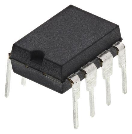
ICGOO电子元器件商城为您提供UCC28019P由Texas Instruments设计生产,在icgoo商城现货销售,并且可以通过原厂、代理商等渠道进行代购。 UCC28019P价格参考¥5.85-¥5.85。Texas InstrumentsUCC28019P封装/规格:PMIC - PFC(功率因数修正), PFC IC Continuous Conduction (CCM) 65kHz 8-PDIP。您可以下载UCC28019P参考资料、Datasheet数据手册功能说明书,资料中有UCC28019P 详细功能的应用电路图电压和使用方法及教程。
UCC28019P 是 Texas Instruments(德州仪器)推出的一款用于功率因数校正(PFC)的电源管理集成电路(PMIC),主要应用于中高功率开关电源系统中,以提高电源效率和减少电网谐波污染。

该芯片常用于以下场景:

1. 工业电源系统:如变频器、伺服驱动器、工业电源模块等,用于提升输入端的功率因数,降低对电网的干扰。
2. 通信电源设备:在通信基站、服务器电源、UPS不间断电源中,作为前端PFC控制器,优化电能利用率。
3. 家电与白色家电:如大功率空调、电磁炉、高端洗衣机等,满足日益严格的能效法规要求。
4. LED照明电源:用于高功率LED路灯或商业照明系统中,确保电源符合高功率因数标准。
5. 电动汽车充电设备:作为车载充电机或充电桩电源模块中的PFC控制单元,提升充电效率和电网兼容性。

UCC28019P 支持多种工作模式(如连续导通模式、临界导通模式),具备过压、欠压、过流等多种保护功能,适用于升压型PFC拓扑结构,具有良好的稳定性和适应性,适合广泛应用于需要高效能电源转换的场合。
| 参数 | 数值 |
| 产品目录 | 集成电路 (IC)半导体 |
| 描述 | IC CCM PFC CONTROLLER 8-DIP功率因数校正 - PFC 8Pin Cont Cond Mode PFC Cntlr |
| DevelopmentKit | UCC28019EVM |
| 产品分类 | |
| 品牌 | Texas Instruments |
| 产品手册 | |
| 产品图片 |
|
| rohs | 符合RoHS无铅 / 符合限制有害物质指令(RoHS)规范要求 |
| 产品系列 | 电源管理 IC,功率因数校正 - PFC,Texas Instruments UCC28019P- |
| 数据手册 | |
| 产品型号 | UCC28019P |
| 产品目录页面 | |
| 产品种类 | 功率因数校正 - PFC |
| 供应商器件封装 | 8-PDIP |
| 其它名称 | 296-21937-5 |
| 包装 | 管件 |
| 单位重量 | 523.200 mg |
| 参考设计库 | http://www.digikey.com/rdl/4294959902/4294959897/378 |
| 商标 | Texas Instruments |
| 安装类型 | 通孔 |
| 安装风格 | Through Hole |
| 封装 | Tube |
| 封装/外壳 | 8-DIP(0.300",7.62mm) |
| 封装/箱体 | PDIP-8 |
| 工作温度 | -40°C ~ 125°C |
| 工厂包装数量 | 50 |
| 开关频率 | 71 kHz |
| 最大工作温度 | + 125 C |
| 最小工作温度 | - 40 C |
| 标准包装 | 50 |
| 模式 | 连续导电(CCM) |
| 电压-电源 | 10 V ~ 21 V |
| 电流-启动 | 100µA |
| 系列 | UCC28019 |
| 配用 | /product-detail/zh/UCC28019EVM/296-23116-ND/1805636 |
| 频率-开关 | 65kHz |


- 商务部:美国ITC正式对集成电路等产品启动337调查
- 曝三星4nm工艺存在良率问题 高通将骁龙8 Gen1或转产台积电
- 太阳诱电将投资9.5亿元在常州建新厂生产MLCC 预计2023年完工
- 英特尔发布欧洲新工厂建设计划 深化IDM 2.0 战略
- 台积电先进制程称霸业界 有大客户加持明年业绩稳了
- 达到5530亿美元!SIA预计今年全球半导体销售额将创下新高
- 英特尔拟将自动驾驶子公司Mobileye上市 估值或超500亿美元
- 三星加码芯片和SET,合并消费电子和移动部门,撤换高东真等 CEO
- 三星电子宣布重大人事变动 还合并消费电子和移动部门
- 海关总署:前11个月进口集成电路产品价值2.52万亿元 增长14.8%


PDF Datasheet 数据手册内容提取
UCC28019 www.ti.com SLUS755B–APRIL2007–REVISEDDECEMBER2007 8-Pin Continuous Conduction Mode (CCM) PFC Controller FEATURES DESCRIPTION 1 • 8-pinSolutionWithoutSensingLineVoltage The UCC28019 8-pin active Power Factor Correction ReducesExternalComponents (PFC) controller uses the boost topology operating in • Wide-RangeUniversalACInputVoltage Continuous Conduction Mode (CCM). The controller is suitable for systems in the 100 W to >2 kW range • Fixed65-kHzOperatingFrequency over a wide-range universal ac line input. Startup • MaximumDutyCycleof97% current during under-voltage lockout is less than 200 • OutputOver/Under-VoltageProtection m A. The user can control low power standby mode by • InputBrown-OutProtection pullingtheVSENSEpinbelow0.77V. • Cycle-by-CyclePeakCurrentLimiting Low-distortion wave-shaping of the input current using average current mode control is achieved • OpenLoopDetection without input line sensing, reducing the Bill of • Low-PowerUserControlledStandbyMode Materials component count. Simple external networks allow for flexible compensation of the current and APPLICATIONS voltage control loops. The switching frequency is • CCMBoostPowerFactorCorrectionPower internally fixed and trimmed to better than 5% Convertersinthe100Wto>2kWRange accuracyat25(cid:176) C.Fast1.5-Agatepeak current drives • ServerandDesktopPowerSupplies theexternalswitch. • TelecomRectifiers Numerous system-level protection features include • IndustrialElectronics peak current limit, soft over-current detection, open-loop detection, input brown-out detection, • HomeElectronics output over-voltage protection/under-voltage detection, a no-power discharge path on VCOMP, CONTENTS and overload protection on ICOMP. Soft-Start limits • ElectricalCharacteristics3 boost current during start-up. A trimmed internal • DeviceInformation10 reference provides accurate protection thresholds • ApplicationInformation12 and regulation set-point. An internal clamp limits the gatedrivevoltageto12.5V. • DesignExample23 • AdditionalReferences43 TYPICAL APPLICATION DIAGRAM EMIFilter VOUT LINE – Bridge + INPUT Rectifier 1 GND GATE 8 2 ICOMP VCC 7 ASuuxpilpalryy 3 ISENSE VSENSE 6 4 VINS VCOMP 5 Rload UCC28019 1 Pleasebeawarethatanimportantnoticeconcerningavailability,standardwarranty,anduseincriticalapplicationsof TexasInstrumentssemiconductorproductsanddisclaimerstheretoappearsattheendofthisdatasheet. PRODUCTIONDATAinformationiscurrentasofpublicationdate. Copyright©2007,TexasInstrumentsIncorporated Products conform to specifications per the terms of the Texas Instruments standard warranty. Production processing does not necessarilyincludetestingofallparameters.
UCC28019 www.ti.com SLUS755B–APRIL2007–REVISEDDECEMBER2007 ORDERINGINFORMATION PARTNUMBER PACKAGE(1) OPERATINGTEMPERATURE RANGE,T A UCC28019D SOIC8-Pin(D)ead(Pb)-Free/Green PlasticDIP8Pin(P)Lead –40(cid:176) Cto125(cid:176) C UCC28019P (Pb)-Free/Green (1) SOIC(D)packageisavailabletapedandreeledbyadding"R"suffixthetheabovepartnumber,reeledquantitiesare2500devicesper reel. ABSOLUTE MAXIMUM RATINGS(1) overoperatingfree-airtemperaturerange(unlessotherwisenoted) VALUE UNIT VCC –0.3to22 GATE –0.3to16 Inputvoltagerange V VINS,VSENSE,VCOMP,ICOMP –0.3to7 ISENSE –24to7 Inputcurrentrange VSENSE,ISENSE –1to1 mA Operating –55to150 Junctiontemperature,T J Storage –65to150 (cid:176) C Leadtemperature,T Soldering,10s 300(cid:176) SOL (1) Stressesbeyondthoselistedunder“AbsoluteMaximumRatings”maycausepermanentdamagetothedevice.Thesearestressratings onlyandfunctionaloperationofthedeviceattheseoranyotherconditionbeyondthoseincludedunder“RecommendedOperating Conditions”isnotimplied.Exposuretoabsolute-maximum-ratedconditionsforextendedperiodsoftimemayaffectdevicereliability. DISSIPATION RATINGS(1) PACKAGE THERMALIMPEDANCE T =25(cid:176) CPOWERRATING(W) T =85(cid:176) CPOWERRATING(W) A A JUNCTIONTOAMBIENT((cid:176) C/W) SOIC-8(D) 160 0.65 0.25 PDIP-8(P) 110 1 0.36 (1) TestedperJEDECEIA/JESD51-1.Thermalresistanceisastrongfunctionofboardconstructionandlayout.Airflowreducesthermal resistance.Thisnumberisonlyageneralguide.SeeTIdocumentSPRA953ThermalMetrics. RECOMMENDED OPERATING CONDITIONS overoperatingfree-airtemperaturerange(unlessotherwisenoted) PARAMETER MIN MAX UNIT VCCinputvoltagefromalow-impedancesource VCC +1V 21 V OFF(max) T Operatingjunctiontemperature –40 125 (cid:176) C J ELECTROSTATIC DISCHARGE (ESD) PROTECTION overoperatingfree-airtemperaturerange(unlessotherwisenoted) PARAMETER RATING UNIT HumanBodyModel(HBM) 2 kV ChargedDeviceModel(CDM) 500 V 2 SubmitDocumentationFeedback Copyright©2007,TexasInstrumentsIncorporated ProductFolderLink(s): UCC28019
UCC28019 www.ti.com SLUS755B–APRIL2007–REVISEDDECEMBER2007 ELECTRICAL CHARACTERISTICS Unlessotherwisenoted,VCC=15V ,0.1m FfromVCCtoGND,-40(cid:176) C≤T =T ≤125(cid:176) C.Allvoltagesarewithrespectto DC J A GND.Currentsarepositiveintoandnegativeoutofthespecifiedterminal. PARAMETER TESTCONDITIONS MIN TYP MAX UNIT VCCBiasSupply I Pre-startcurrent VCC=VCC –0.1V 25 100 200 m A VCC(start) ON I Standbycurrent VSENSE=0.5V 1.0 2.1 2.9 VCC(stby) mA I Operatingcurrent VSENSE=4.5V,C =4.7nF 4 7 10 VCC(on_load) GATE UnderVoltageLockout(UVLO) VCC Turnonthreshold 10.0 10.5 11.0 ON VCC Turnoffthreshold 9 9.5 10 V OFF UVLO Hysteresis 0.8 1.0 1.2 Oscillator T =25(cid:176) C 61.7 65.0 68.3 A f Switchingfrequency, kHz SW –40(cid:176) C≤T ≤125(cid:176) C 59 65 71 A PWM VCOMP=0V,VSENSE=5V, D Minimumdutycycle 0% MIN ICOMP=6.4V D Maximumdutycycle VSENSE=4.95V 94% 97% 99.3% MAX t Minimumofftime VSENSE=3V,ICOMP=1V 100 250 600 ns OFF(min) SystemProtection ISENSEthreshold,softovercurrent V -0.66 -0.73 -0.79 SOC (SOC), ISENSEthreshold,peakcurrentLimit V -1.00 -1.08 -1.15 V PCL (PCL), VSENSEthreshold,openloop ICOMP=1V,ISENSE=0V, V 0.77 0.82 0.86 OLP protection(OLP), VCOMP=1V Openloopprotection(OLP)internal VSENSE=0.5V 100 250 nA pull-downcurrent VSENSEthreshold,output V 4.63 4.75 4.87 UVD under-voltagedetection(UVD), VSENSEthreshold,output V ISENSE=-0.2V 5.12 5.25 5.38 OVP over-voltageprotection(OVP), V Inputbrown-outdetection(IBOP) VINS 0.76 0.82 0.88 BROWNOUT_th high-to-lowthreshold Inputbrown-outDetection(IBOP) VINS 1.4 1.5 1.6 ENABLE_th low-to-highthreshold I VINSbiascurrent VINS=0V 0 ±0.1 m A VINS_0V ICOMPthreshold,externaloverload 0.6 V protection Copyright©2007,TexasInstrumentsIncorporated SubmitDocumentationFeedback 3 ProductFolderLink(s): UCC28019
UCC28019 www.ti.com SLUS755B–APRIL2007–REVISEDDECEMBER2007 ELECTRICAL CHARACTERISTICS (continued) Unlessotherwisenoted,VCC=15V ,0.1m FfromVCCtoGND,-40(cid:176) C≤T =T ≤125(cid:176) C.Allvoltagesarewithrespectto DC J A GND.Currentsarepositiveintoandnegativeoutofthespecifiedterminal. PARAMETER TESTCONDITIONS MIN TYP MAX UNIT CurrentLoop gmi Transconductancegain T =25(cid:176) C 0.75 0.95 1.15 mS A Outputlinearrange 50 m A ICOMPvoltageduringOLP VSENSE=0.5V 3.7 4.0 4.3 V VoltageLoop V Referencevoltage -40(cid:176) C≤T ≤125(cid:176) C 4.90 5.00 5.10 V REF A gmv Transconductancegain 31.5 42 52.5 m S Maximumsinkcurrentundernormal VSENSE=6V,VCOMP=4V 21 30 38 operation Sourcecurrentundersoftstart VSENSE=4V,VCOMP=0V –21 -30 -38 m A MaximumsourcecurrentunderEDR VSENSE=4V,VCOMP=0V –100 –170 –250 operation VSENSE=4V,VCOMP=4V –60 –100 –140 Enhanceddynamicresponse,V SENSE 4.63 4.75 4.87 V lowthreshold,falling V inputbiascurrent 1V≤VSENSE≤5V 100 250 nA SENSE V voltageduringOLP VSENSE=0.5V,I =0.5mA 0 0.2 0.4 V COMP VCOMP GATEDriver GATEcurrent,peak,sinking(1) C =4.7nF 2.0 GATE A GATEcurrent,peak,sourcing(1) C =4.7nF –1.5 GATE GATErisetime C =4.7nF,GATE=2Vto8V 40 60 GATE ns GATEfalltime C =4.7nF,GATE=8Vto2V 25 40 GATE GATElowvoltage,noload GATE=0A 0 0.05 GATElowvoltage,sinking GATE=20mA 0.3 0.8 GATElowvoltage,sourcing GATE=-20mA –0.3 –0.8 GATElowvoltage,sinking VCC=5V,GATE=5mA 0.2 0.75 1.2 GATElowvoltage,sinking VCC=5V,GATE=20mA 0.2 0.9 1.5 V GATEhighvoltage VCC=20V,C =4.7nF 11 12.5 14 GATE GATEhighvoltage VCC=11V,C =4.7nF 9.5 10.5 11.0 GATE VCC=VCC +0.2V, GATEhighvoltage OFF 8.0 9.0 10.2 C =4.7nF GATE (1) Nottested.Characterizedbydesign. 4 SubmitDocumentationFeedback Copyright©2007,TexasInstrumentsIncorporated ProductFolderLink(s): UCC28019
UCC28019 www.ti.com SLUS755B–APRIL2007–REVISEDDECEMBER2007 TYPICAL CHARACTERISTICS Unless otherwise noted, VCC = 15 V , 0.1 m F from VCC to GND, T = T = 25(cid:176) C. All voltages are with respect DC J A toGND.Currentsarepositiveintoandnegativeoutofthespecifiedterminal. UVLOTHRESHOLDS SUPPLYCURRENT vs vs TEMPERATURE BIASSUPPLYVOLTAGE 12.0 4.0 VSENSE=VINS=3V 3.5 NoGateLoad V - hold 11.0 VCCTurnON(VCCON) mA 3.0 s - hre ent 2.5 OT urr L C 2.0 I TurnOFF I TurnON V 10.0 y VCC VCC U pl - p FF Su 1.5 O C - C CC C/VON 9.0 VCCTurnOFF(VCCOFF) IV 1.0 C V 0.5 0 8.0 0 5 10 15 20 -60 -35 -10 15 40 65 90 115 140 VCC-BiasSupplyVoltage-V T -Temperature-°C J Figure1. Figure2. SUPPLYCURRENT SUPPLYCURRENT vs vs TEMPERATURE TEMPERATURE 10 0.5 9 VCC=VCC -0.1V ON 8 0.4 A A m m 7 Operating,GATELoad=4.7nF - - I nt nt 6 VCC(on_load) re 0.3 re ur ur C C 5 y y pl uppl 4 Sup 0.2 S - I-VCC 3 SIVtCaCn(sdtbbyy) CC(start) (PIVrCeC-S(sttaartr)t) V 2 I 0.1 1 0 0 -60 -35 -10 15 40 65 90 115 140 -60 -35 -10 15 40 65 90 115 140 T -Temperature-°C T -Temperature-°C J J Figure3. Figure4. Copyright©2007,TexasInstrumentsIncorporated SubmitDocumentationFeedback 5 ProductFolderLink(s): UCC28019
UCC28019 www.ti.com SLUS755B–APRIL2007–REVISEDDECEMBER2007 TYPICAL CHARACTERISTICS (continued) OSCILLATORFREQUENCY OSCILLATORFREQUENCY vs vs TEMPERATURE BIASSUPPLYVOLTAGE 75 75 73 73 z 71 z 71 H H k k - 69 - 69 y y c c n n ue 67 SwitchingFrequency ue 67 SwitchingFrequency q q e e Fr 65 Fr 65 g g n n hi 63 hi 63 c c wit wit S 61 S 61 - - W W fS 59 fS 59 57 57 55 55 -60 -35 -10 15 40 65 90 115 140 10 12 14 16 18 20 T -Temperature-°C VCC-BiasSupplyVoltage-V J Figure5. Figure6. CURRENTAVERAGING VOLTAGEERRORAMPLIFIER AMPLIFIERTRANSCONDUCTANCE TRANSCONDUCTANCE vs vs TEMPERATURE TEMPERATURE 2.0 50 1.8 48 1.6 46 1.4 44 Gain V mA/ 1.2 Gain A/V 42 µ - - n 1.0 n ai ai 40 G G mi- 0.8 v- 38 m g g 0.6 36 0.4 34 0.2 32 0 30 -60 -35 -10 15 40 65 90 115 140 -60 -35 -10 15 40 65 90 115 140 T -Temperature-°C J T -Temperature-°C J Figure7. Figure8. 6 SubmitDocumentationFeedback Copyright©2007,TexasInstrumentsIncorporated ProductFolderLink(s): UCC28019
UCC28019 www.ti.com SLUS755B–APRIL2007–REVISEDDECEMBER2007 TYPICAL CHARACTERISTICS (continued) VSENSETHRESHOLD VSENSETHRESHOLD vs vs TEMPERATURE TEMPERATURE 2.0 5.50 1.8 V 1.6 V d- 5.25 - ol d 1.4 h ol s Over-VoltageProtection(V ) h e OVP hres 1.2 EThr SET 1.0 OpenLoopProtection(VOLP) ENS 5.00 N S E 0.8 V VS -VD –P 0.6 VU VOL /VP 4.75 0.4 VO Under-VoltageProtection(V ) UVD 0.2 0 4.50 -60 -35 -10 15 40 65 90 115 140 -60 -35 -10 15 40 65 90 115 140 TJ-Temperature-°C TJ-Temperature-°C Figure9. Figure10. VINSTHRESHOLD ISENSETHRESHOLD vs vs TEMPERATURE TEMPERATURE 2.0 0 V - old 1.8 -0.1 h s Thre 1.6 V -0.2 VINS 1.4 VINSEnable(VINSENABLE_TH) hold- -0.3 – 1.2 s -0.4 e UT_TH 1.0 EThr -0.5 VINSBROUWNO 00..86 InputBrown-OutProtection(VINSBROWNOUT_TH) V-ISENSSOC --00..67 SoftOver-CurrentProtection(SOC) / -0.8 H 0.4 T E_ ABL 0.2 -0.9 N E S N 0 -1.0 VI -60 -35 -10 15 40 65 90 115 140 -60 -35 -10 15 40 65 90 115 140 TJ-Temperature-°C TJ-Temperature-°C Figure11. Figure12. Copyright©2007,TexasInstrumentsIncorporated SubmitDocumentationFeedback 7 ProductFolderLink(s): UCC28019
UCC28019 www.ti.com SLUS755B–APRIL2007–REVISEDDECEMBER2007 TYPICAL CHARACTERISTICS (continued) MINIMUMOFFTIME GATEDRIVESWITCHING vs vs TEMPERATURE TEMPERATURE 600 50 VSENSE=3V C =4.7nF 550 45 GATE ICOMP=1V V =2V-8V GATE 500 40 450 35 s 400 s 30 n n - - me 350 me 25 FallTime Ti Ti t- 300 t t- 20 OFF(min) 250 15 RiseTime 200 10 105 5 100 0 -60 -35 -10 15 40 65 90 115 140 -60 -35 -10 15 40 65 90 115 140 T -Temperature-°C T -Temperature-°C J J Figure13. Figure14. GATEDRIVESWITCHING GATELOWVOLTAGE vs WITHDEVICEOFF BIASSUPPLYVOLTAGE vs 50 TEMPERATURE 2.0 C =4.7nF 45 VGAGTAETE=2V-8V 1.8 IVCC=2=05mVA VCC 40 1.6 V 35 - e 1.4 g ns 30 olta 1.2 V - RiseTime V GATE me 25 w o 1.0 Ti L t- 20 FallTime Gate 0.8 15 – TE 0.6 A G 10 V 0.4 5 0.2 0 0 10 12 14 16 18 20 VCC-BiasSupplyVoltage-V -60 -35 -10 15 40 65 90 115 140 T -Temperature-°C J Figure15. Figure16. 8 SubmitDocumentationFeedback Copyright©2007,TexasInstrumentsIncorporated ProductFolderLink(s): UCC28019
UCC28019 www.ti.com SLUS755B–APRIL2007–REVISEDDECEMBER2007 TYPICAL CHARACTERISTICS (continued) REFERENCEVOLTAGE vs TEMPERATURE 5.50 VCC=15V V 5.25 - e g a olt ReferenceVoltage V e c 5.00 n e r e ef R - F E R V 4.75 4.50 -60 -35 -10 15 40 65 90 115 140 T -Temperature-°C J Figure17. Copyright©2007,TexasInstrumentsIncorporated SubmitDocumentationFeedback 9 ProductFolderLink(s): UCC28019
UCC28019 www.ti.com SLUS755B–APRIL2007–REVISEDDECEMBER2007 DEVICE INFORMATION Connection Diagram UCC28019TopView(SOIC-8,PDIP-8) 1 GND GATE 8 2 ICOMP VCC 7 3 ISENSE VSENSE 6 4 VINS VCOMP 5 Pin Descriptions TerminalFunctions TERMINAL I/O FUNCTION NAME # Gatedrive:Integratedpush-pullgatedriverforoneormoreexternalpowerMOSFETs.2.0-Asinkand1.5-A GATE 8 O sourcecapability.Outputvoltageisclampedat12.5V. GND 1 Ground:Devicegroundreference. Currentloopcompensation:Transconductancecurrentamplifieroutput.AcapacitorconnectedtoGND ICOMP 2 O providescompensationandaveragingofthecurrentsensesignalinthecurrentcontrolloop.Thecontrolleris disabledifthevoltageonICOMPislessthan0.6V. Inductorcurrentsense:Aninputforthevoltageacrosstheexternalcurrentsenseresistor,whichrepresents theinstantaneouscurrentthroughthePFCboostinductor.Thisvoltageisaveragedtoeliminatetheeffectsof ISENSE 3 I noiseandripple.SoftOverCurrent(SOC)limitstheaverageinductorcurrent.Cycle-by-cyclepeakcurrent limit(PCL)immediatelyshutsofftheGATEdriveifthepeak-limitvoltageisexceeded.Usea220-Ωresistor betweenthispinandthecurrentsenseresistortolimitinrush-surgecurrentsintothispin. Devicesupply:Externalbiassupplyinput.UnderVoltageLockOut(UVLO)disablesthecontrolleruntilVCC exceedsaturn-onthresholdof10.5V.OperationcontinuesuntilVCCfallsbelowtheturn-off(UVLO) VCC 7 thresholdof9.5V.Aceramicby-passcapacitorof0.1m FminimumvalueshouldbeconnectedfromVCCto GNDasclosetothedeviceaspossibleforhighfrequencyfilteringoftheVCCvoltage. Voltageloopcompensation:Transconductancevoltageerroramplifieroutput.Aresistor-capacitornetwork connectedfromthispintoGNDprovidescompensation.VCOMPisheldatGNDuntilVCC,VINS,and VSENSEallexceedtheirthresholdvoltages.Oncetheseconditionsaresatisfied,VCOMPischargeduntilthe VCOMP 5 O VSENSEvoltagereaches95%ofitsnominalregulationlevel.WhentheEnhancedDynamicResponse(EDR) isengaged,additionalcurrentisappliedtoVCOMPtoreducethechargetime.EDRadditionalcurrentis inhibitedduringsoft-start.Soft-startisprogrammedbythecapacitanceonthispin. Inputacvoltagesense:InputBrownOutProtection(IBOP)detectswhenthesystemac-inputvoltageis aboveauser-definednormaloperatinglevel,orbelowauser-defined“brown-out”level.Afiltered resistor-dividernetworkconnectsfromthispintotherectified-mainsnode.Atstartupthecontrollerisdisabled VINS 4 I untiltheVINSvoltageexceedsathresholdof1.5V,initiatingasoft-start.Thecontrollerisalsodisabledif VINSdropsbelowthebrown-outthresholdof0.8V.OperationwillnotresumeuntilbothVINSandVSENSE voltagesexceedtheirenablethresholds,initiatinganothersoft-start. Outputvoltagesense:Anexternalresistor-dividernetworkconnectedfromthispintothePFCoutput voltageprovidesfeedbacksensingforoutputvoltageregulation.AsmallcapacitorfromthispintoGNDfilters high-frequencynoise.StandbydisablesthecontrolleranddischargesVCOMPwhenthevoltageatVSENSE dropsbelowtheenablethresholdof0.8V.Aninternal100nAcurrentsourcepullsVSENSEtoGNDfor VSENSE 6 I Open-LoopProtection(OLP),includingpindisconnection.Outputover-voltageprotection(OVP)disablesthe GATEoutputwhenVSENSEexceeds105%ofthereferencevoltage.EnhancedDynamicResponse(EDR) rapidlyreturnstheoutputvoltagetoitsnormalregulationlevelwhenasystemlineorloadstepcauses VSENSEtofallbelow95%ofthereferencevoltage. 10 SubmitDocumentationFeedback Copyright©2007,TexasInstrumentsIncorporated ProductFolderLink(s): UCC28019
UCC28019 www.ti.com SLUS755B–APRIL2007–REVISEDDECEMBER2007 EMIFilter L D BST BST INLIPNUET –RBercidtigfieer+ VOUT CIN RVINS1 QBST RGATE RFB1 C R OUT LOAD R RVINS2 10k RFB2 SENSE ICOMP 2 ACmuprrleifnietr ComPWpaMrator VCC CICOMP FAULT +gmi ICOMP KPC(s) GateDriver S Q + 4V IBOP Fault GMA1,INK1 PRMWA2MMP MinROffTiQme UOVLLPO LFoaguilct 8 GATE 65kHz Oscillator PCL S Q OVP Clock R Q Pre-Driveand M2 VCOMP ClampCircuit M1 UVLO Auxilary R SOC EDR VCC Supply ISENSEfilter + 7 ISENSE 40k 40k PeakCurrentLimit(PCL) Q S V10C.C5VON CVCC 3 CISENSEfilter -1x 1.V0P8CVL LeaBd3lai0nn0gkniEnsgdge PCL UVLO Q R + V9.C5CVOFF 1 GND + + + OVERVOLTAGE SoftOverCurrent(SOC) OVP 5.25V + OLP/STANDBY V 0.73V SOC 0.82V SOC OLP/STANDBY + + UNDERVOLTAGE 4.75V EDR InputBrown-OutProtection VINS 20k (IBOP) SS 4 + EDR CVINS 5V VINENABLE_th1.5V SR QQ IBOP gm+v 5V 6 VSENSE VINBROWNOUT_th0.82V + FAULT VoltageError CVSENSE Amplifier 100µA VCOMP 5 R CV C CV2 C CV1 4V Figure18.BlockDiagram Copyright©2007,TexasInstrumentsIncorporated SubmitDocumentationFeedback 11 ProductFolderLink(s): UCC28019
UCC28019 www.ti.com SLUS755B–APRIL2007–REVISEDDECEMBER2007 APPLICATION INFORMATION UCC28019 Operation The UCC28019 is a switch-mode controller used in boost converters for power factor correction operating at a fixed frequency in continuous conduction mode. The UCC28019 requires few external components to operate as an active PFC pre-regulator. Its trimmed oscillator provides a nominal fixed switching frequency of 65 kHz, ensuring that both the fundamental and second harmonic components of the conducted-EMI noise spectrum are belowtheEN55022conducted-band150-kHzmeasurementlimit. Its tightly-trimmed internal 5-V reference voltage provides for accurate output voltage regulation over the typical world-wide 85 V to 265 V mains input range from zero to full output load. The usable system load ranges AC AC from100Wto2kWandmaybeextendedinspecialsituations. Regulation is accomplished in two loops. The inner current loop shapes the average input current to match the sinusoidal input voltage under continuous inductor current conditions. Under extremely light load conditions, depending on the boost inductor value, the inductor current may go discontinuous but still meet Class-D requirements of IEC 1000-3-2 despite the higher harmonics. The outer voltage loop regulates the output voltage on VCOMP (dependent upon the line and load conditions) which determines the internal gain parameters for maintainingalow-distortionsteady-stateinputcurrentwaveshape. 12 SubmitDocumentationFeedback Copyright©2007,TexasInstrumentsIncorporated ProductFolderLink(s): UCC28019
UCC28019 www.ti.com SLUS755B–APRIL2007–REVISEDDECEMBER2007 Power Supply The UCC28019 operates from an external bias supply. It is recommended that the device be powered from a regulated auxiliary supply. This device is not intended to be used from a bootstrap bias supply. A bootstrap bias supply is fed from the input high voltage through a resistor with sufficient capacitance on VCC to hold up the voltage on VCC until current can be supplied from a bias winding on the boost inductor. The minimal hysteresis onVCCwouldrequireanunreasonablevalueofhold-upcapacitance. During normal operation, when the output is regulated, current drawn by the device includes the nominal run currentplusthecurrentsuppliedtothegateoftheexternalboostswitch.Decoupling of the bias supply must take switching current into account in order to keep ripple voltage on VCC to a minimum. A ceramic capacitor with a minimumvalueof0.1m FisrecommendedfromVCCtoGNDwithshort,widetraces. VCC VCC 10.5V ON VCC 9.5V OFF I VCC I VCC(ON) I <2.9mA VCC(stby) I <200µA VCC(start) Controller Soft- State UVLO Soft-Start Run Fault/Standby Run UVLO Start PWM OFF Ramp Regulated OFF Ramp Regulated OFF State Figure19.DeviceSupplyStates The device bias operates in several states. During startup, VCC Under-Voltage LockOut (UVLO) sets the minimum operational dc input voltage of the PFC controller. There are two UVLO thresholds. When the UVLO turn-on threshold is exceeded, the controller turns ON. If VCC falls below the UVLO lower turn-off threshold, the controller turns OFF. During UVLO, current drawn by the device is minimal. After the device turns on, Soft Start (SS) is initiated and the output is ramped up in a controlled manner to reduce the stress on the external components and prevents output voltage overshoot. During soft start and after the output is in regulation, the device draws its normal run current. If any of several fault conditions is encountered or if the device is put in Standbywithanexternalsignal,thedevicedrawsareducedstandbycurrent. Copyright©2007,TexasInstrumentsIncorporated SubmitDocumentationFeedback 13 ProductFolderLink(s): UCC28019
UCC28019 www.ti.com SLUS755B–APRIL2007–REVISEDDECEMBER2007 Soft Start VCOMP, the output of the voltage loop transconductance amplifier, is pulled low during UVLO, IBOP, and OLP(Open-Loop Protection)/STANDBY. After the fault condition is released, soft start controls the rate of rise of VCOMP in order to obtain a linear control of the increasing duty cycle as a function of time. During soft start a constant 30 m A of current is sourced into the compensation components causing the voltage on this pin to ramp linearly until the output voltage reaches 85% of its final value. At this point, the sourcing current begins to decrease until the output voltage reaches 95% of its final rated voltage. The soft-start time is controlled by the voltage error amplifier compensation components selected, and is user-programmable based on desired loop crossoverfrequency.OnceV exceeds95%ofratevoltage,EDRisnolongerinhibited. OUT + 5V VCOMP gmv VSENSE FAULT VCOMP I =-30uA SS forVSENSE<4.75V duringSoft-Start Figure20.SoftStart System Protection Systemlevelprotectionfeatureskeepthesysteminsafeoperatinglimits: OVP105%V REF 100%V Feedback EDR 95R%EFV REF Voltage OLP/SS 16%V REF Protection Soft-Start OVP UVD State OLP Run Run OLP (NoEDR) (NoGateOutput) (EDRon) Figure21.OutputProtectionStates 14 SubmitDocumentationFeedback Copyright©2007,TexasInstrumentsIncorporated ProductFolderLink(s): UCC28019
UCC28019 www.ti.com SLUS755B–APRIL2007–REVISEDDECEMBER2007 VCC Under-Voltage Lockout (UVLO) During startup, UVLO keeps the device in the off state until VCC rises above the 10.5-V enable threshold, VCC . With a typical 1 V of hysteresis on UVLO to eliminate noise, the device turns off when VCC drops to the ON 9.5-Vdisablethreshold,VCC . OFF VCC AuxilarySupply + S Q VCC 10.5V ON C UVLO DECOUPLE R Q GND VCC 9.5V + OFF Figure22.UVLO Input Brown-Out Protection (IBOP) The VINS, (sensed input line voltage), input provides a means for the designer to set the desired mains RMS voltage level at which the PFC pre-regulator should start-up, V , as well as the desired mains RMS level AC(turnon) at which it should shut down, V . This prevents unwanted sustained system operation at or below a AC(turnoff) “brown-out” voltage, where excessive line current could overheat components. In addition, because VCC bias is not derived directly from the line voltage, IBOP protects the circuit from low line conditions that may not trigger theVCCUVLOturn-off. Input Brown-Out Protection(IBOP) R 20k VINS1 VINS RectifiedACLine + S Q VIN ENABLE_th C RVINS2 CVINS 1.5V IBOP IN 5V R Q VIN BROWNOUT_th + 0.82V Figure23.InputBrown-OutProtection(IBOP) Input line voltage is sensed directly from the rectified ac mains voltage through a resistor divider filter network providing a scaled and filtered value at the VINS input. IBOP puts the device in standby mode when VINS falls (high-to-low) below 0.8 V, VINS . The device comes out of standby when VINS rises (low-to-high) BROWNOUT_th above 1.5 V, VINS . I , bias current sourced from VINS, is less than 0.1 m A. With a bias current ENABLE_th VINS_0 V this low, there is little concern for any set-point error caused by this current flowing through the sensing network. The highest reasonable value resistance for this network should be chosen to minimize power dissipation, especially in applications requiring low standby power. Be aware that higher resistance values are more susceptible to noise pickup, but low noise PCB layout techniques can help mitigate this. Also, depending on the resistor type used and its voltage rating, R should be implemented with multiple resistors in series to reduce VINS1 voltagestresses. Copyright©2007,TexasInstrumentsIncorporated SubmitDocumentationFeedback 15 ProductFolderLink(s): UCC28019
UCC28019 www.ti.com SLUS755B–APRIL2007–REVISEDDECEMBER2007 First,selectR basedonthethehighestreasonableresistancevalueavailablefortypicalapplications. VINS1 ThenselectR basedonthisvalue: VINS2 VINS R = R ENABLE_th(max) VINS2 VINS1 2V -VINS -V AC(on) ENABLE_th(max) F_BRIDGE WhereV istheforwardvoltagedropacrosstheacrectifierbridge. F_Bridge Powerdissipatedintheresistornetworkis: V 2 P = IN_RMS VINS R +R VINS1 VINS2 The filter capacitor, C , has two functions. First, to attenuate the voltage ripple to levels between the enable VINS and brown-out thresholds which will prevent the ripple on VINS from falsely triggering IBOP when the converter is operating at low line. Second, C delays the brown-out protection operation for a desired number of line VINS half-cycleperiodswhilestillhavingagoodresponsetoanactualbrown-outevent. The capacitor is chosen so that it will discharge to the VINS level after N number of half line cycles of BROWNOUT_th delaytoaccommodatelinedropouts. -t C = CVIN_dschg VINS é ù ê ú VINS R lnê BROWNOUT_th(min) ú VINS2 ê R ú 0.9V ( VINS2 ) êë IN_RMS(min) R +R úû VINS1 VINS2 Where: N t = half_cycles CVINS_dschrg 2f LINE(min) andV isthelowestnormaloperatingRMSinputvoltage. IN_RMS(min) 16 SubmitDocumentationFeedback Copyright©2007,TexasInstrumentsIncorporated ProductFolderLink(s): UCC28019
UCC28019 www.ti.com SLUS755B–APRIL2007–REVISEDDECEMBER2007 Output Over-Voltage Protection (OVP) V is the output voltage exceeding 5% of the rated value, causing VSENSE to exceed a 5.25-V threshold OUT(OVP) (5-V reference voltage + 5%), V . The normal voltage control loop is bypassed and the GATE output is OVP disableduntilVSENSEfallsbelow5.25V.Forexample,V is420Vinasystemwitha400-Vratedoutput. OUT(OVP) Open Loop Protection/Standby (OLP/Standby) If the output voltage feedback components were to fail and disconnect (open loop) the signal from the VSENSE input, then it is likely that the voltage error amp would increase the GATE output to maximum duty cycle. To prevent this, an internal pull-down forces VSENSE low. If the output voltage falls below 16% of its rated voltage, causing VSENSE to fall below 0.8 V, the device is put in Standby, a state where the PWM switching is halted and the device is still on but draws standby current below 3 mA. This shutdown feature also gives the designer theoptionofpullingVSENSElowwithanexternalswitch. Output Under-Voltage Detection (UVD) / Enhanced Dynamic Response (EDR) During large changes in load, Enhanced Dynamic Response (EDR) acts to speed up the slow response of the low-bandwidthvoltageloop. OutputVoltage + OVP R FB1 Standby OVERVOLTAGE 5.25V VSENSE R UNDERVOLTAGE 4.75V + UVD FB2 Optional OPENLOOP PROTECTION/ 0.82V + OLP/STANDBY STANDBY Figure24.OverVoltageProtection,OpenLoopProtection/Standby Copyright©2007,TexasInstrumentsIncorporated SubmitDocumentationFeedback 17 ProductFolderLink(s): UCC28019
UCC28019 www.ti.com SLUS755B–APRIL2007–REVISEDDECEMBER2007 Overcurrent Protection Inductor current is sensed by R , a low value resistor in the return path of input rectifier. The other side of SENSE the resistor is tied to the system ground. The voltage is sensed on the rectifier side of the sense resistor and is always negative. There are two over-current protection features; Peak Current Limit (PCL) protects against inductorsaturationandSoftOverCurrent(SOC)protectsagainstanoverloadontheoutput. SoftOverCurrent(SOC) LINE V 0.73V SOC – + SOC INPUT VOUT + R SENSE ISENSE RISENSE CISENSE VPCL Lead3i0n0gnEsdge PCL (Optional) 1.08V Blanking + + -1x PeakCurrentLimit(PCL) Figure25.SoftOverCurrent(SOC)/PeakCurrentLimit(PCL) Soft Over-Current (SOC) SOC limits the input current. SOC is activated when the current sense voltage on ISENSE reaches -0.73 V, affectingtheinternalVCOMPlevel,andthecontrolloopisadjustedtoreducethePWMdutycycle. Peak Current Limit (PCL) Peak current limit operates on a cycle-by-cycle basis. When the current sense voltage on ISENSE reaches -1.08 V,PCLisactivatedterminating the active switch cycle. The voltage at ISENSE is amplified by a fixed gain of -1.0 andthenleading-edgeblankedtoimprovenoiseimmunityagainstfalsetriggering. 18 SubmitDocumentationFeedback Copyright©2007,TexasInstrumentsIncorporated ProductFolderLink(s): UCC28019
UCC28019 www.ti.com SLUS755B–APRIL2007–REVISEDDECEMBER2007 Current Sense Resistor, R SENSE The current sense resistor, R , is sized using the minimum threshold value of Soft Over Current (SOC), SENSE V = 0.66 V. To avoid triggering this threshold during normal operation, taking into account the gain of the SOC(min) internal non-linear power limit, resulting in a decreased duty cycle, the resistor is typically sized for an overload currentof25%morethanthepeakinductorpeakcurrent. V R £ SOC(min) SENSE 1.25I L_PEAK(max) Since R sees the average input current, worst-case power dissipation occurs at input low line when input SENSE linecurrentisatitsmaximum.Powerdissipatedbythesenseresistoris: P =(I )2R RSENSE IN_RMS(max) SENSE Peak Current Limit (PCL) protection turns off the output driver when the voltage across the sense resistor reachesthePCLthreshold,V .Theabsolutemaximumpeakcurrent,I ,isgivenas: PCL PCL V I = PCL PCL R SENSE Gate Driver The GATE output is designed with a current-optimized structure to directly drive large values of total MOSFET gate capacitance at high turn-on and turn-off speeds. An internal clamp limits voltage on the MOSFET gate to 12.5 V. An external gate drive resistor, R , limits the rise time and dampens ringing caused by parasitic GATE inductances and capacitances of the gate drive circuit thus reducing EMI. The final value of the resistor depends upon the parasitic elements associated with the layout and other considerations. A 10-kΩ resistor close to the gate of the MOSFET, between the gate and ground, discharges stray gate capacitance and protects against inadvertentdv/dt-triggeredturn-on. VCC Rectified UVLO Fault From VCC AC LBST DBST VOUT OLP PWM Logic Latch Q IBOP BST GATE C OUT R GATE PCL S Q 10k OVP GND Clock R Q Pre-Driveand ClampCircuit Figure26.GateDriver Copyright©2007,TexasInstrumentsIncorporated SubmitDocumentationFeedback 19 ProductFolderLink(s): UCC28019
UCC28019 www.ti.com SLUS755B–APRIL2007–REVISEDDECEMBER2007 Current Loop The overall system current loop consists of the current averaging amplifier stage, the pulse width modulator (PWM)stage,theexternalboostinductorstage,andtheexternalcurrentsensingresistor. ISENSE and ICOMP Functions The negative polarity signal from the current sense resistor is buffered and inverted at the ISENSE input. The internal positive signal is then averaged by the current amplifier (gmi), whose output is the ICOMP pin. The voltage on ICOMP is proportional to the average inductor current. An external capacitor to GND is applied to the ICOMP pin for current loop compensation and current ripple filtering. The gain of the averaging amplifier is determined by the internal VCOMP voltage. This gain is non-linear to accommodate the world-wide ac-line voltagerange.ICOMPisconnectedto4VinternallywheneverthedeviceisinaFaultorStandbycondition. Pulse Width Modulator The PWM stage compares the ICOMP signal with a periodic ramp to generate a leading-edge-modulated output signalwhichishighwhenevertherampvoltage exceeds the ICOMP voltage. The slope of the ramp is defined by anon-linearfunctionoftheinternalVCOMPvoltage. ThePWMoutputsignalalwaysstartslowatthebeginningofthecycle, triggered by the internal clock. The output stays low for a minimum off-time, t , after which the ramp rises linearly to intersect the ICOMP voltage. The OFF(min) ramp-I intersection determines t , and hence D . Since D = V /V by the boost-topology equation, COMP OFF OFF OFF IN OUT and since V is sinusoidal in wave-shape, and since ICOMP is proportional to the inductor current, it follows that IN the control loop forces the inductor current to follow the input voltage wave-shape to maintain boost regulation. Therefore,theaverageinputcurrentisalsosinusoidalinwave-shape. Control Logic The output of the PWM comparator stage is conveyed to the GATE drive stage, subject to control by various protection functions incorporated into the IC. The GATE output duty-cycle may be as high as 99%, but will always have a minimum off-time t . Normal duty-cycle operation can be interrupted directly by OVP and OFF(min) PCL on a cycle-by-cycle basis. UVLO, IBOP and OLP/Standby also terminate the GATE output pulse, and furtherinhibitoutputuntiltheSSoperationcanbegin. Voltage Loop The outer control loop of the PFC controller is the voltage loop. This loop consists of the PFC output sensing stage,thevoltageerroramplifierstage,andthenon-lineargaingeneration. Output Sensing A resistor-divider network from the PFC output voltage to GND forms the sensing block for the voltage control loop. The resistor ratio is determined by the desired output voltage and the internal 5-V regulation reference voltage. Like the VINS input, the very low bias current at the VSENSE input allows the choice of the highest practicable resistor values for lowest power dissipation and standby current. A small capacitor from VSENSE to GND serves tofilterthesignalinahigh-noiseenvironment.Thisfiltertimeconstantshouldgenerallybelessthan100m s. 20 SubmitDocumentationFeedback Copyright©2007,TexasInstrumentsIncorporated ProductFolderLink(s): UCC28019
UCC28019 www.ti.com SLUS755B–APRIL2007–REVISEDDECEMBER2007 Voltage Error Amplifier The transconductance error amplifier (gmv) generates an output current proportional to the difference between the voltage feedback signal at VSENSE and the internal 5-V reference. This output current charges or discharges the compensation network capacitors on the VCOMP pin to establish the proper VCOMP voltage for the system operating conditions. Proper selection of the compensation network components leads to a stable PFC pre-regulator over the entire ac-line range and 0-100% load range. The total capacitance also determines therate-of-riseoftheVCOMPvoltageatsoftstart,asdiscussedearlier. The amplifier output VCOMP is pulled to GND during any Fault or Standby condition to discharge the compensation capacitors to an initial zero state. Usually, the large capacitor has a series resistor which delays complete discharge by their respective time constant (which may be several hundred milliseconds). If VCC bias voltage is quickly removed after UVLO, the normal discharge transistor on VCOMP loses drive and the large capacitor could be left with substantial voltage on it, negating the benefit of a subsequent Soft-Start. The UCC28019 incorporates a parallel discharge path which operates without VCC bias, to further discharge the compensationnetworkafterVCCisremoved. When output voltage perturbations greater than 5% appear at the VSENSE input, the amplifier moves out of linear operation. On an over-voltage, the OVP function acts directly to shut off the GATE output until VSENSE returns within 5% of regulation. On an under-voltage, the UVD function invokes EDR which immediately increases the internal VCOMP voltage by 2 V and increases the external VCOMP charging current typically to 100 m A to 170 m A. This higher current facilitates faster charging of the compensation capacitors to the new operatinglevel,improvingtransientresponsetime. Non-linear Gain Generation The voltage at VCOMP is used to set the current amplifier gain and the PWM ramp slope. This voltage is buffered internally and is then subject to modification by the EDR function and the SOC function, as discussed earlier. Together the current gain and the PWM slope adjust to the different system operating conditions (set by the ac-line voltage and output load level) as VCOMP changes, to provide a low-distortion, high-power-factor input currentwave-shapefollowingthatoftheinputvoltage. Copyright©2007,TexasInstrumentsIncorporated SubmitDocumentationFeedback 21 ProductFolderLink(s): UCC28019
UCC28019 www.ti.com SLUS755B–APRIL2007–REVISEDDECEMBER2007 Layout Guidelines As with all PWM controllers, the effectiveness of the filter capacitors on the signal pins depends upon the integrity of the ground return. The pinout of the UCC28019 is ideally suited for separating the high di/dt induced noise on the power ground from the low current quiet signal ground required for adequate noise immunity. A star point ground connection at the GND pin of the device can be achieved with a simple cut out in the ground plane of the printed circuit board. As shown in Figure 27, the capacitors on ISENSE, VINS, VCOMP, and VSENSE (C11, C12, C15, C17, and C16, respectively) must all be returned directly to the quiet portion of the ground plane, indicated by Signal GND, and not the high current return path of the converter, shown as the Power GND. Because the example circuit in Figure 27 uses surface mount components, the ICOMP capacitor, C10, has its owndedicatedreturntotheGNDpin. Power GND Cutoutin groundplane GND GATE ICOMP VCC ISENSE VSENSE VINS VCOMP Signal GND Figure27.RecommendedLayoutfortheUCC28019 22 SubmitDocumentationFeedback Copyright©2007,TexasInstrumentsIncorporated ProductFolderLink(s): UCC28019
UCC28019 www.ti.com SLUS755B–APRIL2007–REVISEDDECEMBER2007 DESIGN EXAMPLE 350-W, Universal Input, 390-V Output, PFC Converter DC DesignGoals This example illustrates the design process and component selection for a continuous conduction mode power factor correction boost converter utilizing the UCC28019. The target design is a universal input, 350-W PFC designed for an ATX supply application. This design process is directly tied to the UCC28019 Design Calculator spreadsheet that can be found in the Tools section of the UCC28019 product folder on the Texas Instruments website. Table1.DesignGoalParameters PARAMETER TESTCONDITION MIN TYP MAX UNIT Inputcharacteristics Inputvoltage V 85 115 265 VAC IN Inputfrequency f 47 63 Hz LINE V AC(on) 75 I =0.9A OUT Brownoutvoltage VAC V AC(off) 65 I =0.9A OUT Outputcharacteristics V OUT 85VAC≤V ≤265VAC Outputvoltage IN 370 390 410 VDC 47Hz≤f ≤63Hz LINE 0A≤I ≤0.9A OUT 85VAC≤V ≤65VAC Lineregulation IN 5% I =0.440A OUT V =115VAC,f =60Hz IN LINE 5% 0A≤I ≤0.9A OUT Loadregulation V =230VAC,f =50Hz IN LINE 5% 0A≤I ≤0.9A OUT V RIPPLE(SW) V =115VAC,f =60Hz 3.9 IN LINE Highfrequencyoutputvoltage IOUT=0.9A ripple V RIPPLE(SW) V =230VAC,f =50Hz 3.9 IN LINE I =0.9A OUT Vpp V RIPPLE(f_LINE) V =115VAC,f =60Hz, 19.5 IN LINE Linefrequencyoutputvoltage IOUT=0.9A ripple V RIPPLE(f_LINE) V =230VAC,f =50Hz 19.5 IN LINE I =0.9A OUT I OUT Outputloadcurrent 85VAC≤V ≤265VAC 0.9 A IN 47Hz≤f ≤63Hz LINE Outputpower P 350 W OUT Outputovervoltageprotection V 410 OUT(OVP) V Outputundervoltageprotection V 370 OUT(UVP) Copyright©2007,TexasInstrumentsIncorporated SubmitDocumentationFeedback 23 ProductFolderLink(s): UCC28019
UCC28019 www.ti.com SLUS755B–APRIL2007–REVISEDDECEMBER2007 Table1.DesignGoalParameters(continued) PARAMETER TESTCONDITION MIN TYP MAX UNIT Controlloopcharacteristics Switchingfrequency f ,T =25(cid:176) C 61.7 65 68.3 kHz SW J f Controlloopbandwidth (CO) 10 Hz V =162VDC,I =0.45A IN OUT Phasemargin V =162VDC,I =0.45A 70 degrees IN OUT PF Powerfactor 0.99 V =115VAC,I =0.9A IN OUT THD V =115VAC,f =60Hz 4.13% 10% IN LINE I =0.9A OUT Totalharmonicdistortion THD V =230VAC,f =50Hz 6.67% 10% IN LINE I =0.9A OUT h Fullloadefficiency V =115VAC,f =60Hz, 0.92 IN LINE I =0.9A OUT Ambienttemperature T 50 (cid:176) C AMB 24 SubmitDocumentationFeedback Copyright©2007,TexasInstrumentsIncorporated ProductFolderLink(s): UCC28019
UCC28019 www.ti.com SLUS755B–APRIL2007–REVISEDDECEMBER2007 ThefollowingprocedurereferstotheschematicshowninFigure28. + + Figure28.DesignExampleSchematic Copyright©2007,TexasInstrumentsIncorporated SubmitDocumentationFeedback 25 ProductFolderLink(s): UCC28019
UCC28019 www.ti.com SLUS755B–APRIL2007–REVISEDDECEMBER2007 CurrentCalculations First,determinethemaximumaverageoutputcurrent,I : OUT(max) P I = OUT(max) OUT(max) V OUT 350W I = @0.9A OUT(max) 390V The maximum input RMS line current, I , is calculated using the parameters from Table 1 and the IN_RMS(max) efficiencyandpowerfactorinitialassumptions: P I = OUT(max) IN_RMS(max) hV PF IN(min) 350W I = =4.52A IN_RMS(max) 0.92´85V´0.99 Based upon the calculated RMS value, the maximum peak input current, I , and the maximum average IN_PEAK(max) inputcurrent,I ,assumingthewaveformissinusoidal,canbedetermined. IN_AVG(max) I = 2I IN_PEAK(max) IN_RMS(max) I = 2´4.52A=6.39A IN_PEAK(max) 2I I = IN_PEAK(max) IN_AVG(max) p 2´6.39A I = =4.07A IN_AVG(max) p BridgeRectifier Assuming a forward voltage drop, V , of 0.95 V across the rectifier diodes, BR1, the power loss in the F_BRIDGE inputbridge,P ,canbecalculated: BRIDGE P =2V I BRIDGE F_BRIDGE IN_AVG(max) P =2´0.95V´4.07A=7.73W BRIDGE 26 SubmitDocumentationFeedback Copyright©2007,TexasInstrumentsIncorporated ProductFolderLink(s): UCC28019
UCC28019 www.ti.com SLUS755B–APRIL2007–REVISEDDECEMBER2007 InputCapacitor Note that the UCC28019 is a continuous conduction mode controller and as such the inductor ripple current should be sized accordingly. Allowing an inductor ripple current, I , of 20% and a high frequency voltage RIPPLE ripplefactor,V ,of6%,themaximuminputcapacitorvalue,C ,iscalculatedbyfirstdeterminingtheinput RIPPLE_IN IN ripplecurrent,I ,andtheinputvoltageripple,V : RIPPLE IN_RIPPLE(max) I =DI I RIPPLE RIPPLE IN_PEAK(max) DI =0.2 RIPPLE I =0.2´6.39A=1.28A RIPPLE V =DV V IN_RIPPLE(max) RIPPLE_IN IN_RECTIFIED(min) DV =0.06 RIPPLE_IN V = 2V IN_RECTIFIED IN V = 2´85V =120.2V IN_RECTIFIED(min) V =0.06´120.2V =7.21V IN_RIPPLE(max) Thevaluefortheinputx-capacitorcannowbecalculated: I C = RIPPLE IN 8f V SW IN_RIPPLE(max) 1.28A C = =0.341mF IN 8´65kHz´7.21V Copyright©2007,TexasInstrumentsIncorporated SubmitDocumentationFeedback 27 ProductFolderLink(s): UCC28019
UCC28019 www.ti.com SLUS755B–APRIL2007–REVISEDDECEMBER2007 BoostInductor Theboostinductor,L ,isselectedafterdeterminingthemaximuminductorpeakcurrent,I : BST L_PEAK(max) I I = I + RIPPLE L_PEAK(max) IN_PEAK(max) 2 1.28A I =6.39A+ =7.03A L_PEAK(max) 2 Theminimumvalueoftheboostinductoriscalculatedbaseduponaworstcasedutycycleof0.5: V D(1-D) L ³ OUT BST(min) f I SW(typ) RIPPLE 390V´0.5(1-0.5) L ³ ³1.17mH BST(min) 65kHz´1.28A Theactualvalueoftheboostinductorthatwillbeusedis1.25mH. Themaximumdutycycle,DUTY ,canbecalculatedandwilloccurattheminimuminputvoltage: (max) V -V DUTY = OUT IN_RECTIFIED(min) (max) V OUT V = 2´85V =120V IN_RECTIFIED(min) 390V -120V DUTY = =0.692 (max) 390V BoostDiode The diode losses are estimated based upon the forward voltage drop, V , at 125(cid:176) C and the reverse recovery F charge, Q , of the diode. Using a silicone carbide diode, although more expensive, will essentially eliminate the RR reverserecoverylosses: P =V I +0.5f V Q DIODE F_125C OUT(max) SW(typ) OUT RR V =1.5V F_125C Q =0nC RR P =1.5V´0.897A+0.5´65kHz´390V´0nC =1.35W DIODE 28 SubmitDocumentationFeedback Copyright©2007,TexasInstrumentsIncorporated ProductFolderLink(s): UCC28019
UCC28019 www.ti.com SLUS755B–APRIL2007–REVISEDDECEMBER2007 SwitchingElement The conduction losses of the switch are estimated using the R of the FET at 125(cid:176) C , found in the FET data DS(on) sheet,andthecalculateddraintosourceRMScurrent,I : DS_RMS P = I2 R COND DS_RMS DSon(125C) R =0.35W DSon(125C) P 16V I = OUT(max) 2- IN_RECTIFIED(min) DS_RMS V 3pV IN_RECTIFIED(min) OUT 350W 16´120V I = 2- =3.54A DS_RMS 120V 3p´390V P =3.54A2´0.35W=4.38W COND Theswitchinglossesareestimatedusingtherisetimeofthegate,t,andtheoutputcapacitancelosses. r Fortheselecteddevice: t =4.5ns r C =780pF OSS P = f (tV I +0.5C V2 ) SW SW(typ) r OUT IN_PEAK(max) OSS OUT P =65kHz(4.5ns´390V´6.39A+0.5´780pF´390V2 )=4.59W SW TotalFETlosses: P +P =4.38W +4.59W =8.97W COND SW Copyright©2007,TexasInstrumentsIncorporated SubmitDocumentationFeedback 29 ProductFolderLink(s): UCC28019
UCC28019 www.ti.com SLUS755B–APRIL2007–REVISEDDECEMBER2007 SenseResistor To accommodate the gain of the internal non-linear power limit, R , is sized such that it will trigger the soft SENSE over-current at 25% higher than the maximum peak inductor current using the minimum SOC threshold, V , of SOC ISENSE. V R = SOC SENSE I ´1.25 L_PEAK(max) 0.66V R = =0.075W SENSE 7.03A´1.25 Usingaparallelcombinationofavailablestandardvalueresistors,thesenseresistorischosen. R =0.067W SENSE Thepowerdissipatedacrossthesenseresistor,P ,mustbecalculated: Rsense P = I2 R Rsense IN_RMS(max) SENSE P =(4.52A)2´0.067W=1.36W Rsense Thepeakcurrentlimit,PCL,protectionfeature will be triggered when current through the sense resistor results in the voltage across R to be equal to the V threshold. For a worst case analysis, the maximum V SENSE PCL PCL thresholdisused: V I = PCL PCL R SENSE 1.15V I = =17.16A PCL 0.067W Toprotectthedevicefrominrushcurrent,astandard220-Ω resistor, R , is placed in series with the ISENSE ISENSE pin.A1000-pFcapacitorisplacedclosetothedevicetoimprovenoiseimmunityontheISENSEpin. 30 SubmitDocumentationFeedback Copyright©2007,TexasInstrumentsIncorporated ProductFolderLink(s): UCC28019
UCC28019 www.ti.com SLUS755B–APRIL2007–REVISEDDECEMBER2007 OutputCapacitor The output capacitor, C , is sized to meet holdup requirements of the converter. Assuming the downstream OUT converters require the output of the PFC stage to never fall below 300 V, V , during one line cycle, OUT_HOLDUP(min) t =1/f ,theminimumcalculatedvalueforthecapacitoris: HOLDUP LINE(min) 2P t C ³ OUT HOLDUP OUT(min) V2 -V2 OUT OUT_HOLDUP(min) 2´350W´21.28ms C ³ ³240mF OUT(min) 390V2 -300V2 Itisadvisabletode-ratethiscapacitorvalueby20%;theactualcapacitorusedis270m F. Setting the maximum peak-to-peak output ripple voltage to be less than 5% of the output voltage will ensure that the ripple voltage will not trigger the output over-voltage or output under-voltage protection features of the controller. The maximum peak-to-peak ripple voltage, occurring at twice the line frequency, and the ripple current oftheoutputcapacitorarecalculated: V <0.05V OUT_RIPPLE(pp) OUT V <0.05´390V <19.5V OUT_RIPPLE(pp) PP I V = OUT OUT_RIPPLE(pp) p(2f )C LINE(min) OUT 0.9A V = =11.26V OUT_RIPPLE(pp) p(2´47Hz)´270mF Therequiredripplecurrentratingattwicethelinefrequencyisequalto: I I = OUT(max) Cout_2fline 2 0.9A I = =0.635A Cout_2fline 2 Therewillalsobeahighfrequencyripplecurrentthroughtheoutputcapacitor: 16V I = I OUT -1.5 Cout_HF OUT(max) 3pV IN_RECTIFIED(min) 16´390V I =0.9A -1.5 =1.8A Cout_HF 3p´120V The total ripple current in the output capacitor is the combination of both and the output capacitor must be selectedaccordingly: I = I2 +I2 Cout_RMS(total) Cout_2fline Cout_HF I = 0.635A2 +1.8A2 =1.9A Cout_RMS(total) Copyright©2007,TexasInstrumentsIncorporated SubmitDocumentationFeedback 31 ProductFolderLink(s): UCC28019
UCC28019 www.ti.com SLUS755B–APRIL2007–REVISEDDECEMBER2007 OutputVoltageSetPoint For low power dissipation and minimal contribution to the voltage set point error, it is recommended to use 1 MΩ for the top voltage feedback divider resistor, R . Multiple resistors in series are used due to the maximum FB1 allowable voltage across each. Using the internal 5-V reference, V , select the bottom divider resistor, R , to REF FB2 meettheoutputvoltagedesigngoals. V R R = REF FB1 FB2 V -V OUT REF 5V´1MW R = =13.04kW FB2 390V -5V Using13kΩforR resultsinanominaloutputvoltagesetpointof391V. FB2 Theover-voltageprotection,OVD,willbetriggeredwhentheoutputvoltageexceeds5%ofitsnominalset-point: æ R +R ö V =VSENSE ç FB1 FB2 ÷ OUT(OVP) OVPè R ø FB2 æ1MW+13kWö V =5.25V´ç ÷=410.7V OUT(OVP) è 13kW ø The under-voltage detection, UVD, will be triggered when the output voltage falls below 5% of its nominal set-point: æ R +R ö V =VSENSE ç FB1 FB2 ÷ OUT(UVD) UVDè R ø FB2 æ1MW+13kWö V = 4.75V ´ç ÷=371.6V OUT(UVD) è 13kW ø A small capacitor on VSENSE must be added to filter out noise that would trigger the enhanced dynamic responseinano-loadhigh-lineconfiguration.Limitthevalueof the filter capacitor such that the RC time constant islessthan0.1mssoasnottosignificantlyreducethecontrolresponsetimetooutputvoltagedeviations. 32 SubmitDocumentationFeedback Copyright©2007,TexasInstrumentsIncorporated ProductFolderLink(s): UCC28019
UCC28019 www.ti.com SLUS755B–APRIL2007–REVISEDDECEMBER2007 LoopCompensation The selection of compensation components, for both the current loop and the voltage loop, is made easier by using the UCC28019 Design Calculator spreadsheet that can be found in the Tools section of the UCC28019 product folder on the Texas Instruments website. The current loop is compensated first by determining the productoftheinternalloopvariables,M M ,usingtheinternalcontrollerconstantsK andK : 1 2 1 FQ I V2 R K M M = OUT(max) OUT SENSE 1 1 2 h2V2 K IN_RMS FQ 1 K = FQ f SW(typ) 1 K = =15.385ms FQ 65kHz K =7 1 0.9A´390V2´0.067W´7 V M M = =0.372 1 2 0.922´115V2´15.385ms ms The VCOMP operating point is found on Figure 29. The Design Calculator spreadsheet enables the user to iterativelyselecttheappropriateVCOMPvalue. M M 1 2 vs VCOMP 2.0 1.8 1.6 1.4 1.2 M2 1.0 M1 0.8 0.6 0.4 0.2 0 0 1 2 3 4 5 6 7 VCOMP -V Figure29.M M vs.VCOMP 1 2 ForthegivenM M of0.372V/m s,theVCOMP,approximatelyequalto4,asshowninFigure29. 1 2 Copyright©2007,TexasInstrumentsIncorporated SubmitDocumentationFeedback 33 ProductFolderLink(s): UCC28019
UCC28019 www.ti.com SLUS755B–APRIL2007–REVISEDDECEMBER2007 The individual loop factors, M which is the current loop gain factor, and M which is the voltage loop PWM ramp 1 2 slope,arecalculatedusingthefollowingconditions: TheM currentloopgainfactor: 1 if : 0<VCOMP<2 then: M =0.064 1 if : 2£VCOMP <3 then: M =0.139´VCOMP-0.214 1 if :3£VCOMP<5.5 then: M =0.279´VCOMP-0.632 1 if :5.5£VCOMP<7 then: M =0.903 1 VCOMP=4 M =0.279´4-0.632=0.484 1 TheM PWMrampslope: 2 if : 0<VCOMP<1.5 V then: M =0 2 ms if : 1.5£VCOMP<5.6 V then: M =0.1223´(VCOMP-1.5)2 2 ms if :5.6£VCOMP<7 V then: M =2.056 2 ms VCOMP=4 V V M =0.1223´(4-1.5)2 =0.764 2 ms ms 34 SubmitDocumentationFeedback Copyright©2007,TexasInstrumentsIncorporated ProductFolderLink(s): UCC28019
UCC28019 www.ti.com SLUS755B–APRIL2007–REVISEDDECEMBER2007 Verify that the product of the individual gain factors is approximately equal to the M M factor determined above, 1 2 ifnot,reselectVCOMPandrecalculateM M . 1 2 V V M ´M =0.484´0.764 =0.37 1 2 ms ms V V 0.37 @ M M =0.372 ms 1 2 ms Thenon-lineargainvariable,M ,cannowbecalculated: 3 if : 0<VCOMP<3 then: M =0.0510´VCOMP2 -0.1543´VCOMP-0.1167 3 if : 3£VCOMP <7 then: M =0.1026´VCOMP2 -0.3596´VCOMP+0.3085 3 VCOMP=4 M =0.1026´42 -0.3596´4+0.3085=0.512 3 The frequency of the current averaging pole, f , is chosen to be at 9.5 kHz. The required capacitor on ICOMP, IAVG C ,forthisisdeterminedusingthetransconductancegain,gmi,oftheinternalcurrentamplifier: ICOMP gmiM C = 1 ICOMP K 2p f 1 IAVG 0.95mS´0.484 C = =1100pF ICOMP 7´2´p´9.5kHz Copyright©2007,TexasInstrumentsIncorporated SubmitDocumentationFeedback 35 ProductFolderLink(s): UCC28019
UCC28019 www.ti.com SLUS755B–APRIL2007–REVISEDDECEMBER2007 Thetransferfunctionofthecurrentloopcanbeplotted: K R V 1 G ( f )= 1 SENSE OUT ´ CL K M M L s( f )2K C FQ 1 2 BST s( f )+ 1 ICOMP gmiM 1 ( ) G ( f )=20log G ( f ) CLdB CL CURRENTAVERAGINGCIRCUIT 100 -80 80 60 Phase -100 40 20 -120 (f)CLdB 0 Gain G(f)CL G q -20 -140 -40 -60 -160 -80 -100 -180 10 100 1*103 1*104 1*105 1*106 f-Hz Figure30.BodePlotoftheCurrentAveragingCircuit. 36 SubmitDocumentationFeedback Copyright©2007,TexasInstrumentsIncorporated ProductFolderLink(s): UCC28019
UCC28019 www.ti.com SLUS755B–APRIL2007–REVISEDDECEMBER2007 The open loop of the voltage transfer function, G (f) contains the product of the voltage feedback gain, G , and VL FB the gain from the pulse width modulator to the power stage, G , which includes the pulse width modulator PWM_PS topowerstagepole,f .TheplottedresultisshowninFigure31. PWM_PS Copyright©2007,TexasInstrumentsIncorporated SubmitDocumentationFeedback 37 ProductFolderLink(s): UCC28019
UCC28019 www.ti.com SLUS755B–APRIL2007–REVISEDDECEMBER2007 R G = FB2 FB R +R FB1 FB2 13kW G = =0.013 FB 1MW+13kW 1 f = PWM_PS K R V3 C 2p 1 SENSE OUT OUT K M M V2 FQ 1 2 IN(typ) 1 f = =1.589Hz PWM_PS 7´0.067W´390V3´270mF 2p V 15.385ms´0.484´0.764 ´115V2 ms M V 3 OUT M M ´1ms G ( f )= 1 2 PWM_PS s( f ) 1+ 2p f PWM_PS G ( f )=G G ( f ) VL FB PWM_PS ( ) G ( f )=20log G ( f ) VLdB VL OPENLOOPVOLTAGETRANSFER FUNCTION 20 0 -20 0 Gain -40 (f)VLdB -20 Phase G(f)VL G q -60 -40 -80 -60 -100 0.01 0.1 1 10 100 1*103 1*104 f-Hz Figure31.BodePlotoftheOpenLoopVoltageTransferFunction 38 SubmitDocumentationFeedback Copyright©2007,TexasInstrumentsIncorporated ProductFolderLink(s): UCC28019
UCC28019 www.ti.com SLUS755B–APRIL2007–REVISEDDECEMBER2007 The voltage error amplifier is compensated with a zero, f , at the f pole and a pole, f , placed at 20 ZERO PWM_PS POLE Hztorejecthighfrequencynoiseandrolloffthe gain amplitude. The overall voltage loop crossover, f , is desired V tobeat10Hz.Thecompensationcomponentsofthevoltageerroramplifierareselectedaccordingly. 1 f = ZERO 2pR C VCOMP VCOMP 1 f = POLE R C C 2p VCOMP VCOMP VCOMP_P C +C VCOMP VCOMP_P é ù ê ú ê 1+s( f )R C ú G ( f )= gmvê VCOMP VCOMP ú EA é æ öù ê( ) R C C ú ëê CVCOMP +CVCOMP_P s( f )êêë1+s( f )ççè VCCOVMCOPMPVC+OMCPVCOVMCOPM_PP_P ÷÷øúúûúû f =10Hz V From Figure 31, and the Design Calculator spreadsheet, the open loop gain of the voltage transfer function at 10 Hz is approximately 0.709 dB. Estimating that the parallel capacitor, C , is much smaller than the series VCOMP_P capacitor, C , the unity gain will be at f , and the zero will be at f , the series compensation capacitor VCOMP V PWM_PS isdetermined: f gmv V f C = PWM_PS VCOMP 10GVLd2B0(f)´2p f V 10Hz 42mS´ C = 1.589Hz =3.88mF VCOMP 100.70290dB ´2´p ´10Hz A3.3-m FcapacitorisusedforC . VCOMP 1 R = VCOMP 2p f C ZERO VCOMP 1 R = =30.36kW VCOMP 2´p´1.589Hz´3.3mF A33-kΩresistorisusedforR . VCOMP C C = VCOMP VCOMP_P 2p f R C -1 POLE VCOMP VCOMP 3.3mF C = =0.258mF VCOMP_P 2´p´20Hz´33kW´3.3mF -1 A0.22-m FcapacitorisusedforC . VCOMP_P Copyright©2007,TexasInstrumentsIncorporated SubmitDocumentationFeedback 39 ProductFolderLink(s): UCC28019
UCC28019 www.ti.com SLUS755B–APRIL2007–REVISEDDECEMBER2007 Thetotalclosedlooptransferfunction,G ,containsthecombinedstagesandisplottedinFigure32. VL_total G ( f )=G ( f )G ( f )G ( f ) VL_total FB PWM_PS EA ( ) G ( f )=20log G ( f ) VL_totaldB VL_total CLOSEDLOOPVOLTAGETRANSFER FUNCTION 100 100 50 80 (f)otaldB 0 Gain 60 (f)VL_total VL_t qG G -50 40 Phase -100 20 -150 0 0.01 0.1 1 10 100 1*103 1*104 f-Hz Figure32.ClosedLoopVoltageBodePlot 40 SubmitDocumentationFeedback Copyright©2007,TexasInstrumentsIncorporated ProductFolderLink(s): UCC28019
UCC28019 www.ti.com SLUS755B–APRIL2007–REVISEDDECEMBER2007 BrownOutProtection Select the top divider resistor into the VINS pin so as not to contribute excessive power loss. The extremely low bias current into VINS means the value of R could be hundreds of megaohms. For practical purposes, a VINS1 value less than 10 MΩ is usually chosen. Assuming approximately 150 times the input bias current through the resistor dividers will result in an R that is less than 10 MΩ , so as to not contribute excessive noise, and still VINS1 maintain minimal power loss. The brown out protection will turn off the gate drive when the input falls below the userprogrammableminimumvoltage,V ,andturnonwhentheinputrisesaboveV . AC(off) AC(on) I =150´I VINS VINS_0V I =150´0.1mA =15mA VINS V =75V AC(on) V = 65V AC(off ) 2´V -V -VINS R = AC(on) F_BRIDGE ENABLE_th(max) VINS1 I VINS 2´75V -0.95V -1.6V R = =6.9MW VINS1 15mA A6.5-Mresistanceischosen. VINS ´R R = ENABLE_th(max) VINS1 VINS2 2´V -VINS -V AC(on) ENABLE_th(max) F_BRIDGE 1.6V´6.5MW R = =100kW VINS2 2´75V -1.6V -0.95V Copyright©2007,TexasInstrumentsIncorporated SubmitDocumentationFeedback 41 ProductFolderLink(s): UCC28019
UCC28019 www.ti.com SLUS755B–APRIL2007–REVISEDDECEMBER2007 The capacitor on VINS, C , is selected so that it's discharge time is greater than the output capacitor hold up VINS time.C waschosentomeetone-cyclehold-uptimesoC willbechosentomeet2.5half-linecycles. OUT VINS N t = HALF_CYCLES CVINS_dischrg 2´ f LINE(min) 2.5 t = = 25.6ms CVINS_dischrg 2´47Hz -t C = CVINS_dischrg VINS é ù ê ú ê VINS ú R ´ln BROWNOUT_th(min) VINS2 ê æ öú R ê0.9´V ´ç VINS2 ÷ú êë IN_RMS(min) è R +R øúû VINS1 VINS2 -25.6ms C = =0.63mF VINS é ù ê ú 0.76V 100kW´lnê ú ê æ 100kW öú 0.9´85V´ç ÷ êë è6.5MW+100kWøúû 42 SubmitDocumentationFeedback Copyright©2007,TexasInstrumentsIncorporated ProductFolderLink(s): UCC28019
UCC28019 www.ti.com SLUS755B–APRIL2007–REVISEDDECEMBER2007 REFERENCES These references, additional design tools, and links to additional references, including design software and modelsmaybefoundonthewebathttp://www.power.ti.comunderTechnicalDocuments. Evaluation Module, 350-W Universal Input, 390-V Output PFC Converter, Texas Instruments Literature No. DC SLUA272 DesignSpreadsheet,UCC28019DesignCalculator,TexasInstruments RELATED PRODUCTS ThefollowingpartshavecharacteristicssimilartotheUCC28019andmaybeofinterest. RelatedProducts DEVICE DESCRIPTION UCC3817/18 Full-FeaturePFCController UC2853A 8-PinCCMPFCController Copyright©2007,TexasInstrumentsIncorporated SubmitDocumentationFeedback 43 ProductFolderLink(s): UCC28019
PACKAGE MATERIALS INFORMATION www.ti.com 19-Mar-2008 TAPE AND REEL INFORMATION *Alldimensionsarenominal Device Package Package Pins SPQ Reel Reel A0(mm) B0(mm) K0(mm) P1 W Pin1 Type Drawing Diameter Width (mm) (mm) Quadrant (mm) W1(mm) UCC28019DR SOIC D 8 2500 330.0 12.4 6.4 5.2 2.1 8.0 12.0 Q1 PackMaterials-Page1
PACKAGE MATERIALS INFORMATION www.ti.com 19-Mar-2008 *Alldimensionsarenominal Device PackageType PackageDrawing Pins SPQ Length(mm) Width(mm) Height(mm) UCC28019DR SOIC D 8 2500 340.5 338.1 20.6 PackMaterials-Page2
PACKAGE OUTLINE D0008A SOIC - 1.75 mm max height SCALE 2.800 SMALL OUTLINE INTEGRATED CIRCUIT C SEATING PLANE .228-.244 TYP [5.80-6.19] .004 [0.1] C A PIN 1 ID AREA 6X .050 [1.27] 8 1 2X .189-.197 [4.81-5.00] .150 NOTE 3 [3.81] 4X (0 -15 ) 4 5 8X .012-.020 B .150-.157 [0.31-0.51] .069 MAX [3.81-3.98] .010 [0.25] C A B [1.75] NOTE 4 .005-.010 TYP [0.13-0.25] 4X (0 -15 ) SEE DETAIL A .010 [0.25] .004-.010 0 - 8 [0.11-0.25] .016-.050 [0.41-1.27] DETAIL A (.041) TYPICAL [1.04] 4214825/C 02/2019 NOTES: 1. Linear dimensions are in inches [millimeters]. Dimensions in parenthesis are for reference only. Controlling dimensions are in inches. Dimensioning and tolerancing per ASME Y14.5M. 2. This drawing is subject to change without notice. 3. This dimension does not include mold flash, protrusions, or gate burrs. Mold flash, protrusions, or gate burrs shall not exceed .006 [0.15] per side. 4. This dimension does not include interlead flash. 5. Reference JEDEC registration MS-012, variation AA. www.ti.com
EXAMPLE BOARD LAYOUT D0008A SOIC - 1.75 mm max height SMALL OUTLINE INTEGRATED CIRCUIT 8X (.061 ) [1.55] SYMM SEE DETAILS 1 8 8X (.024) [0.6] SYMM (R.002 ) TYP [0.05] 5 4 6X (.050 ) [1.27] (.213) [5.4] LAND PATTERN EXAMPLE EXPOSED METAL SHOWN SCALE:8X SOLDER MASK SOLDER MASK METAL OPENING OPENING METAL UNDER SOLDER MASK EXPOSED METAL EXPOSED METAL .0028 MAX .0028 MIN [0.07] [0.07] ALL AROUND ALL AROUND NON SOLDER MASK SOLDER MASK DEFINED DEFINED SOLDER MASK DETAILS 4214825/C 02/2019 NOTES: (continued) 6. Publication IPC-7351 may have alternate designs. 7. Solder mask tolerances between and around signal pads can vary based on board fabrication site. www.ti.com
EXAMPLE STENCIL DESIGN D0008A SOIC - 1.75 mm max height SMALL OUTLINE INTEGRATED CIRCUIT 8X (.061 ) [1.55] SYMM 1 8 8X (.024) [0.6] SYMM (R.002 ) TYP [0.05] 5 4 6X (.050 ) [1.27] (.213) [5.4] SOLDER PASTE EXAMPLE BASED ON .005 INCH [0.125 MM] THICK STENCIL SCALE:8X 4214825/C 02/2019 NOTES: (continued) 8. Laser cutting apertures with trapezoidal walls and rounded corners may offer better paste release. IPC-7525 may have alternate design recommendations. 9. Board assembly site may have different recommendations for stencil design. www.ti.com
None
IMPORTANTNOTICEANDDISCLAIMER TIPROVIDESTECHNICALANDRELIABILITYDATA(INCLUDINGDATASHEETS),DESIGNRESOURCES(INCLUDINGREFERENCE DESIGNS),APPLICATIONOROTHERDESIGNADVICE,WEBTOOLS,SAFETYINFORMATION,ANDOTHERRESOURCES“ASIS” ANDWITHALLFAULTS,ANDDISCLAIMSALLWARRANTIES,EXPRESSANDIMPLIED,INCLUDINGWITHOUTLIMITATIONANY IMPLIEDWARRANTIESOFMERCHANTABILITY,FITNESSFORAPARTICULARPURPOSEORNON-INFRINGEMENTOFTHIRD PARTYINTELLECTUALPROPERTYRIGHTS. TheseresourcesareintendedforskilleddevelopersdesigningwithTIproducts.Youaresolelyresponsiblefor(1)selectingtheappropriate TIproductsforyourapplication,(2)designing,validatingandtestingyourapplication,and(3)ensuringyourapplicationmeetsapplicable standards,andanyothersafety,security,orotherrequirements.Theseresourcesaresubjecttochangewithoutnotice.TIgrantsyou permissiontousetheseresourcesonlyfordevelopmentofanapplicationthatusestheTIproductsdescribedintheresource.Other reproductionanddisplayoftheseresourcesisprohibited.NolicenseisgrantedtoanyotherTIintellectualpropertyrightortoanythird partyintellectualpropertyright.TIdisclaimsresponsibilityfor,andyouwillfullyindemnifyTIanditsrepresentativesagainst,anyclaims, damages,costs,losses,andliabilitiesarisingoutofyouruseoftheseresources. TI’sproductsareprovidedsubjecttoTI’sTermsofSale(www.ti.com/legal/termsofsale.html)orotherapplicabletermsavailableeitheron ti.comorprovidedinconjunctionwithsuchTIproducts.TI’sprovisionoftheseresourcesdoesnotexpandorotherwisealterTI’sapplicable warrantiesorwarrantydisclaimersforTIproducts. MailingAddress:TexasInstruments,PostOfficeBox655303,Dallas,Texas75265 Copyright©2019,TexasInstrumentsIncorporated