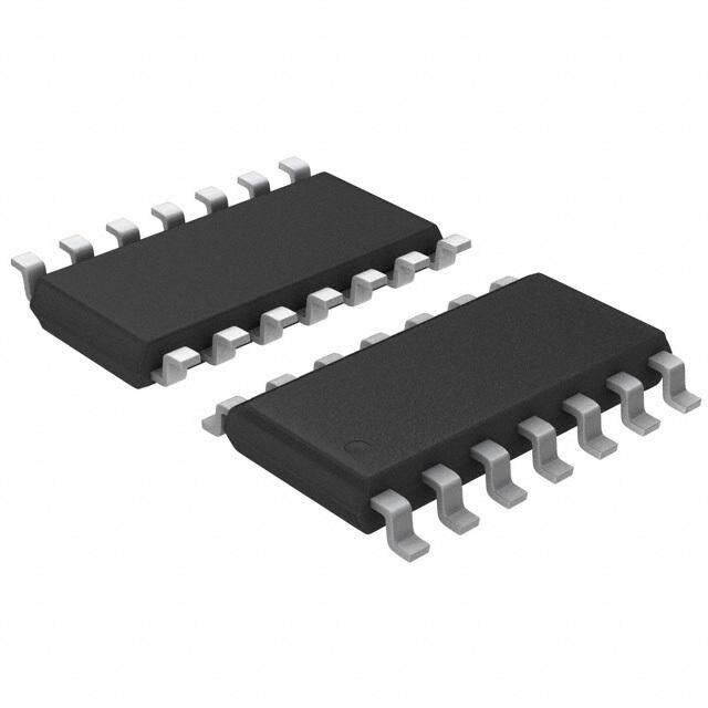
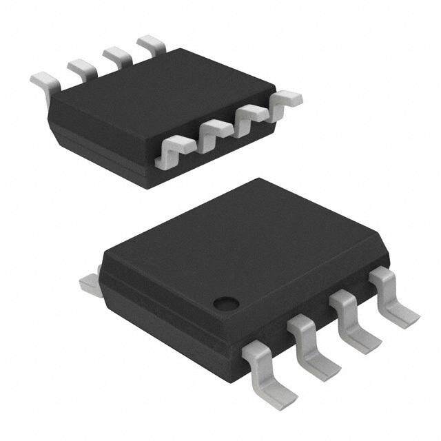
ICGOO在线商城 > 集成电路(IC) > PMIC - 稳压器 - DC DC 切换控制器 > UC3524N
- 型号: UC3524N
- 制造商: Texas Instruments
- 库位|库存: xxxx|xxxx
- 要求:
| 数量阶梯 | 香港交货 | 国内含税 |
| +xxxx | $xxxx | ¥xxxx |
查看当月历史价格
查看今年历史价格
UC3524N产品简介:
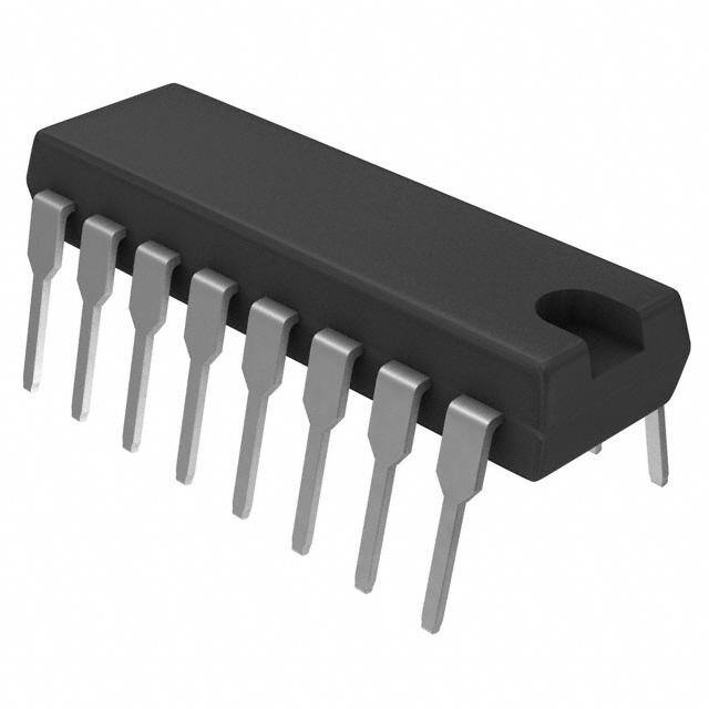
ICGOO电子元器件商城为您提供UC3524N由Texas Instruments设计生产,在icgoo商城现货销售,并且可以通过原厂、代理商等渠道进行代购。 UC3524N价格参考。Texas InstrumentsUC3524N封装/规格:PMIC - 稳压器 - DC DC 切换控制器, 升压,反激,正激转换器,全桥,半桥,推挽 稳压器 正 输出 升压,升压/降压 DC-DC 控制器 IC 16-PDIP。您可以下载UC3524N参考资料、Datasheet数据手册功能说明书,资料中有UC3524N 详细功能的应用电路图电压和使用方法及教程。
UC3524N 是德州仪器(Texas Instruments)推出的一款用于设计开关电源的PWM控制器。其主要应用场景包括以下几类:

 1. 开关电源适配器
   - UC3524N 可广泛应用于各种开关电源适配器中,例如笔记本电脑、手机充电器等设备的电源转换模块。它通过高效的PWM控制实现稳定的电压输出,满足设备对电能的需求。

 2. 工业电源
   - 在工业领域,UC3524N 常被用作DC-DC转换器的核心控制芯片,适用于电机驱动器、PLC(可编程逻辑控制器)、传感器供电等场景。它能够提供高精度的电压调节和电流保护功能,确保工业设备稳定运行。

 3. 通信设备
   - 该芯片适合于基站、路由器以及其他通信设备中的电源管理系统。这些设备通常需要多路电源输出,而UC3524N可以灵活配置,支持多种拓扑结构(如降压、升压或反激式转换),从而满足不同电路单元的供电需求。

 4. 汽车电子
   - 在车载电子系统中,UC3524N可用于电池管理、车灯控制以及信息娱乐系统的电源供应。它具备良好的抗干扰能力,能够在复杂的电磁环境中保持正常工作。

 5. 消费类电子产品
   - 包括家用电器(如电视、音响等)在内的许多消费类产品也采用UC3524N作为其内部电源管理方案的一部分。这有助于降低功耗并提高产品的整体性能。

总之,UC3524N凭借其高性能特性,在众多需要高效能量转换及精确控制的应用场合中发挥着重要作用。
| 参数 | 数值 |
| 产品目录 | 集成电路 (IC)半导体 |
| Cuk | 无 |
| 描述 | IC REG CTRLR BST FLYBK PWM 16DIP开关控制器 Adv Regulating PWM |
| 产品分类 | |
| 品牌 | Texas Instruments |
| 产品手册 | |
| 产品图片 |
|
| rohs | 符合RoHS无铅 / 符合限制有害物质指令(RoHS)规范要求 |
| 产品系列 | 电源管理 IC,开关控制器 ,Texas Instruments UC3524N- |
| 数据手册 | |
| 产品型号 | UC3524N |
| PWM类型 | 电压模式 |
| 上升时间 | 200 ns |
| 下降时间 | 100 ns |
| 产品目录页面 | |
| 产品种类 | 开关控制器 |
| 倍增器 | 无 |
| 其它名称 | 296-11214-5 |
| 分频器 | 无 |
| 包装 | 管件 |
| 升压 | 是 |
| 单位重量 | 1.054 g |
| 占空比 | 45% |
| 占空比-最大 | 50 % |
| 反向 | 无 |
| 反激式 | 是 |
| 同步管脚 | No |
| 商标 | Texas Instruments |
| 安装风格 | Through Hole |
| 封装 | Tube |
| 封装/外壳 | 16-DIP(0.300",7.62mm) |
| 封装/箱体 | PDIP-16 |
| 工作温度 | 0°C ~ 70°C |
| 工厂包装数量 | 25 |
| 开关频率 | 450 kHz |
| 拓扑结构 | Boost, Flyback, Forward, Full-Bridge, Half-Bridge, Push-Pull |
| 最大工作温度 | + 70 C |
| 最小工作温度 | 0 C |
| 标准包装 | 25 |
| 电压-电源 | 8 V ~ 40 V |
| 类型 | Voltage Mode PWM Controllers |
| 系列 | UC3524 |
| 输出数 | 2 |
| 输出电压 | 18 V |
| 输出电流 | 100 mA |
| 输出端数量 | 2 Output |
| 降压 | 无 |
| 隔离式 | 无 |
| 频率-最大值 | 300kHz |




- 商务部:美国ITC正式对集成电路等产品启动337调查
- 曝三星4nm工艺存在良率问题 高通将骁龙8 Gen1或转产台积电
- 太阳诱电将投资9.5亿元在常州建新厂生产MLCC 预计2023年完工
- 英特尔发布欧洲新工厂建设计划 深化IDM 2.0 战略
- 台积电先进制程称霸业界 有大客户加持明年业绩稳了
- 达到5530亿美元!SIA预计今年全球半导体销售额将创下新高
- 英特尔拟将自动驾驶子公司Mobileye上市 估值或超500亿美元
- 三星加码芯片和SET,合并消费电子和移动部门,撤换高东真等 CEO
- 三星电子宣布重大人事变动 还合并消费电子和移动部门
- 海关总署:前11个月进口集成电路产品价值2.52万亿元 增长14.8%





PDF Datasheet 数据手册内容提取
UC1524 UC2524 UC3524 www.ti.com SLUS180E–NOVEMBER1999–REVISEDOCTOBER2005 ADVANCED REGULATING PULSE WIDTH MODULATORS FEATURES DESCRIPTION • CompletePWMPowerControlCircuitry The UC1524, UC2524 and UC3524 incorporate on a • UncommittedOutputsforSingle-Endedor singlemonolithicchipallthefunctions required for the Push-PullApplications construction of regulating power supplies, inverters or switching regulators. They can also be used as the • LowStandbyCurrent...8mATypical control element for high-power-output applications. • InterchangeableWithSG1524,SG2524and The UC1524 family was designed for switching SG3524,Respectively regulators of either polarity, transformer-coupled dc-to-dc converters, transformerless voltage doublers and polarity converter applications employing fixed- frequency, pulse-width modulation techniques. The dual alternating outputs allow either single-ended or push-pull applications. Each device includes an on-chip reference, error amplifier, programmable oscillator, pulse-steering flip-flop, two uncommitted output transistors, a high-gain comparator, and current-limiting and shut-down circuitry. The UC1524 is characterized for operation over the full military temperature range of –55(cid:176) C to 125(cid:176) C. The UC2524 and UC3524 are designed for operation from –25(cid:176) C to85(cid:176) Cand0(cid:176) Cto70(cid:176) C,respectively. BLOCK DIAGRAM VREF OSC OUT 16 3 +5VTOALL VIN 15 REFERENCE INTERNAL +5V 12 CA Q RT 6 OSC R Q CT 7 11 EA (RAMP) 13 CB +5V +5V INV INPUT 1 ! COMPARATOR EA NI INPUT 2 + 14 EB GROUND 8 10k 5 !SENSE 1k C L 4 +SENSE 10 9 SHUTDOWN COMPENSATION Pleasebeawarethatanimportantnoticeconcerningavailability,standardwarranty,anduseincriticalapplicationsofTexas Instrumentssemiconductorproductsanddisclaimerstheretoappearsattheendofthisdatasheet. PRODUCTIONDATAinformationiscurrentasofpublicationdate. Copyright©1999–2005,TexasInstrumentsIncorporated Products conform to specifications per the terms of the Texas Instruments standard warranty. Production processing does not necessarilyincludetestingofallparameters.
UC1524 UC2524 UC3524 www.ti.com SLUS180E–NOVEMBER1999–REVISEDOCTOBER2005 CONNECTION DIAGRAM VREF VIN EB CB CA EA S/D COMP 16 15 14 13 12 11 10 9 REFERENCE REGULATOR S/D ERROR CURRENT AMP AMP ! + + ! OSCILLATOR 1 2 3 4 5 6 7 8 INV INPUT NIONNP UINTV OSC OUTSENCSLE(+) SENCSLE (!-) RT CT GND ABSOLUTE MAXIMUM RATINGS overoperatingfree-airtemperaturerange(unlessotherwisenoted) UNIT V Supplyvoltage(1)(2) 40V CC Collectoroutputcurrent 100mA Referenceoutputcurrent 50mA CurrentthroughC terminalg –50mA T T =25(cid:176) C(3) 1000mW A Powerdissipation T =25(cid:176) C(3) 2000mW C Operatingjunctiontemperaturerange –55(cid:176) Cto150(cid:176) C Storagetemperaturerange –65(cid:176) Cto+150(cid:176) C (1) Allvoltagevaluesarewithrespecttothegroundterminal,pin8. (2) Thereferenceregulatormaybebypassedforoperationfromafixed5VsupplybyconnectingtheV andreferenceoutputpinsbothto CC thesupplyvoltage.Inthisconfigurationthemaximumsupplyvoltageis6V. (3) Consultpackagingsectionofdatabookforthermallimitationsandconsiderationsofpackage. RECOMMENDED OPERATING CONDITIONS overoperatingfree-airtemperaturerange(unlessotherwisenoted) MIN NOM MAX UNIT V Supplyvoltage 8 40 V CC Referenceoutputcurrent 0 20 mA CurrentthroughC terminal –0.03 –2 mA T R Timingresistor 1.8 100 kW T C Timingcapacitor 0.001 0.1 m F T UC1524 –55 125 Operatingambienttemperaturerange UC2524 –25 85 (cid:176) C UC3524 0 70 2
UC1524 UC2524 UC3524 www.ti.com SLUS180E–NOVEMBER1999–REVISEDOCTOBER2005 ELECTRICAL CHARACTERISTICS thesespecificationsapplyforT =–55(cid:176) Cto125(cid:176) CfortheUC1524,–25(cid:176) Cto85(cid:176) CfortheUC2524,and0(cid:176) Cto70(cid:176) Cforthe A UC3524,V =20V,andf=20kHz,T =T,overoperatingfree-airtemperaturerange(unlessotherwisenoted) IN A J UC1524/UC2524 UC3524 PARAMETER TESTCONDITIONS UNIT MIN TYP MAX MIN TYP MAX REFERENCESECTION Outputvoltage 4.8 5.0 5.2 4.6 5.0 5.4 V Lineregulation V =8Vto40V 10 20 10 30 mV IN Loadregulation I =0mAto20mA 20 50 20 50 mV L Ripplerejection f=120Hz,T =25(cid:176) C 66 66 dB J Shortcircuitcurrentlimit V =0,T =25(cid:176) C 100 100 mA REF J Temperaturestability Overoperatingtemperaturerange 0.3% 1% 0.3% 1% Longtermstability T =125(cid:176) C,t=1000Hrs 20 20 mV J OSCILLATORSECTION Maximumfrequency C =1nF,R =2kW 300 300 kHz T T Initialaccuracy R andC constant 5% 5% T T Voltagestability V =8Vto40V,T =25(cid:176) C 1% 1% IN J Temperaturestability Overoperatingtemperaturerange 5% 5% Outputamplitude Pin3,T =25(cid:176) C 3.5 3.5 V J Outputpulsewidth C =0.01mfd,T =25(cid:176) C 0.5 0.5 m s T J ERRORAMPLIFIERSECTION Inputoffsetvoltage V =2.5V 0.5 5 2 10 mV CM Inputbiascurrent V =2.5V 2 10 2 10 m A CM Openloopvoltagegain 72 80 60 80 dB Commonmodevoltage T =25(cid:176) C 1.8 3.4 1.8 3.4 V J Commonmoderejectionratio T =25(cid:176) C 70 70 dB J Smallsignalbandwidth A =0dB,T =25(cid:176) C 3 3 MHz V J Outputvoltage T =25(cid:176) C 0.5 3.8 0.5 3.8 V J COMPARATORSECTION Duty-cycle %Eachoutputon 0% 45% 0% 45% Zeroduty-cycle 1 1 Inputthreshold V Maximumduty-cycle 3.5 3.5 Inputbiascurrent 1 1 m A CURRENTLIMITINGSECTION Sensevoltage Pin9=2Vwitherroramplifiersetfor 190 200 210 180 200 220 mV maximumout,T =25(cid:176) C J SensevoltageT.C. 0.2 0.2 mV/(cid:176) C T =–55(cid:176) Cto85(cid:176) Cforthe–1Vto1Vlimit –1 1 –1 1 J Commonmodevoltage V T =25(cid:176) C –0.3 1 J OUTPUTSECTION(EACHOUTPUT) Collector-emittervoltage 40 40 V Collectorleakagecurrent V =40V 0.1 50 0.1 50 m A CE Saturationvoltage I =50mA 1 2 1 2 V C Emitteroutputvoltage V =20V 17 18 17 18 V IN RiseTime R =2kW ,T =25(cid:176) C 0.2 0.2 m s C J FallTime R =2kW ,T =25(cid:176) C 0.1 0.1 m s C J Totalstandbycurrent(Note) V =40V 8 10 8 10 mA IN 3
UC1524 UC2524 UC3524 www.ti.com SLUS180E–NOVEMBER1999–REVISEDOCTOBER2005 PRINCIPLES OF OPERATION flip-flop, which is synchronously toggled by the The UC1524 is a fixed-frequency pulse-width-modu- oscillator output. The oscillator output pulse also lation voltage regulator control circuit. The regulator serves as a blanking pulse to assure both outputs are operates at a frequency that is programmed by one never on simultaneously during the transition times. timing resistor (R ), and one timing capacitor (C ), R T T T The width of the blanking pulse is controlled by the establishes a constant charging current for C . This T valve of C . The outputs may be applied in a results in a linear voltage ramp at C , which is fed to T T push-pull configuration in which their frequency is half the comparator providing linear control of the output that of the base oscillator Note that for buck regulator pulse width by the error amplifier. The UC1524 topologies, the two outputs can be wire-ORed for an contains an on-board 5 V regulator that serves as a effective 0-90% duty cycle range. With this reference as well as powering the UC1524’s internal connection, the output frequency is the same as the control circuitry and is also useful in supplying oscillator frequency. The output of the error amplifier external support functions. This reference voltage is shares a common input to the comparator with the lowered externally by a resistor divider to provide a current limiting and shutdown circuitry and can be reference within the common-mode range of the error overridden by signals from either of these inputs. This amplifier or an external reference may be used. The common point is also available externally and may be power supply output is sensed by a second resistor employed to control the gain of, or to compensate, divider network to generate a feedback signal to the the error amplifier or to provide additional control to error amplifier. The amplifier output voltage is then theregulator. compared to the linear voltage ramp at C . The T resulting modulated pulse out of the high-gain comparator is then steered to the appropriate output pass transistor (Q or Q ) by the pulse-steering 1 2 4
UC1524 UC2524 UC3524 www.ti.com SLUS180E–NOVEMBER1999–REVISEDOCTOBER2005 TYPICAL CHARACTERISTICS OPEN-LOOPVOLTRAGEAMPLIFICATION OSCILLATORFREQUENCY OFERRORAMPLIFIER vs vs TIMINGCOMPONENTS FREQUENCY 90 1 M RF= VIN= 20 V CT= 0.001mF VIN= 20 V dB 80 RF= 1M TJ= 25 C CT= 0.003mF TJ= 25 C ! 70 mplification 6500 RRFF== 310000 kk !uencyHz 100 k CT= 0.01mF geA 40 RF= 30 k Freq 10 k Volta 30 ator op 20 scil Lo Os 1 k CT= 0.003mF en- 10 RF is Resistance From p Pin 9 to Ground O 0 NOTE: Value of RFBelow 30 kW CT= 0.1mF Will Began to Limit Maximum Duty-Cycle !10 100 100 1 k 10 k 100 k 1 M 10 M 1 2 5 10 20 50 100 f!Frequency!Hz RT!Timing Resistor!kW Figure1. Figure2. OUTPUTDEADTIME OUTPUTSATURATIONVOLTAGE vs vs TIMINGCAPACITANCEVALUE LOADCURRENT 10 4 VIN= 20 V VCC= 20 V TJ= 25 C 3.5 4 V ! 3 s e (cid:181) g ! a e olt 2.5 ead Tim 1 mitter V 2 TJ= 25TCJ= 125 C D E Output 0.4 ctor-To- 1.5 TJ=!55C olle 1 C NOTE: Dead Time = Blanking Pulse Width 0.5 Plus Outplay Delay 0.1 0 0.001 0.004 0.01 0.04 0.1 0 20 40 60 80 100 CT!Capacitance! F Load Current!mA Figure3. Figure4. 5
UC1524 UC2524 UC3524 www.ti.com SLUS180E–NOVEMBER1999–REVISEDOCTOBER2005 APPLICATION INFORMATION OSCILLATOR SYNCHRONOUS OPERATIONS The oscillator controls the frequency of the UC1524 When an external clock is desired, a clock pulse of and is programmed by R and C according to the approximately 3 V can be applied directly to the T T approximateformula: oscillator output terminal. The impedance to ground 1.18 at this point is approximately 2 kW . In this f R C configuration R C must be selected for a clock T T (1) T T periodslightlygreaterthanthatoftheexternalclock. where If two or more UC1524 regulators are to operated RTisinkW synchronously, all oscillator output terminals should C isinm F be tied together, all C terminals connected to single T T fisinkHz timing capacitor, and the timing resistor connected to asingleR ,terminal. T Practical values of C fall between 1 nF and 100 nF. T Practical values of RT fall between 1.8 kW and 100 REF 16 kW . This results in a frequency range typically from 120Hzto500kHz. 1N916 COMP 9 5 k BLANKING The output pulse of the oscillator is used as a GND 8 blanking pulse at the output. This pulse width is Figure5.ErrorAmplifierClamp controlledbythevalueofC .If small values of C are T T required for frequency control, the oscillator output pulsewidthmaystillbeincreasedbyapplyinga shunt The other R terminals can be left open or shorted to T capacitance of up to 100 pF from pin 3 to ground. If V . Minimum lead lengths should be used between REF still greater dead-time is required, it should be theC terminals. T accomplished by limiting the maximum duty cycle by clamping the output of the error amplifier. This can easilybedonewiththecircuitinFigure5. V+ +28 V +5V, 5A 5 k PIC600 R2 5 k 15 1 12 5 k 2 11 500mF 0.1mF 5 k 16 13 3 k 6 UC1524 14 1.5 k 7 4 0.02 mF 3 5 10 9 0.001mF 9 50 k V! 0.1 Figure6.Single-EndedLCSwitchingRegulatorCircuit 6
UC1524 UC2524 UC3524 www.ti.com SLUS180E–NOVEMBER1999–REVISEDOCTOBER2005 V+ +28 V 15 5 k VIN 1 k 1 W UC1524 5 k 1 12 1 k INV INPUT CA 1 W 5 V 5 k 2 11 5 A NON INV INPUT EA 2N4150 5 k + 0.1mF 100 20T 5T 1500mF 16 13 VREF CB 100 20T 5T 2 k 6 14 RT EB 2N4150 0.1mF 7 4 CT CLSENSE(+) 0.1 k 3 5 OSC OUT CLSENSE(!) 0.001 mF 10 9 SD COMP 500mF GND 50 k 8 Figure7.Push-PullTransformerCoupledCircuit 2 k 2 k IS 1 W 1 W VIN 15 12 OUTPUT Osc. OUT 3 UC1524 13 11 VREF 16 4 8 6 7 2 1 9 10 4 5 N.I. INV. SHUT CURRENT RAMP INPUT INPUT COMP Down LIMET VIN 8-40 V 2 k 2 k 10 k 10 k 0.1 R1 C1 1 k 1 k Figure8.OpenLoopTestCircuit 7
PACKAGE OPTION ADDENDUM www.ti.com 17-Dec-2007 PACKAGING INFORMATION OrderableDevice Status(1) Package Package Pins Package EcoPlan(2) Lead/BallFinish MSLPeakTemp(3) Type Drawing Qty UC1524J OBSOLETE CDIP J 16 TBD CallTI CallTI UC1524J/80937 OBSOLETE CDIP J 16 TBD CallTI CallTI UC1524J883B OBSOLETE CDIP J 16 TBD CallTI CallTI UC2524DW ACTIVE SOIC DW 16 40 Green(RoHS& CUNIPDAU Level-2-260C-1YEAR noSb/Br) UC2524DWG4 ACTIVE SOIC DW 16 40 Green(RoHS& CUNIPDAU Level-2-260C-1YEAR noSb/Br) UC2524DWTR ACTIVE SOIC DW 16 2000 Green(RoHS& CUNIPDAU Level-2-260C-1YEAR noSb/Br) UC2524DWTRG4 ACTIVE SOIC DW 16 2000 Green(RoHS& CUNIPDAU Level-2-260C-1YEAR noSb/Br) UC2524J OBSOLETE CDIP J 16 TBD CallTI CallTI UC2524N ACTIVE PDIP N 16 25 Green(RoHS& CUNIPDAU N/AforPkgType noSb/Br) UC2524NG4 ACTIVE PDIP N 16 25 Green(RoHS& CUNIPDAU N/AforPkgType noSb/Br) UC3524D ACTIVE SOIC D 16 40 Green(RoHS& CallTI Level-2-260C-1YEAR noSb/Br) UC3524DG4 ACTIVE SOIC D 16 40 Green(RoHS& CallTI Level-2-260C-1YEAR noSb/Br) UC3524DTR ACTIVE SOIC D 16 2500 Green(RoHS& CallTI Level-2-260C-1YEAR noSb/Br) UC3524DTRG4 ACTIVE SOIC D 16 2500 Green(RoHS& CallTI Level-2-260C-1YEAR noSb/Br) UC3524DW ACTIVE SOIC DW 16 40 Green(RoHS& CUNIPDAU Level-2-260C-1YEAR noSb/Br) UC3524DWG4 ACTIVE SOIC DW 16 40 Green(RoHS& CUNIPDAU Level-2-260C-1YEAR noSb/Br) UC3524DWTR ACTIVE SOIC DW 16 2000 Green(RoHS& CUNIPDAU Level-2-260C-1YEAR noSb/Br) UC3524DWTRG4 ACTIVE SOIC DW 16 2000 Green(RoHS& CUNIPDAU Level-2-260C-1YEAR noSb/Br) UC3524J OBSOLETE CDIP J 16 TBD CallTI CallTI UC3524N ACTIVE PDIP N 16 25 Green(RoHS& CUNIPDAU N/AforPkgType noSb/Br) UC3524NG4 ACTIVE PDIP N 16 25 Green(RoHS& CUNIPDAU N/AforPkgType noSb/Br) (1)Themarketingstatusvaluesaredefinedasfollows: ACTIVE:Productdevicerecommendedfornewdesigns. LIFEBUY:TIhasannouncedthatthedevicewillbediscontinued,andalifetime-buyperiodisineffect. NRND:Notrecommendedfornewdesigns.Deviceisinproductiontosupportexistingcustomers,butTIdoesnotrecommendusingthispartin anewdesign. PREVIEW:Devicehasbeenannouncedbutisnotinproduction.Samplesmayormaynotbeavailable. OBSOLETE:TIhasdiscontinuedtheproductionofthedevice. (2)EcoPlan-Theplannedeco-friendlyclassification:Pb-Free(RoHS),Pb-Free(RoHSExempt),orGreen(RoHS&noSb/Br)-pleasecheck http://www.ti.com/productcontentforthelatestavailabilityinformationandadditionalproductcontentdetails. TBD:ThePb-Free/Greenconversionplanhasnotbeendefined. Pb-Free(RoHS):TI'sterms"Lead-Free"or"Pb-Free"meansemiconductorproductsthatarecompatiblewiththecurrentRoHSrequirements forall6substances,includingtherequirementthatleadnotexceed0.1%byweightinhomogeneousmaterials.Wheredesignedtobesoldered Addendum-Page1
PACKAGE OPTION ADDENDUM www.ti.com 17-Dec-2007 athightemperatures,TIPb-Freeproductsaresuitableforuseinspecifiedlead-freeprocesses. Pb-Free(RoHSExempt):ThiscomponenthasaRoHSexemptionforeither1)lead-basedflip-chipsolderbumpsusedbetweenthedieand package, or 2) lead-based die adhesive used between the die and leadframe. The component is otherwise considered Pb-Free (RoHS compatible)asdefinedabove. Green(RoHS&noSb/Br):TIdefines"Green"tomeanPb-Free(RoHScompatible),andfreeofBromine(Br)andAntimony(Sb)basedflame retardants(BrorSbdonotexceed0.1%byweightinhomogeneousmaterial) (3) MSL, Peak Temp. -- The Moisture Sensitivity Level rating according to the JEDEC industry standard classifications, and peak solder temperature. Important Information and Disclaimer:The information provided on this page represents TI's knowledge and belief as of the date that it is provided. TI bases its knowledge and belief on information provided by third parties, and makes no representation or warranty as to the accuracy of such information. Efforts are underway to better integrate information from third parties. TI has taken and continues to take reasonable steps to provide representative and accurate information but may not have conducted destructive testing or chemical analysis on incomingmaterialsandchemicals.TIandTIsuppliersconsidercertaininformationtobeproprietary,andthusCASnumbersandotherlimited informationmaynotbeavailableforrelease. InnoeventshallTI'sliabilityarisingoutofsuchinformationexceedthetotalpurchasepriceoftheTIpart(s)atissueinthisdocumentsoldbyTI toCustomeronanannualbasis. Addendum-Page2
PACKAGE MATERIALS INFORMATION www.ti.com 11-Mar-2008 TAPE AND REEL INFORMATION *Alldimensionsarenominal Device Package Package Pins SPQ Reel Reel A0(mm) B0(mm) K0(mm) P1 W Pin1 Type Drawing Diameter Width (mm) (mm) Quadrant (mm) W1(mm) UC2524DWTR SOIC DW 16 2000 330.0 16.4 10.85 10.8 2.7 12.0 16.0 Q1 UC3524DTR SOIC D 16 2500 330.0 16.4 6.5 10.3 2.1 8.0 16.0 Q1 UC3524DWTR SOIC DW 16 2000 330.0 16.4 10.85 10.8 2.7 12.0 16.0 Q1 PackMaterials-Page1
PACKAGE MATERIALS INFORMATION www.ti.com 11-Mar-2008 *Alldimensionsarenominal Device PackageType PackageDrawing Pins SPQ Length(mm) Width(mm) Height(mm) UC2524DWTR SOIC DW 16 2000 346.0 346.0 33.0 UC3524DTR SOIC D 16 2500 346.0 346.0 33.0 UC3524DWTR SOIC DW 16 2000 346.0 346.0 33.0 PackMaterials-Page2
None
None
None
None
IMPORTANTNOTICE TexasInstrumentsIncorporatedanditssubsidiaries(TI)reservetherighttomakecorrections,modifications,enhancements,improvements, andotherchangestoitsproductsandservicesatanytimeandtodiscontinueanyproductorservicewithoutnotice.Customersshould obtainthelatestrelevantinformationbeforeplacingordersandshouldverifythatsuchinformationiscurrentandcomplete.Allproductsare soldsubjecttoTI’stermsandconditionsofsalesuppliedatthetimeoforderacknowledgment. TIwarrantsperformanceofitshardwareproductstothespecificationsapplicableatthetimeofsaleinaccordancewithTI’sstandard warranty.TestingandotherqualitycontroltechniquesareusedtotheextentTIdeemsnecessarytosupportthiswarranty.Exceptwhere mandatedbygovernmentrequirements,testingofallparametersofeachproductisnotnecessarilyperformed. TIassumesnoliabilityforapplicationsassistanceorcustomerproductdesign.Customersareresponsiblefortheirproductsand applicationsusingTIcomponents.Tominimizetherisksassociatedwithcustomerproductsandapplications,customersshouldprovide adequatedesignandoperatingsafeguards. TIdoesnotwarrantorrepresentthatanylicense,eitherexpressorimplied,isgrantedunderanyTIpatentright,copyright,maskworkright, orotherTIintellectualpropertyrightrelatingtoanycombination,machine,orprocessinwhichTIproductsorservicesareused.Information publishedbyTIregardingthird-partyproductsorservicesdoesnotconstitutealicensefromTItousesuchproductsorservicesora warrantyorendorsementthereof.Useofsuchinformationmayrequirealicensefromathirdpartyunderthepatentsorotherintellectual propertyofthethirdparty,oralicensefromTIunderthepatentsorotherintellectualpropertyofTI. ReproductionofTIinformationinTIdatabooksordatasheetsispermissibleonlyifreproductioniswithoutalterationandisaccompanied byallassociatedwarranties,conditions,limitations,andnotices.Reproductionofthisinformationwithalterationisanunfairanddeceptive businesspractice.TIisnotresponsibleorliableforsuchaltereddocumentation.Informationofthirdpartiesmaybesubjecttoadditional restrictions. ResaleofTIproductsorserviceswithstatementsdifferentfromorbeyondtheparametersstatedbyTIforthatproductorservicevoidsall expressandanyimpliedwarrantiesfortheassociatedTIproductorserviceandisanunfairanddeceptivebusinesspractice.TIisnot responsibleorliableforanysuchstatements. TIproductsarenotauthorizedforuseinsafety-criticalapplications(suchaslifesupport)whereafailureoftheTIproductwouldreasonably beexpectedtocauseseverepersonalinjuryordeath,unlessofficersofthepartieshaveexecutedanagreementspecificallygoverning suchuse.Buyersrepresentthattheyhaveallnecessaryexpertiseinthesafetyandregulatoryramificationsoftheirapplications,and acknowledgeandagreethattheyaresolelyresponsibleforalllegal,regulatoryandsafety-relatedrequirementsconcerningtheirproducts andanyuseofTIproductsinsuchsafety-criticalapplications,notwithstandinganyapplications-relatedinformationorsupportthatmaybe providedbyTI.Further,BuyersmustfullyindemnifyTIanditsrepresentativesagainstanydamagesarisingoutoftheuseofTIproductsin suchsafety-criticalapplications. TIproductsareneitherdesignednorintendedforuseinmilitary/aerospaceapplicationsorenvironmentsunlesstheTIproductsare specificallydesignatedbyTIasmilitary-gradeor"enhancedplastic."OnlyproductsdesignatedbyTIasmilitary-grademeetmilitary specifications.BuyersacknowledgeandagreethatanysuchuseofTIproductswhichTIhasnotdesignatedasmilitary-gradeissolelyat theBuyer'srisk,andthattheyaresolelyresponsibleforcompliancewithalllegalandregulatoryrequirementsinconnectionwithsuchuse. TIproductsareneitherdesignednorintendedforuseinautomotiveapplicationsorenvironmentsunlessthespecificTIproductsare designatedbyTIascompliantwithISO/TS16949requirements.Buyersacknowledgeandagreethat,iftheyuseanynon-designated productsinautomotiveapplications,TIwillnotberesponsibleforanyfailuretomeetsuchrequirements. FollowingareURLswhereyoucanobtaininformationonotherTexasInstrumentsproductsandapplicationsolutions: Products Applications Amplifiers amplifier.ti.com Audio www.ti.com/audio DataConverters dataconverter.ti.com Automotive www.ti.com/automotive DSP dsp.ti.com Broadband www.ti.com/broadband ClocksandTimers www.ti.com/clocks DigitalControl www.ti.com/digitalcontrol Interface interface.ti.com Medical www.ti.com/medical Logic logic.ti.com Military www.ti.com/military PowerMgmt power.ti.com OpticalNetworking www.ti.com/opticalnetwork Microcontrollers microcontroller.ti.com Security www.ti.com/security RFID www.ti-rfid.com Telephony www.ti.com/telephony RF/IFandZigBee®Solutions www.ti.com/lprf Video&Imaging www.ti.com/video Wireless www.ti.com/wireless MailingAddress:TexasInstruments,PostOfficeBox655303,Dallas,Texas75265 Copyright©2008,TexasInstrumentsIncorporated
 Datasheet下载

