
 Datasheet下载
- 型号: UB16RKG035F-JB
- 制造商: NKK Switches
- 库位|库存: xxxx|xxxx
- 要求:
| 数量阶梯 | 香港交货 | 国内含税 |
| +xxxx | $xxxx | ¥xxxx |
查看当月历史价格
查看今年历史价格
UB16RKG035F-JB产品简介:
ICGOO电子元器件商城为您提供UB16RKG035F-JB由NKK Switches设计生产,在icgoo商城现货销售,并且可以通过原厂、代理商等渠道进行代购。 UB16RKG035F-JB价格参考。NKK SwitchesUB16RKG035F-JB封装/规格:按钮开关, 标准,发光式 按钮开关 SPDT 通孔。您可以下载UB16RKG035F-JB参考资料、Datasheet数据手册功能说明书,资料中有UB16RKG035F-JB 详细功能的应用电路图电压和使用方法及教程。
NKK Switches的UB16RKG035F-JB是一款按钮开关,广泛应用于需要可靠开关控制的各类电子和电气设备中。该型号具备紧凑设计与高耐用性,适合对空间和稳定性有要求的应用场景。

其主要应用场景包括:

1. 工业设备:用于控制面板、自动化设备、测试仪器等,实现启停或模式切换功能;
2. 医疗设备:如监护仪、诊断设备等,满足对安全性和稳定性的高标准;
3. 通信设备:适用于交换机、路由器等网络设备中的电源或功能控制;
4. 消费电子产品:如音响、家用电器等,提供用户操作界面的开关控制;
5. 交通运输设备:在车载控制系统、导航设备中用于功能选择或操作确认。

该开关具有良好的触感反馈与机械寿命,符合多种国际认证标准,适用于对品质和可靠性有较高要求的产品设计中。
| 参数 | 数值 |
| 产品目录 | |
| 描述 | SWITCH PUSH SPDT 0.4VA 28V |
| 产品分类 | |
| 品牌 | NKK Switches |
| 数据手册 | |
| 产品图片 |
|
| 产品型号 | UB16RKG035F-JB |
| PCN设计/规格 | |
| rohs | 无铅 / 符合限制有害物质指令(RoHS)规范要求 |
| RoHS指令信息 | |
| 产品系列 | UB |
| 产品培训模块 | http://www.digikey.cn/PTM/IndividualPTM.page?site=cn&lang=zhs&ptm=7079 |
| 侵入防护 | - |
| 其它名称 | UB16RKG035FJB |
| 包装 | 散装 |
| 安装类型 | 通孔 |
| 工作温度 | -25°C ~ 50°C |
| 开关功能 | 开-开 |
| 机械寿命 | 200,000 次循环 |
| 标准包装 | 1 |
| 照明电压(标称值) | 2.1 VDC |
| 照明类型,颜色 | LED,绿 |
| 特性 | 环氧树脂密封端子 |
| 电气寿命 | 200,000 次循环 |
| 电路 | SPDT |
| 相关产品 | /product-detail/zh/AT4174/AT4174-ND/2103760 |
| 端子类型 | PC 引脚 |
| 类型 | 标准,发光式 |
| 致动器类型 | 矩形,按钮 |
| 面板开口尺寸 | - |
| 颜色-致动器/盖帽 | 透明(白色滤色镱/漫射器) |
| 额定电压-AC | 28V |
| 额定电压-DC | 28V |
| 额定电流 | 0.4VA(AC/DC) |


- 商务部:美国ITC正式对集成电路等产品启动337调查
- 曝三星4nm工艺存在良率问题 高通将骁龙8 Gen1或转产台积电
- 太阳诱电将投资9.5亿元在常州建新厂生产MLCC 预计2023年完工
- 英特尔发布欧洲新工厂建设计划 深化IDM 2.0 战略
- 台积电先进制程称霸业界 有大客户加持明年业绩稳了
- 达到5530亿美元!SIA预计今年全球半导体销售额将创下新高
- 英特尔拟将自动驾驶子公司Mobileye上市 估值或超500亿美元
- 三星加码芯片和SET,合并消费电子和移动部门,撤换高东真等 CEO
- 三星电子宣布重大人事变动 还合并消费电子和移动部门
- 海关总署:前11个月进口集成电路产品价值2.52万亿元 增长14.8%


PDF Datasheet 数据手册内容提取
Series UB Low Profile Pushbuttons s e gl General Specifications g o T s er Electrical Capacity (Resistive Load) k c o Power Level (silver): 5A @ 125/250V AC or 5A @ 30V DC R Logic Level (gold): 0.4VA maximum @ 28V AC/DC maximum (Applicable Range 0.1mA ~ 0.1A @ 20mV ~ 28V) s n o Note: Find additional explanation of operating range in Supplement section. utt b sh Other Ratings u P Contact Resistance: 50 milliohms maximum for silver; 100 milliohms maximum for gold B P Insulation Resistance: 200 megohms minimum @ 500V DC d ateD Dielectric Strength: 1,000V AC minimum between contacts for 1 minute minimum; min 1,500V AC minimum between contacts & case for 1 minute minimum Illu Mechanical Life: 1,000,000 operations minimum for momentary; e 200,000 operations minimum for alternate action bl a Electrical Life: 10,000 operations minimum for silver; m am 100,000 operations minimum for silver with resistive load of 3A @ 125V AC ogr 200,000 operations minimum for gold Pr Nominal Operating Force: Single Pole: 1.9N for Square & 1.9N for Rectangular s Double Pole: 2.55N for Square & 3.1N for Rectangular k oc Contact Timing: Break before make yl e Travel: Pretravel .067” (1.7mm); Overtravel .024” (0.6mm); Total Travel .091” (2.3mm) K Materials & Finishes s Housing/Bezel: Glass fiber reinforced polyamide (UL94V-0) e ari Snap-in Frame: Stainless steel ot R Movable Contactor: Phosphor bronze Movable Contacts: Silver alloy or copper with gold plating Stationary Contacts: Silver alloy or copper with gold plating es Switch Terminals: Phosphor bronze with silver or gold plating d Sli Lamp Terminals: Brass with silver plating Base: Glass fiber reinforced liquid crystal polymer (UL94V-0) Environmental Data s e ctil Operating Temperature Range: –25°C through +50°C (–13°F through +122°F) for Illuminated a T –20°C through +70°C (–4°F through +158°F) for Nonilluminated Humidity: 90 ~ 95% humidity for 96 hours @ 40°C (104°F) Vibration: 10 ~ 55Hz with peak-to-peak amplitude of 1.5mm traversing the frequency range & returning Tilt Shock: 5in0 1G m(4in9u0tem;/ 3s 2r)i gahcct ealnegraletido nd i(rteecstteiodn sin f o6r r2ig hhot uarnsgled directions, with 5 shocks in each direction) Installation Cap Installation Force: 7.55N (1.70 lbf) maximum downward force on cap h uc Soldering Time & Temp: Wave Soldering (PC version): See Profile A in Supplement section. o T Manual Soldering: See Profile A in Supplement section. Cleaning: These devices are not process sealed. Hand clean locally using alcohol based solution. s or Standards & Certifications at c Flammability Standards: UL94V-0 housing/bezel & base di In UL: File No. E44145 - Recognized only when ordered with marking on switch. Add “/U” or “/CUL” before dash in part number to order UL recognized switch. s orie UL recognized only when ordered switch body with cap assembled. s All single & double pole models recognized at 5A @ 125/250V AC or 0.014A @ 28V DC. s e cc CSA: File No. 023535_0_000 - Certified only when ordered with marking on switch. A Add “/C” before dash in part number to order CSA certified switch. nt All single & double pole models certified at 5A @ 125/250V AC or 5A @ 30V DC or e m 0.4VA maximum @ 28V AC/DC maximum. e pl p u S D80 www.nkkswitches.com 11/12/18
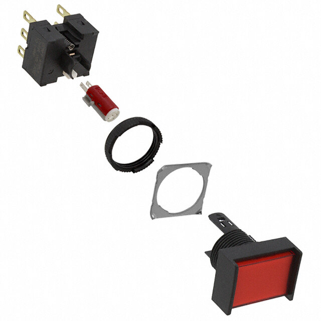
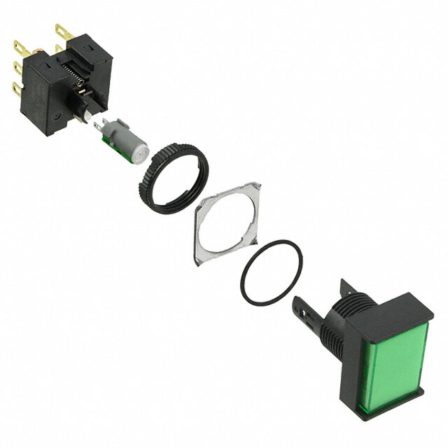
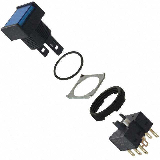
Series UB Low Profile Pushbuttons s e Distinctive Characteristics gl g o T s Red/green and amber/blue bicolors with alternating standard or custom legends. er k c Super bright LED provides brilliant uniform illumination. o R s n o Bright or super bright LEDs (an integral part of the switch) of red, utt b h amber, green, blue, or white, in full face or spot illumination s u P plus square or rectangular models. B P d e D at n mi Combination of PCB mountability and short body u Ill allows use in compact applications. e bl a m m a gr o Small behind panel dimension for snap-in Pr mounting in tight spaces. s k c o yl e K Snap-acting contact mechanism provides sensitive actuation with audible feedback; s e quick-make, quick-break characteristic ari ot limits arcing and prolongs electrical life. R s e d Latchdown mechanism, independent of switching Sli mechanism, gives visible and tactile indication of circuit status. s e ctil a T Terminals are epoxy sealed to lock out flux, solvents, and other contaminants. Tilt Momentary and alternate action circuits available in the same space-saving body size. h c u o T Matching indicators available. Actual Size s or at c di n I s e ori s s e c c A nt e m e pl p u S www.nkkswitches.com D81
Series UB Low Profile Pushbuttons s e gl TYPICAL SWITCH ORDERING EXAMPLE g o T UB 1 5 SK G 03 s er k c o R s Poles n o butt 1 SPDT Circuits Terminals ush 2 DPDT Solder Lug P 5 ON (ON) Mounting Types Contacts & Ratings 01 (for Snap-in d PB ( ) = Momentary PCB Mounting W Silver Rated 5A Mounting) ateD 6 ON ON SK Square @ 125/250V AC 03 Straight PC n Illumi Awlittehr nLaattech Adcotwionn RK Rectangular G G@o 2ld8 RVa AtedC /0D.4CV Am maxax e * Snap-in Mounting bl a m KK Square m a gr NK Rectangular o Pr Rectangular with NBK s Side Barriers k c ylo * Standard with e K Solder Lug terminals s e ari ot R IMPORTANT: s Switches are supplied without UL, cULus & e d CSA marking unless specified. UL, cULus & Sli CSA recognized only when ordered with marking on the switch. Specific models, ratings, & ordering instructions are noted s on General Specifications page. e ctil a T Tilt h DESCRIPTION FOR TYPICAL ORDERING EXAMPLE c u o T UB15SKG035C-CC s or at Red, Bright LED & Red Lens c Gold Contacts with di with Red Diffuser n 0.4VA Rating I Square SPDT ON-(ON) Circuit s orie with PCB Mounting Straight PC Terminals s s e c c A nt e m e pl p u S D82 www.nkkswitches.com
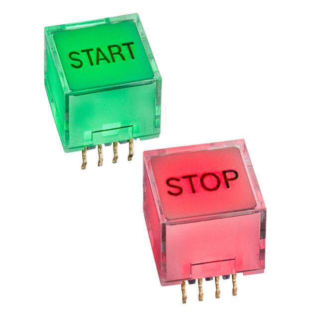
Series UB Low Profile Pushbuttons s e TYPICAL SWITCH ORDERING EXAMPLE gl g o T 5C CC s er k c o R LEDS Cap Types & Colors Bright LED Full Face Illuminated Cap ns o 5C Red for Bright LED butt h Lens/Diffuser Colors s 5D Amber Pu CB Red/White FF Green/Green 5F Green PB CC Red/Red *FJ Green/Clear ed D at *CJ Red/Clear JB Clear/White min u DB Amber/White JC Clear/Red Ill e DD Amber/Amber JD Clear/Amber abl m m *DJ Amber/Clear JF Clear/Green a gr FB Green/White *JJ Clear/Clear Pro Square & Rectangular Spot Illumi- AB s nated Black Cap with White Window ck o yl * Not available with Rectangular cap e K Super Bright LED Full Face Illuminated Cap s for Super Bright LED e 6B White ari JB Clear Lens/White Diffuser ot 6F Green R Spot Illuminated Black Cap 6G Blue AB with White Window s e d Super Bright Bicolor LED Alternating Legend Cap/Diffuser Alternating Legends Sli 6CF Red/Green JCF Red/Green 11 ON (pos) OFF (pos) 6DG Amber/Blue JDG Amber/Blue 12 ON (neg) OFF (neg) s e 13 START STOP ctil a Nonilluminated Nonilluminated Cap Colors T 14 OPEN CLOSE N Nonilluminated A Black E Yellow B White F Green C Red G Blue Tilt h c u o T Part Numbers for Alternating Legends s or Square Alternating Legends Rectangular Alternating Legends at c di Color Part Number Color Part Number Color Part Number Color Part Number n I AT9450CF11 AT9450DG11 AT9451CF11 AT9451DG11 s e AT9450CF12 Amber/ AT9450DG12 AT9451CF12 Amber/ AT9451DG12 ori Red/Green Red/Green s AT9450CF13 Blue AT9450DG13 AT9451CF13 Blue AT9451DG13 es c c A AT9450CF14 AT9450DG14 AT9451CF14 AT9451DG14 nt Refer to Ordering Table for Alternating Legend that corresponds with last 2 digits of part number. e m e pl p u S www.nkkswitches.com D83
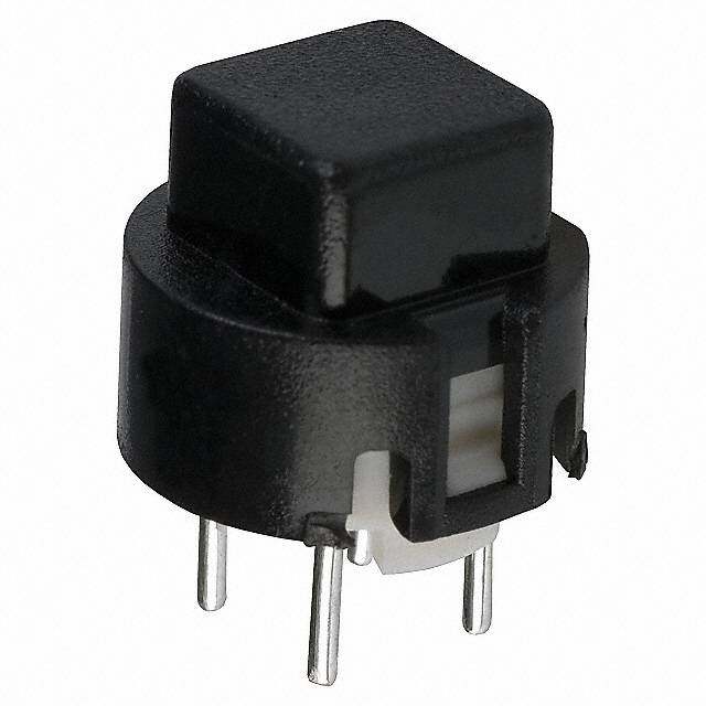
Series UB Low Profile Pushbuttons s e gl POLES & CIRCUITS g o T Plunger Position ( ) = Momentary Connected Terminals Throw & Switch/Lamp Schematics s er k Normal Down Normal Down Notes: Switch is marked with NC, NO, COM, L+ & L–. c Ro Pole Model Lamp circuit is isolated and requires an external power source. s n 1 COM o UB15 ON (ON) hbutt SP *UB16 ON ON 1-3 1-2 SPDT 3 NC 2 NO (+) (-) s u P UB25 ON (ON) 1 COM 4 COM d PB DP *UB26 ON ON 1-3 4-6 1-2 4-5 DPDT 3 NC 2 NO 6 NC 5 NO (+) (-) e atD min * When in latchdown position for the alternate circuit, cap position is .039” (1.0mm) above the housing. u Ill e MOUNTING TYPES & SHAPES bl a m m a PCB Mounting gr o Pr (5.08) (2.54) Typ (5.08) Typ (2.54) Typ (7.62) (2.54) Typ (7.62) Typ (2.54) Typ SK .200 .100 .200 .100 RK .300 .100 .300 .100 Square 3 6 3 Rectangular 3 6 3 ks L + L + L + L + oc 2 (10.16) 5 2 (10.16) 2 (10.16) 5 2 (10.16) yl L - .400 L - .400 L - .400 L - .400 Ke 1 4 1 1 4 1 (1.2) Dia Typ (1.2) Dia Typ (1.2) Dia Typ (1.2) Dia Typ CL .047 CL .047 CL .047 CL .047 es Single Pole Double Pole Single Pole Double Pole ari ot R Snap-in Mounting (Solder Lug) Square Rectangular Rectangular with Built-in es KK NK NBK d with Built-in Bezel with Built-in Bezel Side Barriers Sli (16.2) .638 es (16.2) Sq ctil .638 a T (22.4) .882 Snap-in Mounting with Solder Lug terminals is the standard combination. Panel Thickness: .039 ~ .126” (1.0 ~ 3.2mm) Tilt CONTACT MATERIALS & RATINGS h W c Silver Contacts Power Level 5A @ 125V AC & 250V AC u o T G s Gold Contacts Logic Level 0.4VA maximum @ 28V AC/DC maximum or at dic Complete explanation of operating range in Supplement section. n I TERMINALS s e ori s (0.2) Acces 01 Solder Lug (1.6) .008(.519.07) 03 Straight PC .(000.28()4.0) .063 (2.0) .157 ent (0.8) .079 .(01.309) em .032 Thk = (0.5) pl Thk = (0.5) .020 p .020 u S D84 www.nkkswitches.com
Series UB Low Profile Pushbuttons s e BRIGHT & SUPER BRIGHT LED COLORS & SPECIFICATIONS gl g o T The electrical specifications shown are determined at a basic temperature of 25°C. LED circuit is isolated and requires external power source. Polarity marks are on bottom of switch. If the source voltage exceeds the rated voltage, a ballast resistor is required. Resistor value can be calculated by using the formula in the Supplement section. LED is an integral part of switch and not available separately. s er k Super Bright LEDs are ATTENTION Bright Super Bright oc R Electrostatic Sensitive ELECTROSTATIC SENSITIVE DEVICES 5C 5D 5F 6B 6F 6G s (+) (-) Color Red Amber Green White Green Blue Unit on utt Maximum Forward Current I 30 30 25 20 30 30 mA hb FM s u Typical Forward Current I 20 20 20 15 20 20 mA P F B Forward Voltage VF 1.85 2.0 2.1 3.3 3.2 2.9 V ed P Maximum Reverse Voltage V 5 5 5 5 5 5 V D nat RM mi Current Reduction Rate Above 25°C ∆IF 0.40 0.42 0.46 0.25 0.40 0.33 mA/°C Illu Ambient Temperature Range –25° ~ +50°C –25° ~ +50°C ble a m m N a No Lamp gr o Pr CAP TYPES & COLOR COMBINATIONS s k c o Full Face Illuminated Cap for Bright LED & Super Bright Single Color LED yl e K Lens/Diffuser Lens/Diffuser Colors Available for Square Cap: Colors Available for Rectangular Cap: s e CB DD FJ JF ALeTn4s074 (.311.08) CB FB JD ALeTn4s117 (.311.08) otari (12.0) Sq (12.0) (17.0) R CC DJ JB JJ .472 CC FF JF .472 .669 CJ FB JC AT4075 DB JB AT4118 (0.5) es Diffuser .(002.50) Diffuser .020 Slid (15.35) DB FF JD ( 1.400.375) Sq DD JC ( 1.400.375) .604 Lens & Diffuser Material: Polycarbonate Lens Finish: Glossy Diffuser Finish: Textured s e Spot Illuminated Caps for Bright & Super Bright LEDs ctil a T Cap/Window Colors Available: (1.9) .(01.795) .075 (3.1) Black Cap with AT4119 Square (3.1) AT4120 Rectangular .122 AB (5.0) .122 (5.0) Tforar nLsElDuc Denistp Wlayhite Window fSourp Berri gBhritg ahnt dL ED .197 (3.0) fSourp Berri gBhritg ahnt dL ED .197 (.311.08) Tilt .118 (12.0) Sq (12.0) (17.0) Material: Polycarbonate Finish: Matte .472 .472 .669 Full Face Illuminated Caps for Super Bright Bicolor LED h c JB u (3.0) o (3.0) .118 T .118 AT4074 Square Lens ( 1.427.02) Sq AT4117 Rectangular Lens (.1427.02) (.1676.09) (0.5) (0.5) .020 s AT4188 Square Diffuser ( 1.400.375.) 0S2q0 AT4189 Rectangular Diffuser ( 1.400.375) ( 1.650.345) dicator n Lens & Diffuser Material: Polycarbonate Lens Finish: Glossy Diffuser Finish: Textured I Cap Colors Available: Opaque Caps for Nonilluminated ories s s A C F AT4073 AT4116 (3.0) cce Square (3.0) Rectangular .118 A B E G MFinaitsehr:i a lG: l oPsoslyycarbonate .(1427.20) Sq.118 (.1427.20) (.1676.09) ent m e Color Codes: A Black B White C Red D Amber E Yellow F Green G Blue J Clear ppl u S www.nkkswitches.com D85
Series UB Low Profile Pushbuttons s e gl SUPER BRIGHT BICOLOR LEDS FOR ALTERNATING LEGENDS g o T The electrical specifications shown are determined at a basic temperature of 25°C. LED circuit is isolated and requires external power source. Polarity marks are on bottom of switch. If the source voltage exceeds the rated voltage, a ballast resistor is required. Resistor s er value can be calculated by using the formula in the Supplement section. LED is an integral part of switch and not available separately. k c o R Electrical Specifications for Super Bright Bicolor LEDs s n o hbutt SLEuDpse ra Breri g ht SEENLASETCITTTIEVRNEO TSDITOEAVTNIICCES 6CF Red/Green 6DG Amber/Blue s u P Electrostatic Sensitive Color Red Green Amber Blue Unit B P d Maximum Forward Current I * 30 * 30 * 30 * 30 mA e FM atD min Typical Forward Current IF 20 20 20 20 mA u Ill Forward Voltage V 2.3 3.2 2.1 3.0 V e F bl ma Maximum Reverse Voltage V 4 4 4 4 V m RM a gr Current Reduction Rate Above 25°C ∆I 0.33 0.33 0.33 0.33 mA/°C o F Pr Ambient Temperature Range –25° ~ +50° –25° ~ +50° °C s ck * Value applies to single color illumination for either Red or Green or Amber or Blue. When both colors are illuminated simultaneously, o yl the sum of the currents should not exceed the smallest value of the maximum forward current. e K Super Bright Bicolor L1 (-) Super Bright Bicolor L1 (-) Red Amber es Red/Green LED LC (+) Amber/Blue LED LC (+) otari with 2 elements LG2r e(-e)n with 2 elements LB2lu (e-) R Alternating Legend Caps for Super Bright Bicolor LED s e d Sli JCF JDG JCF JDG (3.0) .118 es AT4074 12.0mm Square (.311.08) AT4117 12.0mm x 17.0mm (.1427.02) (.1676.09) ctil Flat Cap ( 1.427.02) Sq Rectangular Flat Cap a T AT9450 Square AT9451 Rectangular Legend Insert Legend Insert Tilt Diffuser AT4188 Square Diffuser AT4189 Rectangular Diffuser h Lens & Diffuser Material: Polycarbonate Legend Insert Material: Polyethylene Terephthalate (PET) c u To Lens Finish: Glossy Diffuser Finish: Textured s Standard Alternating Legend Pairs or at c ndi 11 12 13 14 I ON OFF ON OFF START STOP OPEN CLOSE s e ori s es Green/Red or Blue/Amber Green/Red or Blue/Amber Green/Red or Blue/Amber Green/Red or Blue/Amber c c A nt Cap illumination is alternating Green/Red or Blue/Amber; legend text is black. e m Contact factory for other Alternating Legends. e pl p Legend illustrations are approximate representations of the actual characters on the filters. u S D86 www.nkkswitches.com
Series UB Low Profile Pushbuttons s e TYPICAL SWITCH DIMENSIONS gl g o T Single & Double Pole Square • PCB Mount (0.5) .020 s er N.C3. L + 6N.C. (5.08) Typ ock (12.0) Sq .200 R .472 2 5 NCO.OM. NCO.OM. (2.5) (.00.250) Typ 1 L - 4 (1.0( )2 .T1.y05p04) Typ uttons .098 .039 b (15.24) Sq (1.0) (10.0) (4.0) (5.08) Typ sh .600 .039 .394 .157 .200 u P Latchdown Position B Single pole models do not have terminals 4, 5, & 6. UB15SKG035C-CB d P e Single & Double Pole Rectangular • PCB Mount D nat mi (0.5) u .020 Ill e (.1427.20) N.C32. L + 56N.C. .(52.0008) Typ mmabl ( 1.650.204) NCO.OM1.. L - 4NCO.OM. ( 2.1.0504) Typ ogra (0.5) Typ Pr (17.0) (2.5) .020 .669 .098 (20.32) (1.0) (10.0) (4.0) (7.62) Typ (1.0) Typ ks .800 .039 .394 .157 .300 .039 oc Latchdown Position yl e Single pole models do not have terminals 4, 5, & 6. UB26RKG035D-DD K Single & Double Pole Square • Snap-in Mount • Built-in Bezel s e .(015.45) (.00.382) xx .(01.663) Typ ari ot R 3 L + 6 N.C. N.C. (5.08) Typ (12.0) Sq .200 (15.8) .472 2 5 .622 NCO.OM. NCO.OM. (2.54) Typ s 1 L - 4 .100 de (.00.250) Typ Sli (2.5) (2.0) Typ .098 .079 (17.8) Sq (1.0) (10.0) (5.0) (5.08) Typ .701 .039 .394 .197 .200 Latchdown Position es Single pole models do not have terminals 4, 5, & 6. UB25KKW015C-CB ctil a T Single & Double Pole Rectangular • Snap-in Mount • Built-in Bezel (1.4) (0.8) x (1.6) Typ .055 .032 x .063 (17.8(.)1427.20) N.C32. L + 56N.C. (.52.0008) Typ(.1652.28) Tilt .701 NCO.OM.. NCO.OM. (2.54) Typ 1 L - 4 .100 (0.5) Typ h .020 c (.1676.09) (.20.958) (.73.0602) Typ (.20.709) Typ Tou (24.0) (1.0) (10.0) (5.0) (22.0) .945 .039 .394 .197 .866 Latchdown Position s Single pole models do not have terminals 4, 5, & 6. UB26NKW015F-FF or at c Single & Double Pole Rectangular • Snap-in Mount • Built-in Side Barriers di n I (0.8) x (1.6) Typ .032 x .063 s ( 1.770.81)(.1427.20) NCNO.O.CM132... LL -+ 456NCNO.O.CM.. ( 2( .5.12.0.5000480) ) TTyypp.(1652.28) Accessorie (0.5) Typ .020 (17.0) (7.62) Typ (2.0) Typ nt .669 ( 2.944.05) (.315.94) .(83.369) (.519.07) .300 ( 2.826.06) .079 pleme Single pole models do not have terminals 4, 5, & 6. UB25NBKW015F-FB up S www.nkkswitches.com D87
Series UB Low Profile Pushbuttons s e gl TYPICAL SWITCH DIMENSIONS g o T Square • PCB Mount (0.5) (5.08) Typ (2.54) Typ .020 .200 .100 6 3 ers (5.08) Typ N.C3. L C 6 LC Rock (.1427.20) Sq .200 NCO.OM2. L 2 5 ( 5.2.0080) 5 L2 L1 2 ( 1.400.106) 1 L 1 4 4 1 (2.54) Typ (1.0) Typ ns (2.5) (.00.250) Typ .100 (1.0) Typ (1.27) Typ.039 (2.1.0504) CL .(014.27) Dia Typ o .098 .039 .50 utt (15.24) Sq (1.0) (10.0) (4.0) (5.08) Typ b .600 .039 .394 .157 .200 h us Latchdown Position P UB25SKG036DG-JDG11 Single pole models do not have terminals 4, 5, & 6. B P d nateD Square • Snap-in Mount • Built-in Bezel (1.4) (0.8) x (1.6) Typ mi .055 .032 x .063 u Ill 3 L C 6 e (5.08) Typ N.C. N.C. (15.8) bl (12.0) Sq .200 (5.08).622 (16.2) Sq ogramma .472 (.00.250) Typ ( 2.1.0504) Typ NCO.OM21. L L2 1 45NCO.OM. ( 1.2.00) 0Typ .638 Pr (2.5) (4.0) (2.0) Typ (1.27) Typ .039 .098 .157 .079 .50 ks (.1770.18) Sq .(013.09) (.1309.40) (.519.07) ( 5.2.0080) Typ c ylo Latchdown Position Panel Thickness: Ke UB25KKW016DG-JDG11 Single pole models do not have terminals 4, 5, & 6. (1.0 ~ 3.2mm) .039 ~ .126” Rectangular • PCB Mount (0.5) (7.62) Typ (2.54) Typ es .020 .300 .100 Rotari ( 1.650.204(.)1427.20) ( 5.2.0080) Typ NCNO.O.CM132... L 1 L C L 2 456NCNO.O.CM.. ( 5.2.0080) 465 L2 LLC1 132 ( 1.400.106) (2.54) Typ (1.0) Typ des (.1676.09) (2.5) (.00.250) Typ .100 (1.0) Typ (1.27) Typ .039 (2.1.0504) CL . 0(14.27) Dia Typ Sli ( 2.800.302) .0 9(18.0) (10.0) (4.0) .039 (7.62) Typ .050 .039 .394 .157 .300 Latchdown Position UB25RKG036DG-JDG11 Single pole models do not have terminals 4, 5, & 6. s e actil Rectangular • Snap-in Mount • Built-in Bezel T (1.4) (0.8) x (1.6) Typ (22.0) .055 .032 x .063 .866 Tilt (17.8(.)1427.20) ( 5.2.0080) Typ N.C32. L C 56N.C. ( 5.2.0080)(.1652.28) (.1663.82) .701 NCO.OM.. L 1 L 2 NCO.OM. 1 4 (0.5) Typ (2.54) Typ .020 .100 (17.0) (2.5) (4.0) (2.0) (1.27) Typ (1.0) Typ (22.4) h .669 .098 .157 .079 .050 .039 .882 uc (24.0) (1.0) (10.0) (5.0) (7.62) Typ To .945 .039 .394 .197 .300 Latchdown Position Panel Thickness: UB26NKW016DG-JDG11 Single pole models do not have terminals 4, 5, & 6. (1.0 ~ 3.2mm) .039 ~ .126” s or at Rectangular • Snap-in Mount • Built-in Side Barriers ndic (.00.382) xx .(01.663) Typ ( 2.826.06) I essories ( 1.770.81)(.1427.20) ( 5.2.0080) Typ NCNO.O.CM132... L 1 L C L 2 456NCNO.O.CM.. ( 5.2.0080)(.1652.28) (.1663.82) c (0.5) Typ (2.54) Typ Ac .020 .100 (17.0) (4.0) (2.0) (1.27) Typ (1.0) Typ (22.4) nt .669 (24.0) (3.9) (8.6) (5.0) .157 .079 (7.62) Typ .050 .039 .882 me .945 .154 .339 .197 .300 Panel Thickness: e pl UB26NBKW016DG-JDG11 Single pole models do not have terminals 4, 5, & 6. (1.0 ~ 3.2mm) .039 ~ .126” p u S D88 www.nkkswitches.com
Series UB Low Profile Pushbuttons s e OPTIONAL ACCESSORIES gl g o T Spring Loaded Protective Guard for Snap-in Mounting of Square PCB Model s AT4173 er k Square Protective Guard/ oc Snap-in Frame (10.5) R .413 (15.64) Opens 180° (20.5) .616 ons Closes automatically .807 utt b h s u Materials: (18.4) P Cover: Clear Polycarbonate .724 (20.4) (6.0) (9.0) (15.64) PB Base: Black Polyamide .803 .236 .354 .616 d e Coil Spring: Stainless Steel D at n 180° mi u Recommended Ill Panel Thickness: ( 1.781.72) Sq ble .039” ~ .126” ma m (1.0mm ~ 3.2mm) a (39.0) Min* Protective gr Recommended AT4173 1.535 Guard Pro 2 Panel-to-PCB Range: (10.5) Panel s .354” ~ .433” .413 ck o (9.0mm ~ 11.0mm) (2.800.57) Installation Keyl 1 Install switch onto 3 Switch PC board. .(395.04) ~~ (.1413.03) (2.800.43) ( 2.800.43) (N) 2 3 SgJonuiaanpr dt hp eirn ottwote ocptaivneel. 1 PC Board Rotaries assemblies. (N) = Number of switches * Minimum dimension allows opening of cover to 180° s e d Spring Loaded Protective Guard for Square Snap-in Model Sli AT4171 es Square ctil a T Protective Guard (10.5) .413 (17.9) Opens 180° .705 Closes automatically (2.800.57) .(278.10) Tilt Cap Height (18.4) When (14.2) .724 Assembled .559 (20.4) (7.5) (17.9) (16.2) Sq .803 .295 .705 ch .638 u o T (39.0) Min* 1.535 AT4171 s or (10.5) 180° cat .413 di Materials: n I (20.5) Cover: Clear Polycarbonate .807 Base: Black GFR Polyamide s e Coil Spring: Stainless Steel ori s s (20.4) e .803 Recommended Panel Thickness: Acc (20.4) .803 (N) .039” ~ .106” (1.0mm ~ 2.7mm) (N) = Number of switches * Minimum dimension allows opening of cover to 180° ent m e pl p u S www.nkkswitches.com D89
Series UB Low Profile Pushbuttons s e gl OPTIONAL ACCESSORIES g o T Spring Loaded Protective Guard for Snap-in Mounting of Rectangular PCB Model s er AT4174 k oc Rectangular R Protective Guard/ (10.5) Snap-in Frame .413 ns (15.64) o .616 utt Opens 180° (2.800.57) b h Closes automatically s u P PB Materials: (2.946.69) d Cover: Clear Polycarbonate (26.6) (6.0) (9.0) (20.54) e 1.047 .236 .354 .809 minatD BCaosile :S p Brliancgk: PSotlayianmleisdse Steel (2.932.41) 180° u Ill ble Recommended ma Panel Thickness: (18.2) m .717 a .039” ~ .126” gr Pro (1.0mm ~ 3.2mm) (13.593.05) Min* Protective AT4174 Guard ocks RPaecnoeml-tmo-ePnCdBe dR ange: (10.5) 2 Panel eyl .354” ~ .433” .413 K Installation (9.0mm ~ 11.0mm) (20.5) .807 1 Install switch onto s PC board. 3 Switch e Rotari .(395.04) ~~ (.1413.03) (12.064.67) (26.6) 2 3 SgJonuiaanpr dt hp eirn ottwote ocptaivneel. 1 PC Board 1.047 (N) assemblies. (N) = Number of switches * Minimum dimension allows opening of cover to 180° s e d Sli Spring Loaded Protective Guard for Rectangular Snap-in Model es AT4172 ctil Rectangular a T Protective Guard (10.5) .413 (17.9) .705 Opens 180° (20.5) (7.1) Tilt Closes automatically .807 .280 Cap Height (24.6) When (20.4) (22.4) .969 (26.6) Assembled (7.5) .803 (24.1) .882 1.047 .295 .949 h c u o T (16.2) .638 180° s or (39.0) Min* at AT4172 1.535 c di n Materials: I (10.5) .413 Cover: Clear Polycarbonate es Base: Black GFR Polyamide ori (2.800.57) Coil Spring: Stainless Steel s s e c Ac Recommended Panel Thickness: (26.6) 1.047 .039” ~ .106” (1.0mm ~ 2.7mm) ent (12.064.67) (N) m e (N) = Number of switches * Minimum dimension allows opening of cover to 180° pl p u S D90 www.nkkswitches.com
Series UB Low Profile Pushbuttons s e OPTIONAL ACCESSORIES gl g o T Dust Covers AT4001 Square ers k c o R (16.5) (15.0) Sq (16.5) .650 s .591 .650 (2.944.05) utton b h s Only for use with KK mounting type Cap Height Pu When Assembled (2.5) (22.7) B (7.3) .098 (24.0) Sq .894 (30.2) ed P .287 .945 1.189 D at AT4011 n mi Rectangular u Ill Materials: ble a PVC with polyethylene gasket m m (PVC loses pliability below 0°C (32°F).) a gr o Pr Recommended Panel Thickness: .039” ~ .098” (1.0mm ~ 2.5mm) Only for use with NK mounting type ks c o yl e K LEGENDS s e NKK Switches can provide custom legends for caps. Contact factory for more information. ari ot R Suggested Printable Area for UB Lens & Film Insert es d Sli Recommended Methods: Laser Etch on clear lens, Screen Print or Pad Print on lens; Laser Print on film insert. s e ctil a T Square Cap Shaded areas are printable areas. Lens UP Lens (1.04.1438)(.1427.02) Tilt (10.48) Sq (0.76) Typ (0.76) Typ (15.48) (0.76) Typ .413 .030 .030 .609 .030 h (12.0) Sq (17.0) uc .472 .669 o Rectangular Cap T s Lens or (0.5) R (0.5) R at .020 .020 dic n Film Insert (8.78) (10.3) I .346 .406 RUN DiFIfnfiulsmseertr ( (.81.430.074.6386)) SSqq ( 0.0.7360) Typ ( 0.0.7360) Typ (1(..13655.04.73238)) (.00.3706) Typ Accessories nt e m Film Insert: Clear Polyester 0.15mm max. thickness e pl p u S www.nkkswitches.com D91