ICGOO在线商城 > 集成电路(IC) > 接口 - 滤波器 - 有源 > UAF42AU
 Datasheet下载
- 型号: UAF42AU
- 制造商: Texas Instruments
- 库位|库存: xxxx|xxxx
- 要求:
| 数量阶梯 | 香港交货 | 国内含税 |
| +xxxx | $xxxx | ¥xxxx |
查看当月历史价格
查看今年历史价格
UAF42AU产品简介:
ICGOO电子元器件商城为您提供UAF42AU由Texas Instruments设计生产,在icgoo商城现货销售,并且可以通过原厂、代理商等渠道进行代购。 UAF42AU价格参考。Texas InstrumentsUAF42AU封装/规格:接口 - 滤波器 - 有源, 。您可以下载UAF42AU参考资料、Datasheet数据手册功能说明书,资料中有UAF42AU 详细功能的应用电路图电压和使用方法及教程。
UAF42AU是由Texas Instruments(德州仪器)生产的一款有源滤波器集成电路,属于接口 - 滤波器 - 有源类别。它广泛应用于需要信号处理和滤波的场景,以下是一些典型的应用场景:

1. 音频信号处理:UAF42AU可以用于音频设备中,如均衡器、音频放大器和混音器等。它能够实现低通、高通、带通和带阻滤波功能,从而对音频信号进行精确的频率选择和调整。

2. 数据采集系统:在数据采集系统中,UAF42AU可用于抗混叠滤波器和重建滤波器。它可以有效去除高频噪声,确保采样后的信号质量,并减少数字化过程中可能出现的混叠效应。

3. 通信系统:在通信设备中,该芯片可用于信号预处理和后处理。例如,在接收端去除不需要的频段干扰,在发送端优化信号频谱特性,提高通信质量和效率。

4. 医疗设备:UAF42AU适用于医疗电子领域,如心电图(ECG)、脑电图(EEG)和其他生物信号监测设备。这些设备通常需要对微弱信号进行放大和滤波,以提取有用信息并抑制噪声。

5. 工业自动化与控制:在工业环境中,UAF42AU可用于传感器信号调理电路,帮助从复杂的环境信号中提取纯净的目标信号,进而提高控制系统的精度和稳定性。

6. 测试与测量仪器:该芯片常用于示波器、频谱分析仪和其他测试设备中,提供灵活的滤波功能,支持多种频率响应曲线的设计需求。

UAF42AU的特点在于其高度集成性和可编程性,允许用户通过外部电阻和电容配置不同的滤波参数,从而适应多样化的应用场景。这种灵活性使得它成为许多需要高性能模拟信号处理应用的理想选择。
| 参数 | 数值 |
| 产品目录 | 集成电路 (IC)半导体 |
| 描述 | IC UNIV ACTIVE FILTER 16-SOICActive Filter Universal Active Filter |
| 产品分类 | |
| 品牌 | Texas Instruments |
| 产品手册 | |
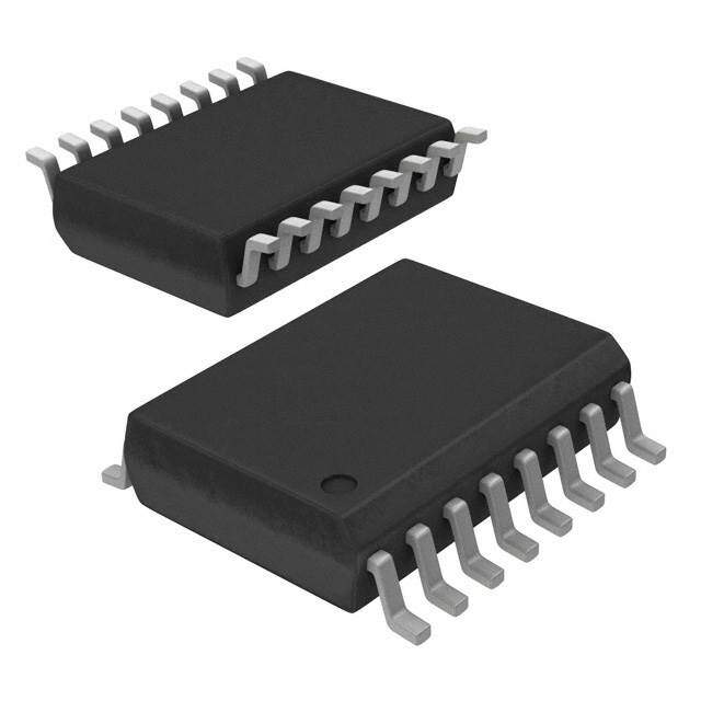
| 产品图片 |
|
| rohs | 符合RoHS无铅 / 符合限制有害物质指令(RoHS)规范要求 |
| 产品系列 | 有源滤波器,Texas Instruments UAF42AU- |
| 数据手册 | |
| 产品型号 | UAF42AU |
| 产品目录页面 | |
| 产品种类 | 有源滤波器 |
| 供应商器件封装 | 16-SOIC |
| 包装 | 管件 |
| 单位重量 | 420.400 mg |
| 商标 | Texas Instruments |
| 安装类型 | 表面贴装 |
| 安装风格 | SMD/SMT |
| 封装 | Tube |
| 封装/外壳 | 16-SOIC(0.295",7.50mm 宽) |
| 封装/箱体 | SOIC-16 |
| 工作电源电压 | 15 V |
| 工厂包装数量 | 40 |
| 截止频率 | 100 kHz |
| 最大工作温度 | + 85 C |
| 最小工作温度 | - 25 C |
| 标准包装 | 40 |
| 滤波器数 | 3 |
| 滤波器类型 | 通用连续计时 |
| 滤波器阶数 | * |
| 电压-电源 | ±6 V ~ 18 V |
| 电源电压-最大 | 18 V |
| 电源电压-最小 | 6 V |
| 系列 | UAF42 |
| 通道数量 | 4 Channel |
| 频率-截止或中心 | 100kHz |

.jpg)


- 商务部:美国ITC正式对集成电路等产品启动337调查
- 曝三星4nm工艺存在良率问题 高通将骁龙8 Gen1或转产台积电
- 太阳诱电将投资9.5亿元在常州建新厂生产MLCC 预计2023年完工
- 英特尔发布欧洲新工厂建设计划 深化IDM 2.0 战略
- 台积电先进制程称霸业界 有大客户加持明年业绩稳了
- 达到5530亿美元!SIA预计今年全球半导体销售额将创下新高
- 英特尔拟将自动驾驶子公司Mobileye上市 估值或超500亿美元
- 三星加码芯片和SET,合并消费电子和移动部门,撤换高东真等 CEO
- 三星电子宣布重大人事变动 还合并消费电子和移动部门
- 海关总署:前11个月进口集成电路产品价值2.52万亿元 增长14.8%


PDF Datasheet 数据手册内容提取
UAF42 UAF42 UAF42 www.ti.com SBFS002B–JULY1992–REVISEDOCTOBER2010 UNIVERSAL ACTIVE FILTER CheckforSamples:UAF42 FEATURES DESCRIPTION 1 • VERSATILE: The UAF42 is a universal active filter that can be 2 – Low-Pass,High-Pass configured for a wide range of low-pass, high-pass, and band-pass filters. It uses a classic state-variable – Band-Pass,Band-Reject analogarchitecturewithaninvertingamplifierandtwo • SIMPLEDESIGNPROCEDURE integrators. The integrators include on-chip 1000pF • ACCURATEFREQUENCYANDQ: capacitors trimmed to 0.5%. This architecture solves one of the most difficult problems of active filter – IncludesOn-Chip1000pF ±0.5%Capacitors design—obtainingtighttolerance,low-losscapacitors. APPLICATIONS A DOS-compatible filter design program allows easy • TESTEQUIPMENT implementation of many filter types, such as Butterworth, Bessel, and Chebyshev. A fourth, • COMMUNICATIONSEQUIPMENT uncommitted FET-input op amp (identical to the other • MEDICALINSTRUMENTATION three) can be used to form additional stages, or for • DATAACQUISITIONSYSTEMS special filters such as band-reject and Inverse • MONOLITHICREPLACEMENTFORUAF41 Chebyshev. The classical topology of the UAF42 forms a time-continuous filter, free from the anomalies and switching noise associated with switched-capacitor filtertypes. The UAF42 is available in 14-pin plastic DIP and SOIC-16 surface-mount packages, specified for the –25°Cto+85°Ctemperaturerange. blank blank blank blank High-Pass Band-Pass Low-Pass Out Out Out R R 1000pF(1) 1000pF(1) V+ In 1 In 2 R R V- In 3 R = 50kW±0.5% GND NOTE:(1)±0.5%. 1 Pleasebeawarethatanimportantnoticeconcerningavailability,standardwarranty,anduseincriticalapplicationsofTexas Instrumentssemiconductorproductsanddisclaimerstheretoappearsattheendofthisdatasheet. Alltrademarksarethepropertyoftheirrespectiveowners. 2 PRODUCTIONDATAinformationiscurrentasofpublicationdate. Copyright©1992–2010,TexasInstrumentsIncorporated Products conform to specifications per the terms of the Texas Instruments standard warranty. Production processing does not necessarilyincludetestingofallparameters.
UAF42 SBFS002B–JULY1992–REVISEDOCTOBER2010 www.ti.com This integrated circuit can be damaged by ESD. Texas Instruments recommends that all integrated circuits be handled with appropriateprecautions.Failuretoobserveproperhandlingandinstallationprocedurescancausedamage. ESDdamagecanrangefromsubtleperformancedegradationtocompletedevicefailure.Precisionintegratedcircuitsmaybemore susceptibletodamagebecauseverysmallparametricchangescouldcausethedevicenottomeetitspublishedspecifications. ABSOLUTE MAXIMUM RATINGS(1) Overoperatingfree-airtemperaturerangeunlessotherwisenoted. UAF42 UNIT PowerSupplyVoltage ±18 V InputVoltage ±V ±0.7 V S OutputShort-Circuit Continuous OperatingTemperature –40to+85 °C StorageTemperature –40to+125 °C JunctionTemperature +125 °C (1) Stressesabovetheseratingsmaycausepermanentdamage.Exposuretoabsolutemaximumconditionsforextendedperiodmay degradedevicereliability.Thesearestressratingsonly,andfunctionaloperationofthedeviceattheseoranyotherconditionsbeyond thosespecifiedisnotsupported. ORDERINGINFORMATION(1) PRODUCT PACKAGE-LEAD PACKAGEDESIGNATOR PACKAGEMARKING UAF42AP PDIP-14 N UAF42AP UAF42APG4 UAF42AU SOIC-16 DW UAF42AU UAF42AUE4 (1) ForthemostcurrentpackageandorderinginformationseethePackageOptionAddendumattheendofthisdocument,orseetheTI websiteatwww.ti.com. PIN CONFIGURATIONS PPACKAGE UPACKAGE PDIP-14 SOIC-16 (TOPVIEW) (TOPVIEW) Low-Pass V 1 14 Frequency Adj O 2 Low-Pass V 1 16 Frequency Adj O 2 VIN3 2 13 High-Pass VO NC(1) 2 15 NC(1) V 3 12 V IN2 IN1 V 3 14 High-Pass V IN3 O Auxiliary Op Amp, +In 4 11 Ground V 4 13 V IN2 IN1 Auxiliary Op Amp,-In 5 10 V+ Auxiliary Op Amp, +In 5 12 Ground Auxiliary Op Amp, VO 6 9 V- Auxiliary Op Amp,-In 6 11 V+ Bandpass VO 7 8 Frequency Adj1 Auxiliary Op Amp, V 7 10 V- O Bandpass V 8 9 Frequency Adj O 1 NOTE:(1)NC=noconnection.Forbest performanceconnectallNCpinstoground tominimizeinter-leadcapacitance. 2 SubmitDocumentationFeedback Copyright©1992–2010,TexasInstrumentsIncorporated ProductFolderLink(s):UAF42
UAF42 www.ti.com SBFS002B–JULY1992–REVISEDOCTOBER2010 ELECTRICAL CHARACTERISTICS AtT =+25°C,andV =±15V,unlessotherwisenoted. A S UAF42AP,AU PARAMETER CONDITIONS MIN TYP MAX UNIT FILTERPERFORMANCE FrequencyRange,fn 0to100 kHz FrequencyAccuracy f=1kHz 1 % vsTemperature 0.01 %/°C MaximumQ 400 — Maximum(Q•Frequency)Product 500 kHz QvsTemperature (fO•Q)<104 0.01 %/°C (fO•Q)<105 0.025 %/°C QRepeatability (fO•Q)<105 2 % OffsetVoltage,Low-PassOutput ±5 mV ResistorAccuracy 0.5 1 % OFFSETVOLTAGE(1) InputOffsetVoltage ±0.5 ±5 mV vsTemperature ±3 mV/°C vsPowerSupply VS=±6Vto±18V 80 96 dB INPUTBIASCURRENT(1) InputBiasCurrent VCM=0V 10 50 pA InputOffsetCurrent VCM=0V 5 pA NOISE InputVoltageNoise NoiseDensity:f=10Hz 25 nV/√Hz NoiseDensity:f=10kHz 10 nV/√Hz VoltageNoise:BW=0.1Hzto10Hz 2 mVPP InputBiasCurrentNoise NoiseDensity:f=10kHz 2 fA/√Hz INPUTVOLTAGERANGE(1) Common-ModeInputRange ±11.5 V Common-ModeRejection VCM=±10V 80 96 dB INPUTIMPEDANCE(1) Differential 1013||2 Ω||pF Common-Mode 1013||6 Ω||pF OPEN-LOOPGAIN(1) Open-LoopVoltageGain VO=±10V,RL=2kΩ 90 126 dB FREQUENCYRESPONSE SlewRate 10 V/ms Gain-BandwidthProduct G=+1 4 MHz TotalHarmonicDistortion G=+1,f=1kHz 0.1 % OUTPUT(1) VoltageOutput RL=2kΩ ±11 ±11.5 V ShortCircuitCurrent ±25 mA (1) Specificationsapplytouncommittedopamp,A .ThethreeopampsformingthefilterareidenticaltoA butaretestedasacomplete 4 4 filter. Copyright©1992–2010,TexasInstrumentsIncorporated SubmitDocumentationFeedback 3 ProductFolderLink(s):UAF42
UAF42 SBFS002B–JULY1992–REVISEDOCTOBER2010 www.ti.com ELECTRICAL CHARACTERISTICS (continued) AtT =+25°C,andV =±15V,unlessotherwisenoted. A S UAF42AP,AU PARAMETER CONDITIONS MIN TYP MAX UNIT POWERSUPPLY SpecifiedOperatingVoltage ±15 V OperatingVoltageRange ±6 ±18 V Current ±6 ±7 mA TEMPERATURERANGE Specified –25 +85 °C Operating –25 +85 °C Storage –40 +125 °C ThermalResistance,qJA 100 °C/W 4 SubmitDocumentationFeedback Copyright©1992–2010,TexasInstrumentsIncorporated ProductFolderLink(s):UAF42
UAF42 www.ti.com SBFS002B–JULY1992–REVISEDOCTOBER2010 APPLICATION INFORMATION The UAF42 is a monolithic implementation of the The basic building element of the most proven state-variable analog filter topology. This commonly-used filter types is the second-order device is pin-compatible with the popular UAF41 section. This section provides a complex-conjugate analogfilter,anditprovidesseveralimprovements. pair of poles. The natural frequency, w , and Q of the n pole pair determine the characteristic response of the The slew rate of the UAF42 has been increased to section. The low-pass transfer function is shown in 10V/ms, versus 1.6V/ms for the UAF41. Equation1: Frequency • Q product of the UAF42 has been w improved, and the useful natural frequency extended V (s) A 2 O = LP n w w by a factor of four to 100kHz. FET input op amps on V(s) s2+ s /Q + 2 I n n (1) the UAF42 provide very low input bias current. The monolithic construction of the UAF42 provides lower The high-pass transfer function is given by costandimprovedreliability. Equation2: V (s) A s2 DESIGN PROGRAM HP = wHP w V(s) s2+ s /Q + 2 I n n (2) Application report SBFA002 (available for download at www.ti.com) and a computer-aided design program The band-pass transfer function is calculated using also available from Texas Instruments, make it easy Equation3: w to design and implement many kinds of active filters. V (s) A ( /Q) s The DOS-compatible program guides you through the BP = BPw n w V(s) s2+ s /Q + 2 design process and automatically calculates I n n (3) componentvalues. A band-reject response is obtained by summing the Low-pass, high-pass, band-pass and band-reject low-pass and high-pass outputs, yielding the transfer (notch)filterscanbedesigned.Theprogramsupports functionshowninEquation4: the three most commonly-used all-pole filter types: V (s) A (s2+w 2) Butterworth, Chebyshev and Bessel. The less-familiar BR = BRw nw V(s) s2+ s /Q + 2 inverse Chebyshev is also supported, providing a I n n (4) smooth passband response with ripple in the stop The most common filter types are formed with one or band. more cascaded second-order sections. Each section With each data entry, the program automatically is designed for w and Q according to the filter type n calculates and displays filter performance. This (Butterworth, Bessel, Chebyshev, etc.) and cutoff feature allows a spreadsheet-like what-if design frequency. While tabulated data can be found in approach.Forexample,ausercanquicklydetermine, virtually any filter design text, the design program by trial and error, how many poles are required for a eliminatesthistediousprocedure. desired attenuation in the stopband. Gain/phase plots Second-order sections may be noninverting maybeviewedforanyresponsetype. (Figure 1) or inverting (Figure 2). Design equations for these two basic configurations are shown for reference. The design program solves these equations, providing complete results, including componentvalues. Copyright©1992–2010,TexasInstrumentsIncorporated SubmitDocumentationFeedback 5 ProductFolderLink(s):UAF42
UAF42 SBFS002B–JULY1992–REVISEDOCTOBER2010 www.ti.com HP Out BP Out LP Out R R F1 F2 12 13 8 7 14 1 R 1 50kW R 2 50kW C1 C2 2 1000pF 1000pF 50kW R A A A G 1 2 3 V 3 IN R 4 50kW R UAF42 Q 11 Note: If R = 50kW, the external gain-setting G resistor can be eliminated by connecting VINto pin 2. Pin numbers are for DIP package. SOIC-16 pinout is different. Design Equations R 1 1 + R R 1. w2= 2 4. A = 2 n R R R C C LP 1 F1 F2 1 2 1 1 1 R + + G R R R G Q 4 R (R +R ) 4 G Q 1/2 2. Q= 1 + 1 +RGRRR12Q RR21RRFF12CC12 5. AHP= RR12 ALP= 11 + RR112 1 R + + G R R R G Q 4 1/2 R R R C 1 1 F1 1 3. QA = QA = A LP HP R BP R R C R 2 2 F2 2 4 6. A = BP R G Figure1. NoninvertingPole-Pair 6 SubmitDocumentationFeedback Copyright©1992–2010,TexasInstrumentsIncorporated ProductFolderLink(s):UAF42
UAF42 www.ti.com SBFS002B–JULY1992–REVISEDOCTOBER2010 HP Out BP Out LP Out R R R G F1 F2 V IN 12 13 8 7 14 1 R 1 50kW R 2 50kW C1 C2 2 1000pF 1000pF 50kW A A A 1 2 3 3 R 4 50kW R Q 11 Note: If R = 50kW, the external Q-setting resistor Q can be eliminated by connecting pin 2 to ground. Pin numbers are for DIP package. SOIC-16 pinout is different. Design Equations R R 1. w2= 2 4. A = 1 n R1RF1RF2C1C2 LP RG 1/2 R4 1 RF1C1 R2 R2 2. Q=1 + 5. A = A = R R R R C HP R LP R Q 1 1 1 1 2 F2 2 1 G + + R R R 1 2 G 1/2 R1 R1RF1C1 R4 1 3. QA = QA = A 6. A = 1 + LP HP R BP R R C BP R 2 2 F2 2 Q 1 1 1 R + + G R R R 1 2 G Figure2. InvertingPole-Pair Copyright©1992–2010,TexasInstrumentsIncorporated SubmitDocumentationFeedback 7 ProductFolderLink(s):UAF42
UAF42 SBFS002B–JULY1992–REVISEDOCTOBER2010 www.ti.com REVISION HISTORY NOTE:Pagenumbersforpreviousrevisionsmaydifferfrompagenumbersinthecurrentversion. ChangesfromRevisionA(November,2007)toRevisionB Page • CorrectedpackagemarkinginformationshowninOrderingInformationtable .................................................................... 2 8 SubmitDocumentationFeedback Copyright©1992–2010,TexasInstrumentsIncorporated ProductFolderLink(s):UAF42
PACKAGE OPTION ADDENDUM www.ti.com 11-Apr-2013 PACKAGING INFORMATION Orderable Device Status Package Type Package Pins Package Eco Plan Lead/Ball Finish MSL Peak Temp Op Temp (°C) Top-Side Markings Samples (1) Drawing Qty (2) (3) (4) UAF42AP ACTIVE PDIP N 14 25 Green (RoHS CU NIPDAU N / A for Pkg Type UAF42AP & no Sb/Br) UAF42AP-1 OBSOLETE PDIP N 14 TBD Call TI Call TI UAF42APG4 ACTIVE PDIP N 14 25 Green (RoHS CU NIPDAU N / A for Pkg Type UAF42AP & no Sb/Br) UAF42AU ACTIVE SOIC DW 16 40 Green (RoHS CU NIPDAU Level-3-260C-168 HR -25 to 85 UAF42AU & no Sb/Br) UAF42AU-1 OBSOLETE SOIC DW 16 TBD Call TI Call TI UAF42AUE4 ACTIVE SOIC DW 16 40 Green (RoHS CU NIPDAU Level-3-260C-168 HR -25 to 85 UAF42AU & no Sb/Br) (1) The marketing status values are defined as follows: ACTIVE: Product device recommended for new designs. LIFEBUY: TI has announced that the device will be discontinued, and a lifetime-buy period is in effect. NRND: Not recommended for new designs. Device is in production to support existing customers, but TI does not recommend using this part in a new design. PREVIEW: Device has been announced but is not in production. Samples may or may not be available. OBSOLETE: TI has discontinued the production of the device. (2) Eco Plan - The planned eco-friendly classification: Pb-Free (RoHS), Pb-Free (RoHS Exempt), or Green (RoHS & no Sb/Br) - please check http://www.ti.com/productcontent for the latest availability information and additional product content details. TBD: The Pb-Free/Green conversion plan has not been defined. Pb-Free (RoHS): TI's terms "Lead-Free" or "Pb-Free" mean semiconductor products that are compatible with the current RoHS requirements for all 6 substances, including the requirement that lead not exceed 0.1% by weight in homogeneous materials. Where designed to be soldered at high temperatures, TI Pb-Free products are suitable for use in specified lead-free processes. Pb-Free (RoHS Exempt): This component has a RoHS exemption for either 1) lead-based flip-chip solder bumps used between the die and package, or 2) lead-based die adhesive used between the die and leadframe. The component is otherwise considered Pb-Free (RoHS compatible) as defined above. Green (RoHS & no Sb/Br): TI defines "Green" to mean Pb-Free (RoHS compatible), and free of Bromine (Br) and Antimony (Sb) based flame retardants (Br or Sb do not exceed 0.1% by weight in homogeneous material) (3) MSL, Peak Temp. -- The Moisture Sensitivity Level rating according to the JEDEC industry standard classifications, and peak solder temperature. (4) Multiple Top-Side Markings will be inside parentheses. Only one Top-Side Marking contained in parentheses and separated by a "~" will appear on a device. If a line is indented then it is a continuation of the previous line and the two combined represent the entire Top-Side Marking for that device. Important Information and Disclaimer:The information provided on this page represents TI's knowledge and belief as of the date that it is provided. TI bases its knowledge and belief on information provided by third parties, and makes no representation or warranty as to the accuracy of such information. Efforts are underway to better integrate information from third parties. TI has taken and Addendum-Page 1
PACKAGE OPTION ADDENDUM www.ti.com 11-Apr-2013 continues to take reasonable steps to provide representative and accurate information but may not have conducted destructive testing or chemical analysis on incoming materials and chemicals. TI and TI suppliers consider certain information to be proprietary, and thus CAS numbers and other limited information may not be available for release. In no event shall TI's liability arising out of such information exceed the total purchase price of the TI part(s) at issue in this document sold by TI to Customer on an annual basis. Addendum-Page 2
None
None
None
IMPORTANTNOTICE TexasInstrumentsIncorporatedanditssubsidiaries(TI)reservetherighttomakecorrections,enhancements,improvementsandother changestoitssemiconductorproductsandservicesperJESD46,latestissue,andtodiscontinueanyproductorserviceperJESD48,latest issue.Buyersshouldobtainthelatestrelevantinformationbeforeplacingordersandshouldverifythatsuchinformationiscurrentand complete.Allsemiconductorproducts(alsoreferredtohereinas“components”)aresoldsubjecttoTI’stermsandconditionsofsale suppliedatthetimeoforderacknowledgment. TIwarrantsperformanceofitscomponentstothespecificationsapplicableatthetimeofsale,inaccordancewiththewarrantyinTI’sterms andconditionsofsaleofsemiconductorproducts.TestingandotherqualitycontroltechniquesareusedtotheextentTIdeemsnecessary tosupportthiswarranty.Exceptwheremandatedbyapplicablelaw,testingofallparametersofeachcomponentisnotnecessarily performed. TIassumesnoliabilityforapplicationsassistanceorthedesignofBuyers’products.Buyersareresponsiblefortheirproductsand applicationsusingTIcomponents.TominimizetherisksassociatedwithBuyers’productsandapplications,Buyersshouldprovide adequatedesignandoperatingsafeguards. TIdoesnotwarrantorrepresentthatanylicense,eitherexpressorimplied,isgrantedunderanypatentright,copyright,maskworkright,or otherintellectualpropertyrightrelatingtoanycombination,machine,orprocessinwhichTIcomponentsorservicesareused.Information publishedbyTIregardingthird-partyproductsorservicesdoesnotconstitutealicensetousesuchproductsorservicesorawarrantyor endorsementthereof.Useofsuchinformationmayrequirealicensefromathirdpartyunderthepatentsorotherintellectualpropertyofthe thirdparty,oralicensefromTIunderthepatentsorotherintellectualpropertyofTI. ReproductionofsignificantportionsofTIinformationinTIdatabooksordatasheetsispermissibleonlyifreproductioniswithoutalteration andisaccompaniedbyallassociatedwarranties,conditions,limitations,andnotices.TIisnotresponsibleorliableforsuchaltered documentation.Informationofthirdpartiesmaybesubjecttoadditionalrestrictions. ResaleofTIcomponentsorserviceswithstatementsdifferentfromorbeyondtheparametersstatedbyTIforthatcomponentorservice voidsallexpressandanyimpliedwarrantiesfortheassociatedTIcomponentorserviceandisanunfairanddeceptivebusinesspractice. TIisnotresponsibleorliableforanysuchstatements. Buyeracknowledgesandagreesthatitissolelyresponsibleforcompliancewithalllegal,regulatoryandsafety-relatedrequirements concerningitsproducts,andanyuseofTIcomponentsinitsapplications,notwithstandinganyapplications-relatedinformationorsupport thatmaybeprovidedbyTI.Buyerrepresentsandagreesthatithasallthenecessaryexpertisetocreateandimplementsafeguardswhich anticipatedangerousconsequencesoffailures,monitorfailuresandtheirconsequences,lessenthelikelihoodoffailuresthatmightcause harmandtakeappropriateremedialactions.BuyerwillfullyindemnifyTIanditsrepresentativesagainstanydamagesarisingoutoftheuse ofanyTIcomponentsinsafety-criticalapplications. Insomecases,TIcomponentsmaybepromotedspecificallytofacilitatesafety-relatedapplications.Withsuchcomponents,TI’sgoalisto helpenablecustomerstodesignandcreatetheirownend-productsolutionsthatmeetapplicablefunctionalsafetystandardsand requirements.Nonetheless,suchcomponentsaresubjecttotheseterms. NoTIcomponentsareauthorizedforuseinFDAClassIII(orsimilarlife-criticalmedicalequipment)unlessauthorizedofficersoftheparties haveexecutedaspecialagreementspecificallygoverningsuchuse. OnlythoseTIcomponentswhichTIhasspecificallydesignatedasmilitarygradeor“enhancedplastic”aredesignedandintendedforusein military/aerospaceapplicationsorenvironments.BuyeracknowledgesandagreesthatanymilitaryoraerospaceuseofTIcomponents whichhavenotbeensodesignatedissolelyattheBuyer'srisk,andthatBuyerissolelyresponsibleforcompliancewithalllegaland regulatoryrequirementsinconnectionwithsuchuse. TIhasspecificallydesignatedcertaincomponentsasmeetingISO/TS16949requirements,mainlyforautomotiveuse.Inanycaseofuseof non-designatedproducts,TIwillnotberesponsibleforanyfailuretomeetISO/TS16949. Products Applications Audio www.ti.com/audio AutomotiveandTransportation www.ti.com/automotive Amplifiers amplifier.ti.com CommunicationsandTelecom www.ti.com/communications DataConverters dataconverter.ti.com ComputersandPeripherals www.ti.com/computers DLP®Products www.dlp.com ConsumerElectronics www.ti.com/consumer-apps DSP dsp.ti.com EnergyandLighting www.ti.com/energy ClocksandTimers www.ti.com/clocks Industrial www.ti.com/industrial Interface interface.ti.com Medical www.ti.com/medical Logic logic.ti.com Security www.ti.com/security PowerMgmt power.ti.com Space,AvionicsandDefense www.ti.com/space-avionics-defense Microcontrollers microcontroller.ti.com VideoandImaging www.ti.com/video RFID www.ti-rfid.com OMAPApplicationsProcessors www.ti.com/omap TIE2ECommunity e2e.ti.com WirelessConnectivity www.ti.com/wirelessconnectivity MailingAddress:TexasInstruments,PostOfficeBox655303,Dallas,Texas75265 Copyright©2015,TexasInstrumentsIncorporated