 Datasheet下载
- 型号: TZY2K450A001R00
- 制造商: Murata
- 库位|库存: xxxx|xxxx
- 要求:
| 数量阶梯 | 香港交货 | 国内含税 |
| +xxxx | $xxxx | ¥xxxx |
查看当月历史价格
查看今年历史价格
TZY2K450A001R00产品简介:
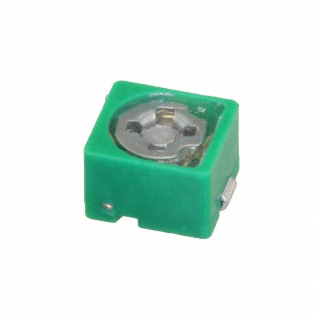
ICGOO电子元器件商城为您提供TZY2K450A001R00由Murata设计生产,在icgoo商城现货销售,并且可以通过原厂、代理商等渠道进行代购。 TZY2K450A001R00价格参考¥2.38-¥5.43。MurataTZY2K450A001R00封装/规格:微调器,可变电容器, 8 ~ 45pF Trimmer Capacitor 25V Top Surface Mount。您可以下载TZY2K450A001R00参考资料、Datasheet数据手册功能说明书,资料中有TZY2K450A001R00 详细功能的应用电路图电压和使用方法及教程。
Murata Electronics North America 生产的 TZY2K450A001R00 是一款微调器(可变电容器),其应用场景广泛,尤其适用于需要精确调节电路参数的场合。以下是该型号的主要应用场景:

 1. 无线通信设备
TZY2K450A00 常用于无线通信设备中,如无线电收发器、对讲机等。在这些设备中,电容器用于调整频率响应和滤波特性,确保信号传输的稳定性和准确性。特别是在射频(RF)电路中,微调电容器可以帮助校准谐振频率,减少干扰并提高通信质量。

 2. 音频设备
在音频设备中,TZY2K450A00 可用于调节音调、均衡器和其他音频处理电路。通过微调电容器,可以实现对音频信号的精细控制,优化音质表现,尤其是在高端音响设备和专业音频系统中,微调器的作用尤为关键。

 3. 医疗设备
在一些医疗设备中,如心电图机、超声波设备等,TZY2K450A00 可用于调节信号处理电路中的滤波器和放大器。这些设备对信号的精度要求极高,微调电容器能够帮助确保测量结果的准确性,避免误诊或错误的医疗判断。

 4. 工业自动化
在工业自动化控制系统中,TZY2K450A00 可用于调节传感器、执行器和其他电子元件的性能。例如,在精密制造过程中,微调电容器可以用于调节反馈回路,确保系统的稳定性和响应速度,从而提高生产效率和产品质量。

 5. 测试与测量仪器
测试与测量仪器,如示波器、频谱分析仪等,通常需要高精度的电容器来调节电路参数。TZY2K450A00 在这些设备中可以用于校准频率响应、带宽和其他关键参数,确保测量结果的准确性和可靠性。

 6. 消费电子产品
在一些高端消费电子产品中,如智能手机、平板电脑等,TZY2K450A00 可用于调节天线匹配电路,确保无线信号的最佳传输效果。此外,它还可以用于其他需要微调功能的电路模块,如蓝牙模块、Wi-Fi模块等。

总之,TZY2K450A00 微调器凭借其高精度和稳定性,广泛应用于各种需要精细调节电容值的场景,特别是在对信号质量和稳定性要求较高的领域。
| 参数 | 数值 |
| 产品目录 | |
| 描述 | CAP TRIMMER 8-45PF 25V SMD整流器/与可变电容器 8.0 - 45pF 25V |
| 产品分类 | |
| 品牌 | Murata Electronics North America |
| 产品手册 | http://search.murata.co.jp/Ceramy/CatalogAction.do?sHinnm=? &sNHinnm=TZY2K450A001R00&sNhin_key=TZY2K450A001R00&sLang=en&sParam=TZY2K |
| 产品图片 |
|
| rohs | 符合RoHS无铅 / 符合限制有害物质指令(RoHS)规范要求 |
| 产品系列 | 整流器/与可变电容器,Murata Electronics TZY2K450A001R00TZY2 |
| 数据手册 | |
| 产品型号 | TZY2K450A001R00 |
| 产品 | Trimmer Capacitors - Ceramic Dielectric |
| 产品目录绘图 |
|
| 产品目录页面 | |
| 产品种类 | 整流器/与可变电容器 |
| 其它名称 | 490-2002-1 |
| 包装 | 剪切带 (CT) |
| 商标 | Murata Electronics |
| 外壳宽度 | 0.098 in |
| 外壳长度 | 0.126 in |
| 外壳高度 | 0.049 in |
| 大小/尺寸 | 矩形 - 0.126" 长 x 0.098" 宽(3.20mm x 2.50mm) |
| 安装类型 | 表面贴装 |
| 容差 | 0.1 % |
| 封装 | Reel |
| 工作温度范围 | - 25 C to + 85 C |
| 工厂包装数量 | 2000 |
| 标准包装 | 1 |
| 温度系数/代码 | N100 +/- 500 PPM / C |
| 特性 | 通用 |
| 电压-额定 | 25V |
| 电压额定值 | 25 V |
| 电容范围 | 8 ~ 45pF |
| 端接类型 | SMD/SMT |
| 类型 | Ceramic Trimmer Capacitor |
| 系列 | TZY2 |
| 调节类型 | 顶部调节 |
| 高度-安装(最大值) | 0.049"(1.25mm) |


- 商务部:美国ITC正式对集成电路等产品启动337调查
- 曝三星4nm工艺存在良率问题 高通将骁龙8 Gen1或转产台积电
- 太阳诱电将投资9.5亿元在常州建新厂生产MLCC 预计2023年完工
- 英特尔发布欧洲新工厂建设计划 深化IDM 2.0 战略
- 台积电先进制程称霸业界 有大客户加持明年业绩稳了
- 达到5530亿美元!SIA预计今年全球半导体销售额将创下新高
- 英特尔拟将自动驾驶子公司Mobileye上市 估值或超500亿美元
- 三星加码芯片和SET,合并消费电子和移动部门,撤换高东真等 CEO
- 三星电子宣布重大人事变动 还合并消费电子和移动部门
- 海关总署:前11个月进口集成电路产品价值2.52万亿元 增长14.8%

PDF Datasheet 数据手册内容提取
T13E.pdf Sep.1,2017 Ceramic Trimmer Capacitors
!Note (cid:129) Please read rating and !CAUTION (for storage, operating, rating, soldering, mounting and handling) in this catalog to prevent smoking and/or burning, etc. T13E.pdf (cid:129) This catalog has only typical specifications. Therefore, please approve our product specifications or transact the approval sheet for product specifications before ordering. Sep.1,2017 EU RoHS Compliant (cid:70)(cid:3)(cid:5)(cid:42)(cid:42)(cid:3)(cid:50)(cid:38)(cid:35)(cid:3)(cid:46)(cid:48)(cid:45)(cid:34)(cid:51)(cid:33)(cid:50)(cid:49)(cid:3)(cid:39)(cid:44)(cid:3)(cid:50)(cid:38)(cid:39)(cid:49)(cid:3)(cid:33)(cid:31)(cid:50)(cid:31)(cid:42)(cid:45)(cid:37)(cid:3)(cid:33)(cid:45)(cid:43)(cid:46)(cid:42)(cid:55)(cid:3) (cid:53)(cid:39)(cid:50)(cid:38)(cid:3)(cid:9)(cid:25)(cid:3)(cid:22)(cid:45)(cid:12)(cid:23)(cid:64) (cid:70)(cid:3)(cid:9)(cid:25)(cid:3)(cid:22)(cid:45)(cid:12)(cid:23)(cid:3)(cid:39)(cid:49)(cid:3)(cid:159)(cid:50)(cid:38)(cid:35)(cid:3)(cid:9)(cid:51)(cid:48)(cid:45)(cid:46)(cid:35)(cid:31)(cid:44)(cid:3)(cid:8)(cid:39)(cid:48)(cid:35)(cid:33)(cid:50)(cid:39)(cid:52)(cid:35)(cid:3) (cid:124)(cid:122)(cid:123)(cid:123)(cid:71)(cid:128)(cid:127)(cid:71)(cid:9)(cid:25)(cid:3)(cid:45)(cid:44)(cid:3)(cid:50)(cid:38)(cid:35)(cid:3)(cid:22)(cid:35)(cid:49)(cid:50)(cid:48)(cid:39)(cid:33)(cid:50)(cid:39)(cid:45)(cid:44)(cid:3)(cid:45)(cid:36)(cid:3)(cid:50)(cid:38)(cid:35)(cid:3) (cid:25)(cid:49)(cid:35)(cid:3)(cid:45)(cid:36)(cid:3)(cid:7)(cid:35)(cid:48)(cid:50)(cid:31)(cid:39)(cid:44)(cid:3)(cid:12)(cid:31)(cid:56)(cid:31)(cid:48)(cid:34)(cid:45)(cid:51)(cid:49)(cid:3)(cid:23)(cid:51)(cid:32)(cid:49)(cid:50)(cid:31)(cid:44)(cid:33)(cid:35)(cid:49)(cid:3)(cid:39)(cid:44)(cid:3) (cid:9)(cid:42)(cid:35)(cid:33)(cid:50)(cid:48)(cid:39)(cid:33)(cid:31)(cid:42)(cid:3)(cid:31)(cid:44)(cid:34)(cid:3)(cid:9)(cid:42)(cid:35)(cid:33)(cid:50)(cid:48)(cid:45)(cid:44)(cid:39)(cid:33)(cid:3)(cid:9)(cid:47)(cid:51)(cid:39)(cid:46)(cid:43)(cid:35)(cid:44)(cid:50)(cid:64)(cid:159)(cid:3) (cid:70)(cid:3)For(cid:3)(cid:43)(cid:45)(cid:48)(cid:35)(cid:3)(cid:34)(cid:35)(cid:50)(cid:31)(cid:39)(cid:42)(cid:49)(cid:65)(cid:3)(cid:46)(cid:42)(cid:35)(cid:31)(cid:49)(cid:35)(cid:3)(cid:48)(cid:35)(cid:36)(cid:35)r(cid:3)(cid:50)o(cid:3)(cid:45)ur(cid:3)(cid:53)(cid:35)(cid:32)(cid:3) (cid:46)(cid:31)(cid:37)(cid:35)(cid:65)(cid:3)(cid:159)(cid:17)(cid:51)(cid:48)(cid:31)(cid:50)(cid:31)(cid:158)(cid:49)(cid:3)(cid:5)(cid:46)(cid:46)(cid:48)(cid:45)(cid:31)(cid:33)(cid:38)(cid:3)(cid:36)(cid:45)(cid:48)(cid:3)(cid:9)(cid:25)(cid:3)(cid:22)(cid:45)(cid:12)(cid:23)(cid:159)(cid:3) (cid:72)(cid:38)(cid:50)(cid:50)(cid:46)(cid:66)(cid:71)(cid:71)(cid:53)(cid:53)(cid:53)(cid:64)(cid:43)(cid:51)(cid:48)(cid:31)(cid:50)(cid:31)(cid:64)(cid:33)(cid:45)(cid:43)(cid:71)(cid:35)(cid:44)- (cid:35)(cid:51)(cid:71)(cid:49)(cid:51)(cid:46)(cid:46)(cid:45)(cid:48)(cid:50)(cid:71)(cid:33)(cid:45)(cid:43)(cid:46)(cid:42)(cid:39)(cid:31)(cid:44)(cid:33)(cid:35)(cid:71)(cid:48)(cid:45)(cid:38)(cid:49)(cid:74)(cid:64)(cid:3)
!Note (cid:129) Please read rating and !CAUTION (for storage, operating, rating, soldering, mounting and handling) in this catalog to prevent smoking and/or burning, etc. T13E.pdf (cid:129) This catalog has only typical specifications. Therefore, please approve our product specifications or transact the approval sheet for product specifications before ordering. Sep.1,2017 Contents Product specifications are as of September 2017. Bluetoothr is a registered trademark or trademark of Bluetooth SIG, Inc. in the United States and other countries. Part Numbering p2 Selection Guide of Ceramic Trimmer Capacitors p3 1 TZR1 Series p4 2 TZY2 Series p8 3 TZC3 Series p13 4 TZW4 Series p18 5 TZB4 Series p21 Packaging p26 Recommended Adjustment Tools p28 Qualified Standards p29 Please check the MURATA website (http://www.murata.com/) if you cannot find a part number in this catalog.
!Note (cid:129) Please read rating and !CAUTION (for storage, operating, rating, soldering, mounting and handling) in this catalog to prevent smoking and/or burning, etc. T13E.pdf (cid:129) This catalog has only typical specifications. Therefore, please approve our product specifications or transact the approval sheet for product specifications before ordering. Sep.1,2017 o Part Numbering Ceramic Trimmer Capacitors (Part Number) TZ Y2 R 200 A C01 R00 1 2 3 4 5 6 7 1Product ID 5Terminal Shape Product ID Code Terminal Shape TZ Trimmer Capacitors A Top Adjustment: TZR1, TZY2, TZC3, TZW4, TZB4 B Top Adjustment: TZB4 2Series/Terminal Please refer to dimensions for terminal details. Code Series/Terminal B4 4mm Size SMD Type 6Individual Specifications W4 4mm Size SMD Type Code Individual Specifications C3 3mm Size SMD Type 001 TZR1, TZW4 Standard Type Y2 2mm Size SMD Type C01 TZY2 Standard Type R1 1mm Size SMD Type A01 TZC3 Standard Type A10 TZB4 No-cover Film Standard Type 3Temperature Characteristics B10 TZB4 with Cover Film Standard Type Code Temperature Characteristics Z NP0ppm/°C 7Packaging R N750ppm/°C Code Packaging K N1000ppm/°C B00 Bulk P N1200ppm/°C R00 Reel (Taping ø180mm) Please refer to ratings for tolerance of temperature characteristics. R01* Reel (Taping ø330mm) * TZB4 only. 4Maximum Capacitance Expressed by three-digit alphanumerics. The unit is pico-farad (pF). The first and second figures are significant digits, and the third figure expresses the number of zeros that follow the two numbers. If there is a decimal point, it is expressed by the capital letter "R". In this case, all figures are significant digits. 2
!Note (cid:129) Please read rating and !CAUTION (for storage, operating, rating, soldering, mounting and handling) in this catalog to prevent smoking and/or burning, etc. T13E.pdf (cid:129) This catalog has only typical specifications. Therefore, please approve our product specifications or transact the approval sheet for product specifications before ordering. Sep.1,2017 Selection Guide Mounting Method? Surface Mount Reflow Flow Height 0.90mm max. Height 1.7mm max. High Frequency Height 3.2mm max. Power TZB4_AB TZR1 TZC3 4.0(W) x 4.5(L) 1.5(W) x 1.7(L) 3.2(W) x 4.5(L) Height 2.6mm max. (with cover film) Height 1.25mm max. Height 3.2mm max. TZW4 TZB4_BB 4.2(W) x 5.2(L) 4.0(W) x 4.5(L) TZY2 TZB4_AA (with cover film) 2.5(W) x 3.2(L) 4.0(W) x 4.5(L) TZB4_BA 4.0(W) x 4.5(L) All Ceramic Trimmer Capacitor products comply with RoHS and ELV. 3
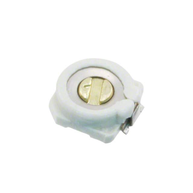
!Note (cid:129) Please read rating and !CAUTION (for storage, operating, rating, soldering, mounting and handling) in this catalog to prevent smoking and/or burning, etc. T13E.pdf (cid:129) This catalog has only typical specifications. Therefore, please approve our product specifications or transact the approval sheet for product specifications before ordering. Sep.1,2017 Ceramic Trimmer Capacitors 1 TZR1 Series 1.7 Features 0.2 (Depth;0.15) 1. Ultra-small and thin with external dimensions of 1.5(W)x1.7(L)x0.85(H)mm 1.5 0.45 (80% less in volume than the current product). 2. Unique construction with no plastic material provides superior soldering heat resistance to 9 max. 0. maintain excellent characteristic performance 0.35 after reflow soldering. 3. Suitable for high frequency circuit due to high self-resonant frequency (6.2GHz of TZR1Z010 at (Tolerance: ±0.1 ) in mm 1.0pF setting). Applications 1. Bluetoothr 2. Crystal oscillators 3. Crystal filters 4. Miniature tuner packs (FM Radio, TV) 5. Remote keyless entry systems C min. (max.) C max. Part Number TC Q Rated Voltage Withstanding Voltage (pF) (pF) TZR1Z010A001 0.55 1.0 +100/-0% NP0±300ppm/°C 200min. at 200MHz, Cmax. 25Vdc 55Vdc TZR1Z1R5A001 0.7 1.5 +100/-0% NP0±300ppm/°C 200min. at 200MHz, Cmax. 25Vdc 55Vdc TZR1Z040A001 1.5 4.0 +100/-0% NP0±500ppm/°C 300min. at 1MHz, Cmax. 25Vdc 55Vdc TZR1R080A001 3.0 8.0 +100/-0% N750±500ppm/°C 300min. at 1MHz, Cmax. 25Vdc 55Vdc Insulation Resistance: 10000M ohm Torque: 0.1 to 1.0mNm Operating Temperature Range: -25 to +85°C Construction Cover Metal Rotor Monolithic Stator 4
!Note (cid:129) Please read rating and !CAUTION (for storage, operating, rating, soldering, mounting and handling) in this catalog to prevent smoking and/or burning, etc. T13E.pdf (cid:129) This catalog has only typical specifications. Therefore, please approve our product specifications or transact the approval sheet for product specifications before ordering. Sep.1,2017 Temperature Characteristics TZR1Z010 TZR1Z1R5 1 Z010 (NP0±300 ppm/°C) Z1R5 (NP0±300 ppm/°C) 8 8 6 6 4 4 2 2 –25 20 85 –25 20 85 Temp. (°C) Temp. (°C) –2 –2 –4 –4 %) %) e ( –6 e ( –6 g g an –8 an –8 h h C C p. –10 p. –10 a a C–12 C–12 TZR1Z040 TZR1R080 Z040 (NP0±500 ppm/°C) R080 (N750±500 ppm/°C) 8 8 6 6 4 4 2 2 –25 20 85 –25 20 85 Temp. (°C) Temp. (°C) –2 –2 –4 –4 %) %) e ( –6 e ( –6 g g an –8 an –8 h h C C p. –10 p. –10 a a C–12 C–12 Frequency Characteristics TZR1Z010 TZR1Z1R5 Z010 Z1R5 10000 10000 1000 1000 100 100 0.55pF set 0.7pF set Q Q 10 10 1.0pF set 1.5pF set 1 1 0 0 0 2 4 6 8 10 0 2 4 6 8 10 Frequency (GHz) Frequency (GHz) TZR1Z040 TZR1R080 Z040 R080 1000 1000 1000 1000 F) F) 100 100 p 100 100 p e ( e ( c c Q an Q an cit cit a a p p 10 10 Ca 10 10 Ca 1 1 500 1000 1500 2000 2500 500 1000 1500 2000 Frequency (MHz) Frequency (MHz) 5
!Note (cid:129) Please read rating and !CAUTION (for storage, operating, rating, soldering, mounting and handling) in this catalog to prevent smoking and/or burning, etc. T13E.pdf (cid:129) This catalog has only typical specifications. Therefore, please approve our product specifications or transact the approval sheet for product specifications before ordering. Sep.1,2017 Land Pattern 1 2.2 1.2 5 0. (Tolerance: ±0.1 ) in mm Temperature Profile oReflow Soldering Profile n1 Soldering profile for Lead-free solder (96.5Sn/3Ag/0.5Cu) n2 Soldering profile for Eutectic solder (63Sn/37Pb) (Limit profile: refer to n1 ) T5 Temperature (°C)T1 TT32 tt32 T4LSitmanitd Parrodfi Plerofile Temperature (°C)T1 TT32 t2 Standard Profile t1 time (s) t1 time (s) Standard Profile Standard Profile Pre-heating Heating Peak Cycle Pre-heating Heating Peak Cycle temperature temperature Temp. (T1) Time (t1) Temp. (T2) Time (t2) (T3) of reflow Temp. (T1) Time (t1) Temp. (T2) Time (t2) (T3) of reflow 150 to 180°C60 to 120sec. 220°C 30 to 60sec. 245±3°C 2 times 150°C 60 to 120sec. 183°C 30sec. 230 +5/-0°C 1 time Limit Profile Pre-heating Heating Peak Cycle temperature Temp. (T1) Time (t1) Temp. (T4) Time (t3) (T5) of reflow 150 to 180°C60 to 120sec. 230°C 30 to 50sec. 260 +5/-0°C 2 times oSoldering Iron Standard Profile Temperature of soldering iron tip Soldering time Soldering iron power output Cycle of soldering iron 350±10°C 3sec. max. 30W max. 1 time Notice (Storage and Operating Conditions) 1. Do not use the trimmer capacitor under atmosphere 6. Do not use the trimmer capacitor under the of RTV silicone rubber (Room Temperature conditions listed below. Vulcanizing Silicone Rubber) except Acetone (1) Corrosive gasses atmosphere liberating silicone sealant. (ex. Chlorine gas, Hydrogen sulfide gas, 2. Before using trimmer capacitors, please store under Ammonia gas, Sulfuric acid gas, Nitric oxide gas, the conditions of -10 to +40°C and 30 to etc.) 85%RH. (2) In liquid (ex. water, oil, medical liquid, 3. Do not store in or near corrosive gasses. organic solvent, etc.) 4. Use within 6 months of delivery. (3) Dusty / dirty atmosphere 5. Do not store under direct sunlight. (4) Direct sunlight (5) Static voltage or electric/magnetic fields (6) Direct sea breeze (7) Other variations of the above 6
!Note (cid:129) Please read rating and !CAUTION (for storage, operating, rating, soldering, mounting and handling) in this catalog to prevent smoking and/or burning, etc. T13E.pdf (cid:129) This catalog has only typical specifications. Therefore, please approve our product specifications or transact the approval sheet for product specifications before ordering. Sep.1,2017 Notice (Soldering and Mounting) 1. Soldering (6) Our recommended chlorine content of solder is 1 (1) TZR1 series can be soldered by reflow soldering as follows. method and soldering iron. Do not use flow (a) Solder paste: 0.2wt% max. soldering method (dipping). (b) String solder: 0.5wt% max. (2) Soldering conditions (7) Do not use water-soluble flux (for water Refer to the temperature profile. cleaning). To prevent the deterioration of If the soldering conditions are not suitable, e.g., trimmer capacitor characteristics, apply flux excessive time and/or excessive temperature, the only to terminals. trimmer capacitor may deviate from the specified 2. Mounting characteristics. (1) Do not apply excessive force (preferably 5.0 N (3) The amount of solder is critical. [Ref: 500gf] max.), when the trimmer capacitor (4) The thickness of solder paste should be printed is mounted on the PCB. from 100 micro m to 150 micro m and the dimension (2) Do not warp and/or bend PCB to protect trimmer of land pattern should be Murata's standard land capacitor from breaking. pattern used at reflow soldering. (3) Use a pick-up nozzle of a suitable dimension. Insufficient amounts of solder can lead to (1.6mm external diameter and 0.8mm bore insufficient soldering strength on PCB. diameter.) Excessive amounts of solder may cause bridging 3. Cleaning between the terminals or contact failure due to This product cannot be cleaned because of open flux wicking up. construction. (5) When using soldering iron, the diameter of the 4. Other string solder shall be less than 0.5mm. The Note the polarity of the trimmer capacitor to string solder shall be applied to the lower minimize influence by stray capacitance. part of the terminal only. Do not apply flux (Refer to the dimensions concerning the polarity.) except to the terminals. Excessive amounts of solder and/or applying solder to the upper part of the terminal may cause fixed metal rotor or contact failure due to flux invasion into the movable part and/or the contact point. The soldering iron should not come in contact with the monolithic stator of the trimmer capacitor. If such contact does occur, the trimmer capacitor may be damaged. Notice (Handling) 1. Use suitable screwdrivers that fit comfortably in 3. Do not apply adhesive, lock paints, or any other driver slot. substances to the trimmer capacitor to secure the *Recommended screwdriver for manual adjustment rotor position. They may cause corrosion or MURATA: KMDR160 electrical contact problems. 2. When adjusting with a screwdriver, do not apply excessive force (preferably 0.5 N [Ref: 50gf] max.) to minimize capacitance drift. Excessive force applied to the screwdriver slot may cause deformation of the products. Notice (Other) Before using trimmer capacitors, please test after assembly in your particular mass production system. 7
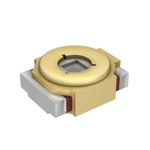
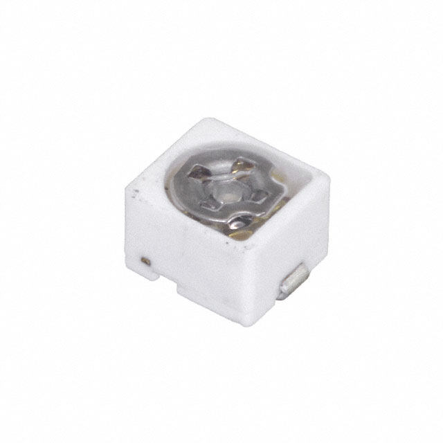
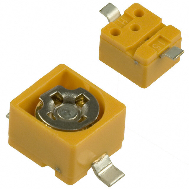
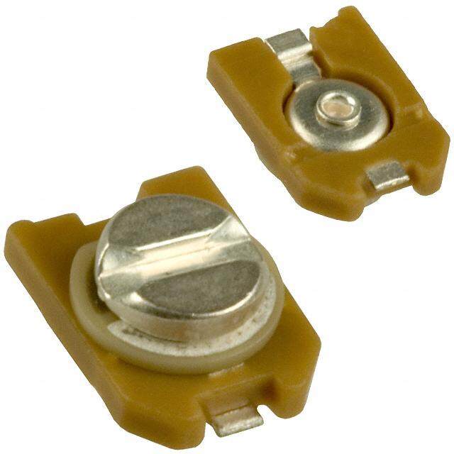
!Note (cid:129) Please read rating and !CAUTION (for storage, operating, rating, soldering, mounting and handling) in this catalog to prevent smoking and/or burning, etc. T13E.pdf (cid:129) This catalog has only typical specifications. Therefore, please approve our product specifications or transact the approval sheet for product specifications before ordering. Sep.1,2017 Ceramic Trimmer Capacitors TZY2 Series 3.2±0.2 Features 0.45 1. Small and thin size with external dimensions 2 2 of 2.5(W)x3.2(L)x1.25max.(H)mm. 2.5±0.0.95 1.0 2. New shape of cover can improve the flux invasion compared with current products. max. 3. Improvement of the adhesion between rotor and 5 2 1. stator leads to superior stability. 0.5 4. Unique construction with no plastic material provides superior soldering heat resistance to 1.4 maintain excellent characteristic performance (Tolerance: ±0.1 ) in mm after reflow soldering. 5. Suitable for high frequency circuit due to high self-resonant frequency (4.8GHz of TZY2Z010 at 1.0pF setting). Applications 1. Crystal oscillators 7. W-LAN 2. Crystal filters 8. Radar detectors 3. Stylus pen 9. Compact radios 4. Hand radios 10. Burglarproof devices 5. Watches 11. Headphone stereos 6. Remote keyless entry systems C min. (max.) C max. Part Number TC Q Rated Voltage Withstanding Voltage (pF) (pF) TZY2Z010AC01 0.6 1.0 +100/-0% NP0±300ppm/°C 200min. at 200MHz, Cmax. 25Vdc 55Vdc TZY2Z2R5AC01 1.0 2.5 +100/-0% NP0±300ppm/°C 200min. at 200MHz, Cmax. 25Vdc 55Vdc TZY2Z030AC01 1.5 3.0 +100/-0% NP0±300ppm/°C 300min. at 1MHz, Cmax. 25Vdc 55Vdc TZY2Z060AC01 2.5 6.0 +100/-0% NP0±300ppm/°C 500min. at 1MHz, Cmax. 25Vdc 55Vdc TZY2Z100AC01 3.0 10.0 +100/-0% NP0±300ppm/°C 500min. at 1MHz, Cmax. 25Vdc 55Vdc TZY2R200AC01 4.5 20.0 +100/-0% N750±500ppm/°C 500min. at 1MHz, Cmax. 25Vdc 55Vdc TZY2R250AC01 5.5 25.0 +100/-0% N750±500ppm/°C 300min. at 1MHz, Cmax. 25Vdc 55Vdc TZY2K450AC01 8.0 45.0 +100/-0% N1000±500ppm/°C 300min. at 1MHz, Cmax. 25Vdc 55Vdc Insulation Resistance: 10000M ohm Torque: 0.7 to 4.9mNm Operating Temperature Range: -25 to +85°C Construction Cover Metal Rotor Monolithic Stator 8
!Note (cid:129) Please read rating and !CAUTION (for storage, operating, rating, soldering, mounting and handling) in this catalog to prevent smoking and/or burning, etc. T13E.pdf (cid:129) This catalog has only typical specifications. Therefore, please approve our product specifications or transact the approval sheet for product specifications before ordering. Sep.1,2017 Temperature Characteristics TZY2Z010 TZY2Z2R5 Z010 (NP0±300 ppm/°C) Z2R5 (NP0±300 ppm/°C) 8 8 6 6 4 4 2 2 –25 20 85 –25 20 85 Temp. (°C) Temp. (°C) –2 –2 2 –4 –4 %) %) e ( –6 e ( –6 g g an –8 an –8 h h C C p. –10 p. –10 a a C–12 C–12 TZY2Z030 TZY2Z060 Z030 (NP0±300 ppm/°C) Z060 (NP0±300 ppm/°C) 8 8 6 6 4 4 2 2 –25 20 85 –25 20 85 Temp. (°C) Temp. (°C) –2 –2 –4 –4 %) %) e ( –6 e ( –6 g g an –8 an –8 h h C C p. –10 p. –10 a a C–12 C–12 TZY2Z100 TZY2R200 Z100 (NP0±300 ppm/°C) R200 (N750±500 ppm/°C) 8 8 6 6 4 4 2 2 –25 20 85 –25 20 85 Temp. (°C) Temp. (°C) –2 –2 –4 –4 %) %) e ( –6 e ( –6 g g an –8 an –8 h h C C p. –10 p. –10 a a C–12 C–12 TZY2R250 TZY2K450 R250 (N750±500 ppm/°C) K450 (N1000±500 ppm/°C) 8 8 6 6 4 4 2 2 –25 20 85 –25 20 85 Temp. (°C) Temp. (°C) –2 –2 –4 –4 %) %) e ( –6 e ( –6 g g an –8 an –8 h h C C p. –10 p. –10 a a C–12 C–12 9
!Note (cid:129) Please read rating and !CAUTION (for storage, operating, rating, soldering, mounting and handling) in this catalog to prevent smoking and/or burning, etc. T13E.pdf (cid:129) This catalog has only typical specifications. Therefore, please approve our product specifications or transact the approval sheet for product specifications before ordering. Sep.1,2017 Frequency Characteristics TZY2Z010 TZY2Z100 Z010 Z100 1000 1000 1000 100 0.5pF set 100 100 ce (pF) 2 Q Q citan a p 10 a C 10 10 1.0pF set 1 1 0 2 4 6 8 200 400 600 800 1000 Frequency (GHz) Frequency (MHz) TZY2R200 TZY2K450 R200 K450 1000 1000 1000 1000 F) F) p 100 100 p 100 100 e ( e ( c c Q an Q an cit cit a a p p Ca 10 10 Ca 10 10 1 1 200 400 600 800 1000 200 400 600 800 Frequency (MHz) Frequency (MHz) Land Pattern 4.0 2.4 2 1. (Tolerance: ±0.1 ) in mm 10
!Note (cid:129) Please read rating and !CAUTION (for storage, operating, rating, soldering, mounting and handling) in this catalog to prevent smoking and/or burning, etc. T13E.pdf (cid:129) This catalog has only typical specifications. Therefore, please approve our product specifications or transact the approval sheet for product specifications before ordering. Sep.1,2017 Temperature Profile oReflow Soldering Profile n1 Soldering profile for Lead-free solder (96.5Sn/3Ag/0.5Cu) n2 Soldering profile for Eutectic solder (63Sn/37Pb) (Limit profile: refer to n1 ) T5 Temperature (°C)T1 TT32 tt32 T4LSitmanitd Parrodfi Plerofile Temperature (°C)T1 TT32 t2 Standard Profile 2 t1 time (s) t1 time (s) Standard Profile Standard Profile Pre-heating Heating Peak Cycle Pre-heating Heating Peak Cycle temperature temperature Temp. (T1) Time (t1) Temp. (T2) Time (t2) (T3) of reflow Temp. (T1) Time (t1) Temp. (T2) Time (t2) (T3) of reflow 150 to 180°C60 to 120sec. 220°C 30 to 60sec. 245±3°C 2 times 150°C 60 to 120sec. 183°C 30sec. 230 +5/-0°C 1 time Limit Profile Pre-heating Heating Peak Cycle temperature Temp. (T1) Time (t1) Temp. (T4) Time (t3) (T5) of reflow 150 to 180°C60 to 120sec. 230°C 30 to 50sec. 260 +5/-0°C 2 times oSoldering Iron Standard Profile Temperature of soldering iron tip Soldering time Soldering iron power output Cycle of soldering iron 350±10°C 3sec. max. 30W max. 1 time Notice (Storage and Operating Conditions) 1. Do not use the trimmer capacitor under atmosphere 6. Do not use the trimmer capacitor under the of RTV silicone rubber (Room Temperature conditions listed below. Vulcanizing Silicone Rubber) except Acetone (1) Corrosive gasses atmosphere liberating silicone sealant. (ex. Chlorine gas, Hydrogen sulfide gas, 2. Before using trimmer capacitors, please store under Ammonia gas, Sulfuric acid gas, Nitric oxide gas, the conditions of -10 to +40°C and 30 to etc.) 85%RH. (2) In liquid (ex. water, oil, medical liquid, 3. Do not store in or near corrosive gasses. organic solvent, etc.) 4. Use within 6 months of delivery. (3) Dusty / dirty atmosphere 5. Do not store under direct sunlight. (4) Direct sunlight (5) Static voltage or electric/magnetic fields (6) Direct sea breeze (7) Other variations of the above 11
!Note (cid:129) Please read rating and !CAUTION (for storage, operating, rating, soldering, mounting and handling) in this catalog to prevent smoking and/or burning, etc. T13E.pdf (cid:129) This catalog has only typical specifications. Therefore, please approve our product specifications or transact the approval sheet for product specifications before ordering. Sep.1,2017 Notice (Soldering and Mounting) 1. Soldering (6) Our recommended chlorine content of solder is (1) TZY2 series can be soldered by reflow soldering as follows. method and soldering iron. Do not use flow (a) Solder paste: 0.2wt% max. soldering method (dipping). (b) String solder: 0.5wt% max. (2) Soldering conditions (7) Do not use water-soluble flux (for water Refer to the temperature profile. cleaning). To prevent the deterioration of If the soldering conditions are not suitable, e.g., trimmer capacitor characteristics, apply flux excessive time and/or excessive temperature, the only to terminals. 2 trimmer capacitor may deviate from the specified 2. Mounting characteristics. (1) Do not apply excessive force (preferably 5.0 N (3) The amount of solder is critical. [Ref: 500gf] max.), when the trimmer capacitor (4) The thickness of solder paste should be printed is mounted on the PCB. from 120 micro m to 170 micro m and the dimension (2) Do not warp and/or bend PCB to protect trimmer of land pattern should be Murata's standard land capacitor from breakage. pattern used at reflow soldering. (3) Use a pick-up nozzle of a suitable dimension. Insufficient amounts of solder can lead to (2.5mm external diameter and 1.2mm bore insufficient soldering strength on PCB. diameter.) Excessive amounts of solder may cause bridging 3. Cleaning between the terminals or contact failure due to This product cannot be cleaned because of open flux wicking up. construction. (5) When using soldering iron, the diameter of the 4. Other string solder shall be less than 0.5mm. The Note the polarity of the trimmer capacitor to string solder shall be applied to the lower minimize influence by stray capacitance. part of the terminal only. Do not apply flux (Refer to the dimensions concerning the polarity.) except to the terminals. Excessive amounts of solder and/or applying solder to the upper part of the terminal may cause fixed metal rotor or contact failure due to flux invasion into the movable part and/or the contact point. The soldering iron should not come in contact with the monolithic stator of the trimmer capacitor. If such contact does occur, the trimmer capacitor may be damaged. Notice (Handling) 1. Use suitable screwdrivers that fit comfortably in 2. When adjusting with a screwdriver, do not apply driver slot. excessive force (preferably 1.0 N [Ref: 100gf] max.) (1) Recommended screwdriver for manual adjustment to minimize capacitance drift. Excessive force applied MURATA: KMDR020 to the screwdriver slot may cause deformation of the (2) Recommended screwdriver bit for automatic products. adjustment 3. Do not apply adhesive, lock paints, or any other MURATA: KMBT020 substances to the trimmer capacitor to secure the rotor position. They may cause corrosion or electrical contact problems. Notice (Other) Before using trimmer capacitor, please test after assembly in your particular mass production system. 12
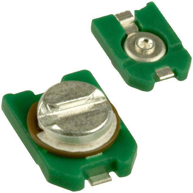
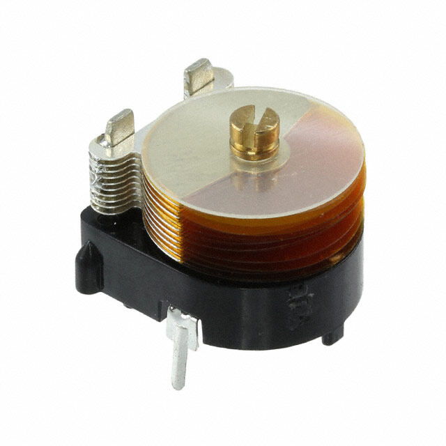
!Note (cid:129) Please read rating and !CAUTION (for storage, operating, rating, soldering, mounting and handling) in this catalog to prevent smoking and/or burning, etc. T13E.pdf (cid:129) This catalog has only typical specifications. Therefore, please approve our product specifications or transact the approval sheet for product specifications before ordering. Sep.1,2017 Ceramic Trimmer Capacitors TZC3 Series 0.5±0.05 Depth 0.4±0.05 Features 1. Small size with external dimension of 3.2 - +2.0 3.2(W)x4.5(L)x1.6(H)mm. 2.0 dia. 2. Can be adjusted with conventional adjustment tools 4.5 having a thickness of 0.5mm. 3. Designed for automatic placement in surface mount 1.6 applications. 4. Heat resistant resin withstands reflow soldering 0.8 0.75 temperatures. 3 (Tolerance: ±0.1 ) 0.6 0.6 in mm Applications 1. Compact radios 2. Stylus pen 3. Portable radio equipment 4. Hybrid ICs 5. Remote keyless entry systems C min. (max.) C max. Part Number TC Q Rated Voltage Withstanding Voltage (pF) (pF) TZC3Z030AA01 1.4 3.0 +50/-0% NP0±300ppm/°C 300min. at 1MHz, Cmax. 100Vdc 220Vdc TZC3Z060AA01 2.0 6.0 +50/-0% NP0±300ppm/°C 500min. at 1MHz, Cmax. 100Vdc 220Vdc TZC3R100AA01 3.0 10.0 +50/-0% N750±300ppm/°C 500min. at 1MHz, Cmax. 100Vdc 220Vdc TZC3P200AA01 5.0 20.0 +50/-0% N1200±500ppm/°C 300min. at 1MHz, Cmax. 100Vdc 220Vdc TZC3P300AA01 6.5 30.0 +50/-0% N1200±500ppm/°C 300min. at 1MHz, Cmax. 100Vdc 220Vdc Insulation Resistance: 10000M ohm Torque: 1.5 to 9.8mNm Operating Temperature Range: -25 to +85°C Construction Center Axis Ceramic Stator Rotor Spring Terminal Stator Electrode Terminal 13
!Note (cid:129) Please read rating and !CAUTION (for storage, operating, rating, soldering, mounting and handling) in this catalog to prevent smoking and/or burning, etc. T13E.pdf (cid:129) This catalog has only typical specifications. Therefore, please approve our product specifications or transact the approval sheet for product specifications before ordering. Sep.1,2017 Temperature Characteristics TZC3Z030 TZC3Z060 Z030 (NP0±300 ppm/°C) Z060 (NP0±300 ppm/°C) 8 8 6 6 4 4 2 2 –25 20 85 –25 20 85 Temp. (°C) Temp. (°C) –2 –2 –4 –4 %) %) e ( –6 e ( –6 g g an –8 an –8 h h C C p. –10 p. –10 a a C–12 C–12 3 TZC3R100 TZC3P200 R100 (N750±300 ppm/°C) P200 (N1200±500 ppm/°C) 8 8 6 6 4 4 2 2 –25 20 85 –25 20 85 Temp. (°C) Temp. (°C) –2 –2 –4 –4 %) %) e ( –6 e ( –6 g g an –8 an –8 h h C C p. –10 p. –10 a a C–12 C–12 TZC3P300 P300 (N1200±500 ppm/°C) 8 6 4 2 –25 20 85 Temp. (°C) –2 –4 %) e ( –6 g an –8 h C p. –10 a C–12 14
!Note (cid:129) Please read rating and !CAUTION (for storage, operating, rating, soldering, mounting and handling) in this catalog to prevent smoking and/or burning, etc. T13E.pdf (cid:129) This catalog has only typical specifications. Therefore, please approve our product specifications or transact the approval sheet for product specifications before ordering. Sep.1,2017 Frequency Characteristics TZC3Z030 TZC3Z060 Z030 Z060 1000 1000 1000 1000 F) F) p p 100 100 e ( 100 100 e ( c c Q an Q an cit cit a a p p a a C C 10 10 10 10 1 1 100 500 1000 1500 2000 100 500 1000 1500 2000 Frequency (MHz) Frequency (MHz) TZC3R100 TZC3P200 3 R100 P200 1000 1000 1000 1000 F) F) p p 100 100 e ( 100 100 e ( c c Q an Q an cit cit a a p p a a C C 10 10 10 10 1 1 200 400 600 800 1000 200 400 600 800 1000 Frequency (MHz) Frequency (MHz) Land Pattern 5.0+-00.5 3.3±0.1 1 0. 0± 1. (Tolerance: ±0.1 ) in mm 15
!Note (cid:129) Please read rating and !CAUTION (for storage, operating, rating, soldering, mounting and handling) in this catalog to prevent smoking and/or burning, etc. T13E.pdf (cid:129) This catalog has only typical specifications. Therefore, please approve our product specifications or transact the approval sheet for product specifications before ordering. Sep.1,2017 Temperature Profile oReflow Soldering Profile n1 Soldering profile for Lead-free solder (96.5Sn/3Ag/0.5Cu) n2 Soldering profile for Eutectic solder (63Sn/37Pb) (Limit profile: refer to n1 ) T5 Temperature (°C)T1 TT32 tt32 T4LSitmanitd Parrodfi Plerofile Temperature (°C)T1 TT32 t2 Standard Profile t1 time (s) t1 time (s) Standard Profile Standard Profile Pre-heating Heating Peak Cycle Pre-heating Heating Peak Cycle temperature temperature Temp. (T1) Time (t1) Temp. (T2) Time (t2) (T3) of reflow Temp. (T1) Time (t1) Temp. (T2) Time (t2) (T3) of reflow 150 to 180°C60 to 120sec. 220°C 30 to 60sec. 245±3°C 2 times 150°C 60 to 120sec. 183°C 30sec. 230 +5/-0°C 1 time 3 Limit Profile Pre-heating Heating Peak Cycle temperature Temp. (T1) Time (t1) Temp. (T4) Time (t3) (T5) of reflow 150 to 180°C60 to 120sec. 230°C 30 to 50sec. 260 +5/-0°C 2 times oSoldering Iron Standard Profile Temperature of soldering iron tip Soldering time Soldering iron power output Cycle of soldering iron 350±10°C 3sec. max. 30W max. 1 time Notice (Storage and Operating Conditions) 1. Do not use the trimmer capacitor under atmosphere 6. Do not use the trimmer capacitor under the of RTV silicone rubber (Room Temperature conditions listed below. Vulcanizing Silicone Rubber) except Acetone (1) Corrosive gasses atmosphere liberating silicone sealant. (ex. Chlorine gas, Hydrogen sulfide gas, 2. Before using trimmer capacitors, please store under Ammonia gas, Sulfuric acid gas, Nitric oxide gas, the conditions of -10 to +40°C and 30 to etc.) 85%RH. (2) In liquid (ex. water, oil, medical liquid, 3. Do not store in or near corrosive gasses. organic solvent, etc.) 4. Use within 6 months of delivery. (3) Dusty / dirty atmosphere 5. Do not store under direct sunlight. (4) Direct sunlight (5) Static voltage or electric/magnetic fields (6) Direct sea breeze (7) Other variations of the above 16
!Note (cid:129) Please read rating and !CAUTION (for storage, operating, rating, soldering, mounting and handling) in this catalog to prevent smoking and/or burning, etc. T13E.pdf (cid:129) This catalog has only typical specifications. Therefore, please approve our product specifications or transact the approval sheet for product specifications before ordering. Sep.1,2017 Notice (Soldering and Mounting) 1. Soldering (6) Our recommended chlorine content of solder is (1) TZC3 series can be soldered by reflow soldering as follows. method and soldering iron. Do not use flow (a) Solder paste: 0.2wt% max. soldering method (dipping). (b) String solder: 0.5wt% max. (2) Soldering conditions (7) Do not use water-soluble flux (for water Refer to the temperature profile. cleaning). To prevent the deterioration of If the soldering conditions are not suitable, e.g., trimmer capacitor characteristics, apply flux excessive time and/or excessive temperature, the only to terminals. trimmer capacitor may deviate from the specified (8) When soldering the TZC3 series, the solder characteristics. should not flow into the staking part of the (3) The amount of solder is critical. substrate. If such flow does occur, driver slot (4) The thickness of solder paste should be printed rotation will be damaged. from 150 micro m to 200 micro m and the dimension 2. Mounting of land pattern should be Murata's standard land (1) Do not apply excessive force (preferably 5.0 N pattern used at reflow soldering. [Ref: 500gf] max.), when the trimmer capacitor 3 Insufficient amounts of solder can lead to is mounted on the PCB. insufficient soldering strength on PCB. (2) Do not warp and/or bend PCB to protect trimmer Excessive amounts of solder may cause bridging capacitor from breakage. between the terminals or contact failure due to (3) Use a pick-up nozzle of a suitable dimension. flux wicking up. (2.5mm external diameter and 1.5mm bore (5) When using soldering iron, the diameter of the diameter.) string solder shall be less than 0.5mm. The 3. Cleaning string solder shall be applied to the lower This product cannot be cleaned because of open part of the terminal only. Do not apply flux construction. except to the terminals. Excessive amounts of 4. Other solder and/or applying solder to the upper part Note the polarity of the trimmer capacitor to of the terminal may cause fixed metal rotor or minimize influence by stray capacitance. contact failure due to flux invasion into the (Refer to the dimensions concerning the polarity.) movable part and/or the contact point. The soldering iron should not come in contact with the stator of the trimmer capacitor. If such contact does occur, the trimmer capacitor may be damaged. Notice (Handling) 1. Use suitable screwdrivers that fit comfortably in 3. Do not apply adhesive, lock paints, or any other driver slot. substances to the trimmer capacitor to secure the Recommended screwdriver for manual adjustment rotor position. They may cause corrosion or Standard type --> MURATA: KMDR080 electrical contact problems. 2. When adjusting with a screwdriver, do not apply excessive force (preferably 1.0 N [Ref: 100gf] max.) to minimize capacitance drift. Excessive force applied to the screwdriver slot may cause deformation of the products. Notice (Other) Before using trimmer capacitors, please test after assembly in your particular mass production system. 17
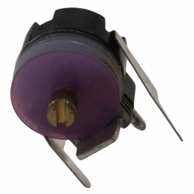
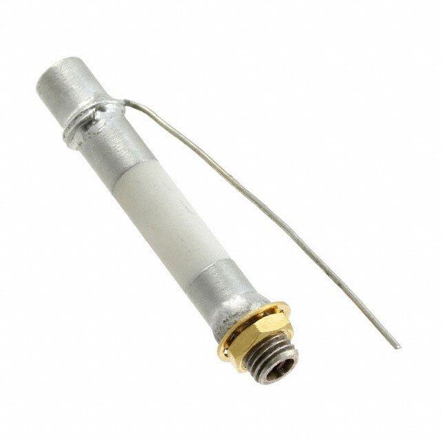
!Note (cid:129) Please read rating and !CAUTION (for storage, operating, rating, soldering, mounting and handling) in this catalog to prevent smoking and/or burning, etc. T13E.pdf (cid:129) This catalog has only typical specifications. Therefore, please approve our product specifications or transact the approval sheet for product specifications before ordering. Sep.1,2017 Ceramic Trimmer Capacitors TZW4 Series 5.2±0.2 1.6 Features 0.4 Depth 1. To meet high power application due to withstanding 0.2 0.6 2± voltage 550Vdc. 4. 2. Extremely high self-resonant frequency. (More than 3GHz at rated C max.) max. 6 2. 3. Typical application: Impedance matching for Cellular 3.0 Base Station. 4. High Q value in more than VHF, UHF and Microwave 2 0. bands. 2.8± (More than 200 in 500MHz, C max.) 2.2 0.3+-00..21 (Tolerancein: ± m0.m1 ) 5. Available for pick and place machine. Possible thinner design due to 2.6mm low profile. 6. Non-electrical contact construction (rotor as middle electrode) provides high reliability. 7. Compact size: 4.2(W)x5.2(L)x2.6max.(H)mm. 4 Applications 1. Transmitting power amplifier for Cellular base station 2. Transmitting amplifier for PHS base station 3. High frequency electric circuit 4. High power radio transmission 5. Transponder amplifier for cable TV C min. (max.) C max. Part Number TC Q Rated Voltage Withstanding Voltage (pF) (pF) TZW4Z010A001 0.4 1.0 +50/-0% NP0±150ppm/°C 200min. at 500MHz, Cmax. 250Vdc 550Vdc TZW4Z1R5A001 0.4 1.5 +100/-0% NP0±150ppm/°C 200min. at 500MHz, Cmax. 250Vdc 550Vdc Insulation Resistance: 10000M ohm Torque: 1.5 to 10.0mNm Operating Temperature Range: -55 to +125°C Construction Metal Rotor Cover Monolithic Stator 18
!Note (cid:129) Please read rating and !CAUTION (for storage, operating, rating, soldering, mounting and handling) in this catalog to prevent smoking and/or burning, etc. T13E.pdf (cid:129) This catalog has only typical specifications. Therefore, please approve our product specifications or transact the approval sheet for product specifications before ordering. Sep.1,2017 Temperature Characteristics TZW4Z010 TZW4Z1R5 Z010 (NP0±150 ppm/°C) Z1R5 (NP0±300 ppm/°C) 8 8 6 6 4 4 2 2 –55 20 125 –55 20 125 Temp. (°C) Temp. (°C) –2 –2 –4 –4 %) %) e ( –6 e ( –6 g g an –8 an –8 h h C C p. –10 p. –10 a a C–12 C–12 Frequency Characteristics Land Pattern TZW4Z1R5 Z1R5 1000 7.0 4.4 1.5pF set 100 4 Q 2.5 10 (Tolerance: ±0.1 ) 1 in mm 500 1000 1500 2000 2500 3000 Frequency (MHz) Temperature Profile oReflow Soldering Profile n1 Soldering profile for Lead-free solder (96.5Sn/3Ag/0.5Cu) n2 Soldering profile for Eutectic solder (63Sn/37Pb) (Limit profile: refer to n1 ) T5 Temperature (°C)T1 TT32 tt32 T4LSitmanitd Parrodfi Plerofile Temperature (°C)T1 TT32 t2 Standard Profile t1 time (s) t1 time (s) Standard Profile Standard Profile Pre-heating Heating Peak Cycle Pre-heating Heating Peak Cycle temperature temperature Temp. (T1) Time (t1) Temp. (T2) Time (t2) (T3) of reflow Temp. (T1) Time (t1) Temp. (T2) Time (t2) (T3) of reflow 150 to 180°C60 to 120sec. 220°C 30 to 60sec. 245±3°C 2 times 150°C 60 to 120sec. 183°C 30sec. 230 +5/-0°C 1 time Limit Profile Pre-heating Heating Peak Cycle temperature Temp. (T1) Time (t1) Temp. (T4) Time (t3) (T5) of reflow 150 to 180°C60 to 120sec. 230°C 30 to 50sec. 260 +5/-0°C 2 times oSoldering Iron Standard Profile Temperature of soldering iron tip Soldering time Soldering iron power output Cycle of soldering iron 350±10°C 3sec. max. 30W max. 1 time 19
!Note (cid:129) Please read rating and !CAUTION (for storage, operating, rating, soldering, mounting and handling) in this catalog to prevent smoking and/or burning, etc. T13E.pdf (cid:129) This catalog has only typical specifications. Therefore, please approve our product specifications or transact the approval sheet for product specifications before ordering. Sep.1,2017 Notice (Storage and Operating Conditions) 1. Do not use the trimmer capacitor under atmosphere 6. Do not use the trimmer capacitor under the of RTV silicone rubber (Room Temperature conditions listed below. Vulcanizing Silicone Rubber) except Acetone (1) Corrosive gasses atmosphere liberating silicone sealant. (Ex. Chlorine gas, Hydrogen sulfide gas, 2. Before using trimmer capacitors, please store under Ammonia gas, Sulfuric acid gas, Nitric oxide gas, the conditions of -10 to +40°C and 30 etc.) to 85%RH. (2) In liquid (Ex. water, oil, medical liquid, 3. Do not store in or near corrosive gasses. organic solvent, etc.) 4. Use within 6 months of delivery. (3) Dusty/dirty atmosphere 5. Do not store under direct sunlight. (4) Direct sunlight (5) Static voltage or electric/magnetic fields (6) Direct sea breeze (7) Other variations of the above Notice (Soldering and Mounting) 1. Soldering the contact failure due to flux invasion into (1) TZW4 series can be soldered by reflow soldering the movable part and/or the contact point. The method and soldering iron. Do not use flow soldering iron should not come in contact with soldering method (dipping). the monolithic stator of the trimmer capacitor. (2) Soldering conditions If such contact does occur, the trimmer Refer to the temperature profile. capacitor may be damaged. 4 If the soldering conditions are not suitable, e.g., (6) Our recommended chlorine content of solder is excessive time and/or excessive temperature, the as follows. trimmer capacitor may deviate from the specified (a) Solder paste: 0.2wt% max. characteristics. (b) String solder: 0.5wt% max. (3) The amount of solder is critical. (7) Do not use water-soluble flux (for water (4) The thickness of solder paste should be printed cleaning). To prevent the deterioration of from 150 micro m to 200 micro m and the dimension trimmer capacitor characteristics, apply flux of land pattern should be Murata's standard land only to terminals. pattern used at reflow soldering. 2. Mounting Insufficient amounts of solder can lead to (1) Do not apply excessive force (preferably 5.0 N insufficient soldering strength on PCB. [Ref: 500gf] max.), when the trimmer capacitor Excessive amounts of solder may cause bridging is mounted on the PCB. between the terminals or contact failure due to (2) Do not warp and/or bend PCB to protect trimmer flux wicking up. capacitor from breaking. (5) When using soldering iron, the diameter of the (3) Use a pick-up nozzle of a suitable dimension. string solder shall be less than 0.5mm. The (4.0mm external diameter and 1.2mm bore string solder shall be applied to the lower diameter.) part of the terminal only. Do not apply flux 3. Cleaning except to the terminals. Excessive amounts of This product cannot be cleaned because of open solder and/or applying solder to the upper part construction. of the terminal may cause fixed metal rotor or Notice (Handling) 1. Use suitable screwdrivers that fit comfortably in 3. Do not apply adhesive, lock paints, or any other driver slot. substances to the trimmer capacitor to secure the -Recommended screwdriver for manual adjustment rotor position. They may cause corrosion or VESSEL : No.9000 -1.3x30 electrical contact problems. (Murata P/N is KMDR130) 2. When adjusting with a screwdriver, do not apply excessive force (preferably 1.0 N [Ref: 100gf] max.) to minimize capacitance drift. Excessive force applied to the screwdriver slot may cause deformation of the products. Notice (Other) Before using trimmer capacitors, please test after assembly in your particular mass production system. 20
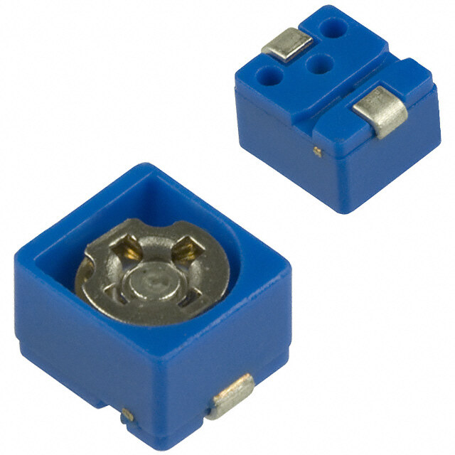
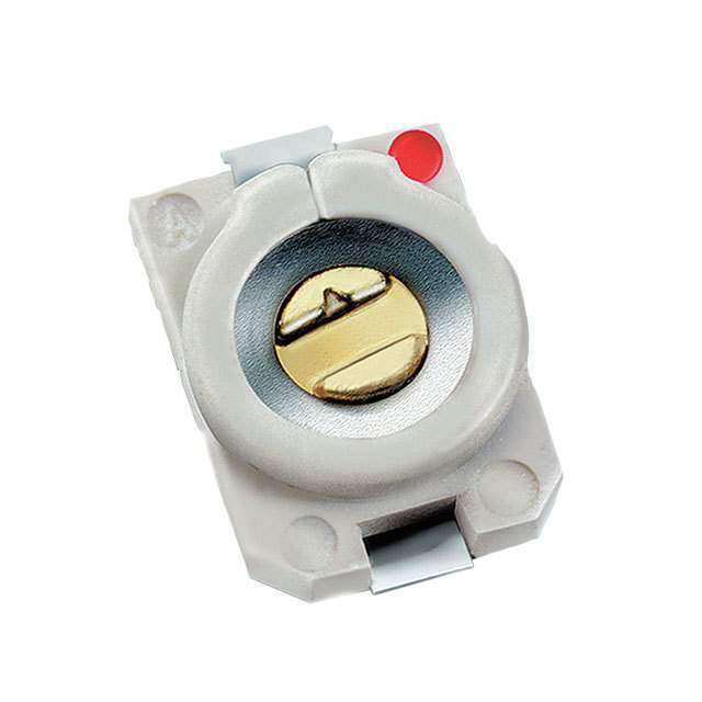
!Note (cid:129) Please read rating and !CAUTION (for storage, operating, rating, soldering, mounting and handling) in this catalog to prevent smoking and/or burning, etc. T13E.pdf (cid:129) This catalog has only typical specifications. Therefore, please approve our product specifications or transact the approval sheet for product specifications before ordering. Sep.1,2017 Ceramic Trimmer Capacitors TZB4 Series 0.6±0.1 Depth 0.5 1.4±0.1 dia. Features 1 2 0. 0. 1. Miniature rectangular shape: 2.4± 4.0± 4.0(W)x4.5(L)x3.0(H)mm. 4.5±0.2 2. Color coded case facilitates identification of 2 capacitance range. 0±0. 3. 3. Designed for automatic placement in surface mount applications. 2.7±0.3 1.2±0.1 4. Designed to withstand flux baths and solder baths A Type (with cover film type). 5. Can be temporarily attached to PCB with adhesives (Tolerance: ±0.5 ) 5.0 in mm (Terminal style A and B). 6. Can be reflow and flow (with cover film type) 0.6±0.1 Depth 0.5 1.4±0.1 dia. soldering method. 7. Stable characteristics over a wide frequency range. 1 2 0. 0. (Resonant frequency: 1000MHz min. / 6pF) 4± 0± 2. 4. 4.5±0.2 Applications 2 1. Car audio systems 0. 0± 2. Hybrid ICs 3. 3. Remote keyless entry systems 1.2±0.1 4. Surveillance cameras B Type 5. Burglarproof devices 5 (Tolerance: ±0.5 ) 6. Entry phone 7.0 in mm C min. (max.) C max. Withstanding Part Number TC Q Rated Voltage Stator/Case Color (pF) (pF) Voltage TZB4Z030pp10 1.4 3.0 +50/-0% NP0±200ppm/°C 300min. at 1MHz, Cmax 100Vdc 220Vdc Brown TZB4Z060pp10 2.0 6.0 +50/-0% NP0±200ppm/°C 500min. at 1MHz, Cmax. 100Vdc 220Vdc Blue TZB4Z100pp10 3.0 10.0 +50/-0% NP0±300ppm/°C 500min. at 1MHz, Cmax. 100Vdc 220Vdc White TZB4R200pp10 4.5 20.0 +50/-0% N750±400ppm/°C 500min. at 1MHz, Cmax 100Vdc 220Vdc Red TZB4P300pp10 6.5 30.0 +50/-0% N1200±500ppm/°C 300min. at 1MHz, Cmax 100Vdc 220Vdc Green TZB4P400pp10 8.5 40.0 +50/-0% N1200±500ppm/°C 300min. at 1MHz, Cmax 100Vdc 220Vdc Yellow TZB4Z250pp10 4.0 25.0 +100/-0% NP0±300ppm/°C 300min. at 1MHz, Cmax. 50Vdc 110Vdc Black+Marking TZB4R500pp10 7.0 50.0 +100/-0% N750±300ppm/°C 300min. at 1MHz, Cmax 50Vdc 110Vdc Black+Marking Insulation Resistance: 10000M ohm Torque: 1.5 to 9.8mNm Operating Temperature Range: -25 to +85°C First blank: Terminal Type Second blank: Cover film codes (A: not provided, B: provided) rex. TZB4Z100A B10: Terminal Type is A, and Cover film is provided. Construction Cover Film (Cover film type) Rotor Spring – Plastic Case Metal Rotor Ceramic Plate Stator Terminal Rotor Terminal + 21
!Note (cid:129) Please read rating and !CAUTION (for storage, operating, rating, soldering, mounting and handling) in this catalog to prevent smoking and/or burning, etc. T13E.pdf (cid:129) This catalog has only typical specifications. Therefore, please approve our product specifications or transact the approval sheet for product specifications before ordering. Sep.1,2017 Land Pattern/Mounting Holes A Type B Type 7.0+-00.5 8.0+-00.5 2.4±0.2 4.0±0.2 1 1.6±0. 1.6±0.1 (in mm) (in mm) Temperature Characteristics TZB4Z030 TZB4Z060 Z030 (NP0±200 ppm/°C) Z060 (NP0±200 ppm/°C) 8 8 6 6 4 4 2 2 –25 20 85 –25 20 85 Temp. (°C) Temp. (°C) –2 –2 –4 –4 %) %) e ( –6 e ( –6 g g an –8 an –8 h h C C p. –10 p. –10 a a 5 C–12 C–12 TZB4Z100 TZB4R200 Z100 (NP0±300 ppm/°C) R200 (N750±400 ppm/°C) 8 8 6 6 4 4 2 2 –25 20 85 –25 20 85 Temp. (°C) Temp. (°C) –2 –2 –4 –4 %) %) e ( –6 e ( –6 g g an –8 an –8 h h C C p. –10 p. –10 a a C–12 C–12 TZB4P300 TZB4P400 P300 (N1200±500 ppm/°C) P400 (N1200±500 ppm/°C) 8 8 6 6 4 4 2 2 –25 20 85 –25 20 85 Temp. (°C) Temp. (°C) –2 –2 –4 –4 %) %) e ( –6 e ( –6 g g an –8 an –8 h h C C p. –10 p. –10 a a C–12 C–12 Continued on the following page. 22
!Note (cid:129) Please read rating and !CAUTION (for storage, operating, rating, soldering, mounting and handling) in this catalog to prevent smoking and/or burning, etc. T13E.pdf (cid:129) This catalog has only typical specifications. Therefore, please approve our product specifications or transact the approval sheet for product specifications before ordering. Sep.1,2017 Continued from the preceding page. Temperature Characteristics TZB4Z250 TZB4R500 Z250 (NP0±300 ppm/°C) R500 (N750±300 ppm/°C) 8 8 6 6 4 4 2 2 –25 20 85 –25 20 85 Temp. (°C) Temp. (°C) –2 –2 –4 –4 %) %) e ( –6 e ( –6 g g an –8 an –8 h h C C p. –10 p. –10 a a C–12 C–12 Frequency Characteristics TZB4Z060 TZB4Z100 Z060 Z100 1000 1000 1000 1000 F) F) p p 100 100 ce ( 100 100 ce ( Q an Q an cit cit a a p p a a C C 10 10 10 10 1 100 200 300 400 500 600 700 800 900 1000 1 100 200 300 400 500 600 700 800 900 1000 5 Frequency (MHz) Frequency (MHz) TZB4R200 TZB4R500 R200 R500 1000 1000 1000 1000 pF) pF) Q 100 100 pacitance ( Q 100 100 pacitance ( Ca Ca 10 10 10 10 1 100 200 300 400 500 600 1 100 200 300 400 500 Frequency (MHz) Frequency (MHz) 23
!Note (cid:129) Please read rating and !CAUTION (for storage, operating, rating, soldering, mounting and handling) in this catalog to prevent smoking and/or burning, etc. T13E.pdf (cid:129) This catalog has only typical specifications. Therefore, please approve our product specifications or transact the approval sheet for product specifications before ordering. Sep.1,2017 Temperature Profile oFlow Soldering Profile Soldering profile for Lead-free solder (96.5Sn/3Ag/0.5Cu), Eutectic solder (63Sn/37Pb) C) T3 e (° T2 Standard Profile ur t2 eratT1 Limit Profile Pre-heating Heating Cycle mp Standard Profile Temp. (T1) Time (t1) Temp. (T2) Time (t2) of reflow e T 150°C 60 to 120sec. 250°C 5sec. max. 1 time t1 time (s) Limit Profile (cid:70)(cid:3)(cid:13)(cid:43)(cid:43)(cid:35)(cid:48)(cid:49)(cid:35)(cid:3)(cid:50)(cid:38)(cid:35)(cid:3)(cid:32)(cid:45)(cid:34)(cid:55)(cid:3)(cid:39)(cid:44)(cid:3)(cid:49)(cid:45)(cid:42)(cid:34)(cid:35)(cid:48)(cid:3)(cid:32)(cid:31)(cid:50)(cid:38)(cid:65)(cid:3)(cid:31)(cid:52)(cid:31)(cid:39)(cid:42)(cid:31)(cid:32)(cid:42)(cid:35)(cid:3)(cid:36)(cid:45)(cid:48)(cid:3)(cid:33)(cid:45)(cid:52)(cid:35)(cid:48)(cid:3)(cid:113)(cid:42)(cid:43)(cid:3)(cid:50)(cid:55)(cid:46)(cid:35)(cid:64) Pre-heating Heating Cycle Temp. (T1) Time (t1) Temp. (T3) Time (t2) of reflow 150°C 60 to 120sec. 265±3°C 5sec. max. 2 times oReflow Soldering Profile n1 Soldering profile for Lead-free solder (96.5Sn/3Ag/0.5Cu) n2 Soldering profile for Eutectic solder (63Sn/37Pb) (Limit profile: refer to n1 ) T5 C) T3 T4 C) T3 e (° T2 e (° urT1 ur T2 perat t2 Limit Profile peratT1 t2 Standard Profile em t3 Standard Profile em T T t1 time (s) t1 time (s) Standard Profile Standard Profile Pre-heating Heating Peak Cycle Pre-heating Heating Peak Cycle temperature temperature Temp. (T1) Time (t1) Temp. (T2) Time (t2) (T3) of reflow Temp. (T1) Time (t1) Temp. (T2) Time (t2) (T3) of reflow 150 to 180°C60 to 120sec. 220°C 30 to 60sec. 245±3°C 2 times 150°C 60 to 120sec. 183°C 30sec. 230 +5/-0°C 1 time 5 Limit Profile Pre-heating Heating Peak Cycle temperature Temp. (T1) Time (t1) Temp. (T4) Time (t3) (T5) of reflow 150 to 180°C60 to 120sec. 230°C 30 to 50sec.260 +5/-0°C 2 times (cid:70)(cid:3)(cid:5)(cid:52)(cid:31)(cid:39)(cid:42)(cid:31)(cid:32)(cid:42)(cid:35)(cid:3)(cid:36)(cid:45)(cid:48)(cid:3)(cid:50)(cid:35)(cid:48)(cid:43)(cid:39)(cid:44)(cid:31)(cid:42)(cid:3)(cid:49)(cid:38)(cid:31)(cid:46)(cid:35)(cid:3)(cid:5)(cid:65)(cid:3)(cid:6)(cid:65)(cid:3)(cid:31)(cid:44)(cid:34)(cid:3)(cid:9)(cid:64) oSoldering Iron Standard Profile Temperature of soldering iron tip Soldering time Soldering iron power output Cycle of soldering iron 350±10°C 3sec. max. 30W max. 1 time Notice (Storage and Operating Conditions) 1. Do not use the trimmer capacitor under atmosphere 6. Do not use the trimmer capacitor under the of RTV silicone rubber (Room Temperature conditions listed below. Vulcanizing Silicone Rubber) except Acetone (1) Corrosive gasses atmosphere liberating silicone sealant. (ex. Chlorine gas, Hydrogen sulfide gas, 2. Before using trimmer capacitors, please store under Ammonia gas, Sulfuric acid gas, Nitric oxide gas, the conditions of -10 to +40°C and 30 to etc.) 85%RH. (2) In liquid (ex. water, oil, medical liquid, 3. Do not store in or near corrosive gasses. organic solvent, etc.) 4. Use within 6 months of delivery. (3) Dusty / dirty atmosphere 5. Do not store under direct sunlight. (4) Direct sunlight (5) Static voltage or electric/magnetic fields (6) Direct sea breeze (7) Other variations of the above 24
!Note (cid:129) Please read rating and !CAUTION (for storage, operating, rating, soldering, mounting and handling) in this catalog to prevent smoking and/or burning, etc. T13E.pdf (cid:129) This catalog has only typical specifications. Therefore, please approve our product specifications or transact the approval sheet for product specifications before ordering. Sep.1,2017 Notice (Soldering and Mounting) 1. Soldering 2. Mounting (1) Can be soldered by reflow soldering method, flow (1) Do not apply excessive force (preferably 5.0N soldering method, and soldering iron. [Ref: 500gf] max.), when the trimmer capacitor (2) Soldering conditions is mounted on the PCB. Refer to the temperature profile. (2) Do not warp and/or bend PCB to protect trimmer If the soldering conditions are not suitable, e.g., capacitor from breakage. excessive time and/or excessive temperature, the (3) When bending the terminals, do not apply trimmer capacitor may deviate from the specified excessive force to the body of the product to characteristics. protect the terminal fixing part from damage. (3) The amount of solder is critical. (4) Use a pick-up nozzle of a suitable dimension. (4) The thickness of solder paste should be printed > Without cover film type from 150 micro m to 200 micro m and the dimension - External dimensions of 4.5x4.0mm and of land pattern should be Murata's standard land 2.5mm bore diameter. pattern used at reflow soldering. Insufficient > With cover film type amounts of solder can lead to insufficient - 4.0mm external diameter and 2.0mm bore soldering strength on PCB. Excessive amounts of diameter. solder may cause bridging between the terminals 3. Cleaning [with cover film type] or contact failure due to flux wicking up. Isopropyl alcohol and ethyl alcohol are available (5) When using soldering iron, the string solder material for cleaning. If you use any other type of shall be applied to the lower part of the solvent, please evaluate performance in your terminal only. Do not apply flux except to the application. Moreover, please confirm that no terminals. Excessive amounts of solder and/or damage has occurred to the trimmer capacitor applying solder to the upper part of the after cleaning in your conditions. terminal may cause fixed rotor or contact failure 4. Other due to flux invasion into the movable part and/or Note the polarity of the trimmer capacitor to the contact point. The soldering iron should not minimize influence by stray capacitance. come in contact with the plastic case of the (Refer to the dimensions concerning the polarity.) trimmer capacitor. If such contact does occur, 5 the trimmer capacitor may be damaged. (6) Our recommended chlorine content of solder is as follows. (a) Solder paste: 0.2wt% max. (b) String solder: 0.5wt% max. (7) Do not use water-soluble flux (for water cleaning). To prevent the deterioration of trimmer capacitor characteristics, apply flux only to terminals. Notice (Handling) 1. Use suitable screwdrivers that fit comfortably in 3. Do not apply adhesive, lock paints, or any other driver slot. substances to the trimmer capacitor to secure the (1) Recommended screwdriver for manual adjustment rotor position. They may cause corrosion or MURATA: KMDR010 electrical contact problems. (2) Recommended screwdriver bit for automatic 4. Do not break the cover film before the completion adjustment of PCB mounting, soldering, and cleaning. MURATA: KMBT010 5. Do not clean the trimmer capacitor after the cover 2. When adjusting with a screwdriver, do not apply film has been broken. excessive force (preferably 1.0 N [Ref: 100gf] max.) 6. To break the cover film, first turn the screwdriver to minimize capacitance drift. Excessive force applied more than 360°, and set the capacitance value. to the screwdriver slot may cause deformation of the (Inserting the screwdriver only will not break the products. cover film.) Notice (Other) Before using trimmer capacitors, please test after assembly in your particular mass production system. 25
!Note (cid:129) Please read rating and !CAUTION (for storage, operating, rating, soldering, mounting and handling) in this catalog to prevent smoking and/or burning, etc. T13E.pdf (cid:129) This catalog has only typical specifications. Therefore, please approve our product specifications or transact the approval sheet for product specifications before ordering. Sep.1,2017 Packaging Minimum Quantity Minimum Quantity (pcs.) Part Number ø180mm Reel ø330mm Reel Bulk TZR1 3000 - 500 TZY2 2000 - 500 TZC3 1000 - 500 TZW4 500 - 100 TZB4 500 2500 500 Tape Dimensions TZR1 Series TZY2 Series 1.5+-00.1dia. 2.0 4.0 t 2.0±0.1 5 0.25 4.0±0.1 4.0±0.1 1.05±0.2 A 1.7 1.5+-00.1dia. 0.25±0.1 2.0±0.2 3.5±0.1 1.75±0.1 8.0±0.3 3.6±0.2 A 3.5 8.0±0.2 A s-eAcctrioonss 2.7±0.2 1.8±0.2 4.0 t=TZY2 (TZVY2): 1.6±0.2 (Tolerance: ±0.1 ) (in mm) in mm TZC3 Series TZW4 Series 1.5+-00.1dia. 2.0±0.2 1.5+-00.1dia. 2.6 A 2 4 1.75 0.3 A 2 4 1.75 0.3 9±0.2 5.5 12±0.3 5.6 5.5 12±0.2 4. A A-Across A A-Across 8 3.6±0.2 section 8 4.6 section (Tolerance: ±0.1 ) (Tolerance: ±0.1 ) in mm in mm TZB4 Series 1.5+-00.1dia. 3.55±0.2 A 8.0 2.0 4 .0 75 0.3±0.1 1. 5.5 0±0.3 4.87.5 12. 1.8 A-Across A section 4.3 Direction of feed (Tolerance: ±0.1 ) in mm Continued on the following page. 26
!Note (cid:129) Please read rating and !CAUTION (for storage, operating, rating, soldering, mounting and handling) in this catalog to prevent smoking and/or burning, etc. T13E.pdf (cid:129) This catalog has only typical specifications. Therefore, please approve our product specifications or transact the approval sheet for product specifications before ordering. Sep.1,2017 Packaging Continued from the preceding page. Reel Dimensions (180mm diameter) TZR1/TZY2 Series TZC3/TZW4/TZB4 Series 13.0±0.5 dia. 13.0±0.5 dia. 2.0±0.5 min. 2.0±0.5 min. 21.0±0.8 dia. 50 21.0±0.8 dia. 50 9.0±1.0 13.0±1.0 13.0±1.0 17.0±1.0 178±2 dia. 178±2 dia. (in mm) (in mm) Reel Dimensions (330mm diameter) TZB4 Series 13.0±0.5 dia. 2.0±0.5 min. 21.0±0.8 dia. 50 13.5±1.0 17.5±1.0 328±2 dia. (in mm) 27
!Note (cid:129) Please read rating and !CAUTION (for storage, operating, rating, soldering, mounting and handling) in this catalog to prevent smoking and/or burning, etc. T13E.pdf (cid:129) This catalog has only typical specifications. Therefore, please approve our product specifications or transact the approval sheet for product specifications before ordering. Sep.1,2017 Recommended Adjustment Tools Please use the following recommended screwdrivers. You can order these drivers using the part numbers below. Although you can also adjust the capacitance value using commercial products, please use one with the same head size as the driver listed below. For Manual Adjustment MURATA Manufacturer’s Series Shape Model Number Model Number 80 1.5 MURATA MFG. TZR1 KMDR160 KMDR160 Bit shape: Minus (0.3x0.13) (in mm) 125 15 VESSEL MFG. TZY2 KMDR020 NO.9000 -0.9x30 Bit shape: Minus (0.9x30) (in mm) 125 15 VESSEL MFG. TZC3 KMDR080 NO.9000 +1.7x30 Bit shape: Plus (1.7x30) (in mm) 122 20 50 MURATA MFG. TZB4 KMDR010 KMDR010 Bit shape: Minus (2.2x0.4) (in mm) 125 15 VESSEL MFG. TZW4 KMDR130 NO.9000 -1.3x30 Bit shape: Minus (1.3x30) (in mm) For Automatic Adjustment MURATA Manufacturer’s Series Shape Model Number Model Number 5 TZY2 KMBT020 MURATA MFG. ø2.4 3.0 5.0 0.2±0.0 0.9±0ø2.0.05 0.4±0.05 KMBT020 0.6±0.05 10.0 (in mm) 25.0 30 MURATA MFG. TZB4 KMBT010 KMBT010 a. Bit shape: Minus (2.2x0.4) 2 di 2. (in mm) 28
!Note (cid:129) Please read rating and !CAUTION (for storage, operating, rating, soldering, mounting and handling) in this catalog to prevent smoking and/or burning, etc. T13E.pdf (cid:129) This catalog has only typical specifications. Therefore, please approve our product specifications or transact the approval sheet for product specifications before ordering. Sep.1,2017 Qualified Standards The products listed herein have been produced by a ISO9001 certified factory. MURATA FACTORY Sabae Murata Mfg. Co., Ltd. * No ODCs (Ozone Depleting Chemicals) are used on any Murata trimmer capacitors. 29
T13E.pdf Sep.1,2017 Cat. No. T13E-17 Global Locations For details please visit www.murata.com Note 1 Export Control 2 Please contact our sales representatives or 3 Product specifi cations in this catalog are as of product engineers before using the products in September 2017. They are subject to change or For customers outside Japan: this catalog for the applications listed below, our products in it may be discontinued without No Murata products should be used or which require especially high reliability for the advance notice. Please check with our sales sold, through any channels, for use in the prevention of defects which might directly representatives or product engineers before design, development, production, utilization, damage a third party’s life, body or property, or ordering. If there are any questions, please contact maintenance or operation of, or otherwise when one of our products is intended for use our sales representatives or product engineers. contribution to (1) any weapons (Weapons of in applications other than those specified in Mass Destruction [nuclear, chemical or biological this catalog. 4 Please read rating and CAUTION (for storage, weapons or missiles] or conventional weapons) operating, rating, soldering, mounting and or (2) goods or systems specially designed or 1 Aircraft equipment handling) in this catalog to prevent smoking intended for military end-use or utilization by 2 Aerospace equipment and/or burning, etc. military end-users. For customers in Japan: 3 Undersea equipment 5 TThheisr ecfaotraelo, pgl ehaasse o anplyp tryopveic aolu srp percoidfi uccatt ions. 4 Power plant equipment specifi cations or transact the approval sheet For products which are controlled items subject for product specifi cations before ordering. to the “Foreign Exchange and Foreign Trade Law” 5 Medical equipment of Japan, the export license specifi ed by the law 6 Please note that unless otherwise specifi ed, we is required for export. 6 Transportation equipment (vehicles, trains, shall assume no responsibility whatsoever for any ships, etc.) confl ict or dispute that may occur in connection 7 Traffi c signal equipment with the eff ect of our and/or a third party’s intellectual property rights and other related 8 Disaster prevention / crime prevention rights in consideration of your use of our products equipment and/or information described or contained in our catalogs. In this connection, no representation 9 Data-processing equipment shall be made to the eff ect that any third parties are authorized to use the rights mentioned above 10 Application of similar complexity and/or under licenses without our consent. reliability requirements to the applications listed above 7 No ozone depleting substances (ODS) under the Montreal Protocol are used in our manufacturing process. Murata Manufacturing Co., Ltd. www.murata.com