ICGOO在线商城 > TXD2SA-5V-Z
 Datasheet下载
- 型号: TXD2SA-5V-Z
- 制造商: Panasonic Corporation
- 库位|库存: xxxx|xxxx
- 要求:
| 数量阶梯 | 香港交货 | 国内含税 |
| +xxxx | $xxxx | ¥xxxx |
查看当月历史价格
查看今年历史价格
TXD2SA-5V-Z产品简介:
ICGOO电子元器件商城为您提供TXD2SA-5V-Z由Panasonic Corporation设计生产,在icgoo商城现货销售,并且可以通过原厂、代理商等渠道进行代购。 提供TXD2SA-5V-Z价格参考以及Panasonic CorporationTXD2SA-5V-Z封装/规格参数等产品信息。 你可以下载TXD2SA-5V-Z参考资料、Datasheet数据手册功能说明书, 资料中有TXD2SA-5V-Z详细功能的应用电路图电压和使用方法及教程。
| 参数 | 数值 |
| 产品目录 | |
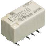
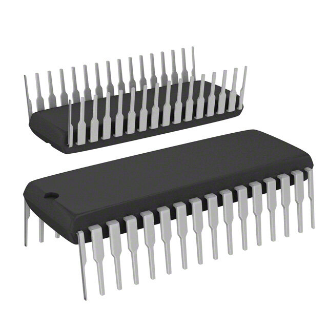
| 描述 | RELAY GEN PURPOSE DPDT 2A 5V低信号继电器 - PCB 2 AMP 5VDC DPDT |
| 产品分类 | |
| 品牌 | Panasonic Electric Works |
| 产品手册 | |
| 产品图片 |
|
| rohs | RoHS 合规性豁免无铅 / 符合限制有害物质指令(RoHS)规范要求 |
| 产品系列 | 低信号继电器 - PCB,Panasonic Industrial Devices TXD2SA-5V-ZTX-D |
| mouser_ship_limit | 该产品可能需要其他文件才能进口到中国。 |
| 数据手册 | |
| 产品型号 | TXD2SA-5V-Z |
| 产品 | Low Profile Relays |
| 产品目录绘图 |
|
| 产品目录页面 | |
| 产品种类 | 低信号继电器 - PCB |
| 介入损耗 | 0.8 dB at 1 GHz |
| 关闭电压(最小值) | 0.5 VDC |
| 其它名称 | 255-2327-6 |
| 其它有关文件 | |
| 功耗 | 200 mW |
| 包装 | Digi-Reel® |
| 商标 | Panasonic Industrial Devices |
| 安装类型 | 表面贴装 |
| 安装风格 | Through Hole |
| 导通电压(最大值) | 3.75 VDC |
| 封装 | Reel |
| 工作时间 | 4ms |
| 工作温度 | -40°C ~ 85°C |
| 工厂包装数量 | 500 |
| 开关电压 | 220VDC - 最小值 |
| 最大开关电流 | 2 A |
| 标准包装 | 1 |
| 特性 | 密封式 - 全部 |
| 端子类型 | 鸥翼型 |
| 端接类型 | Solder Pin |
| 线圈功率 | 200 mW |
| 线圈电压 | 5VDC |
| 线圈电流 | 40mA |
| 线圈电阻 | 125 欧姆 |
| 线圈类型 | 无锁存 |
| 绝缘 | 20 dB at 1 GHz |
| 继电器类型 | 通用 |
| 触头外形 | DPDT(2 C 型) |
| 触头材料 | Silver(Ag),Gold(Au) |
| 触点形式 | DPDT (2 Form C) |
| 触点电流额定值 | 2 A |
| 触点额定值 | 2 A at 30 VDC |
| 释放时间 | 4ms |
| 额定接触(电流) | 2A |


- 商务部:美国ITC正式对集成电路等产品启动337调查
- 曝三星4nm工艺存在良率问题 高通将骁龙8 Gen1或转产台积电
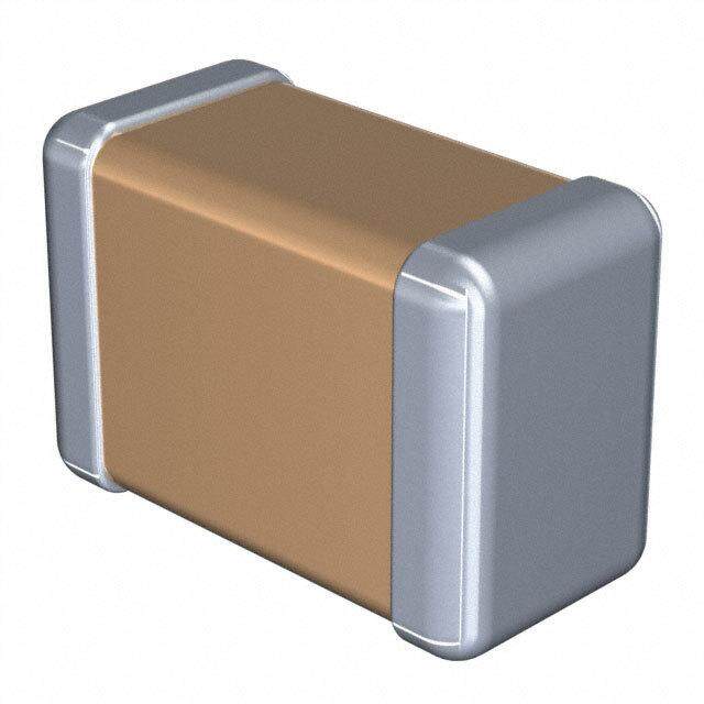
- 太阳诱电将投资9.5亿元在常州建新厂生产MLCC 预计2023年完工
- 英特尔发布欧洲新工厂建设计划 深化IDM 2.0 战略
- 台积电先进制程称霸业界 有大客户加持明年业绩稳了
- 达到5530亿美元!SIA预计今年全球半导体销售额将创下新高
- 英特尔拟将自动驾驶子公司Mobileye上市 估值或超500亿美元
- 三星加码芯片和SET,合并消费电子和移动部门,撤换高东真等 CEO
- 三星电子宣布重大人事变动 还合并消费电子和移动部门
- 海关总署:前11个月进口集成电路产品价值2.52万亿元 增长14.8%


PDF Datasheet 数据手册内容提取
6,000 V Surge breakdown voltage, 2 Form C, 2 A TX-D RELAYS and High breakdown voltage type relays FEATURES 1.Approved to the supplementary 5.High contact reliability insulation class in the EN standards High contact reliability is achieved by (EN60950). the use of gold-clad twin crossbar The insulation distance between the contacts, low-gas formation materials, contact and coil meet the mold sealing the coil section, and by supplementary insulation class of the controlling organic gas in the coil. EN60950 standards as required for *We also offer a range of products equipment connected to the telephone with AgPd contacts suitable for use lines in Europe. in low level load analog circuits Satisfies the following conditions: (Max. 10V DC 10 mA). RoHS compliant • Clearances: 2.0 mm .079 inch or more TYPICAL APPLICATIONS • Creepage distance: 2.5 mm .098 inch or more 1.Facsimile 2.3,000 V breakdown voltage between 2.Modem contact and coil. 3.Communications (xDSL) 3.Nominal operating power: 4.Medical equipment High sensitivity of 200mW 5.Security 4.High contact capacity: 2 A 30 V DC ORDERING INFORMATION TXD 2 Contact arrangement 2: 2 Form C Surface-mount availability Nil: Standard PC board terminal SA:SA type Operating function Nil: Single side stable L: 1 coil latching Type of operation Nil: Standard type 2M:M.B.B. type Nominal coil voltage (DC) 3, 4.5, 5, 6, 9, 12, 24V Contact material Nil:Standard contact (Ag+Au clad) 1: AgPd contact (low level load); AgPd+Au clad (stationary), AgPd (movable) Packing style Nil:Tube packing X: Tape and reel (picked from 1/3/4/5-pin side) Z: Tape and reel packing (Picked from the 8/9/10/12-pin side) Note:In case of 5 V transistor drive circuit, it is recommended to use 4.5 V type relay. –1– ASCTB19E 201407-T
TX-D TYPES 1. Standard (B.B.M.) type 1) Standard PC board terminal Contact Nominal coil Single side stable 1 coil latching arrangement voltage Part No. Part No. 3 V DC TXD2-3V TXD2-L-3V 4.5 V DC TXD2-4.5V TXD2-L-4.5V 5 V DC TXD2-5V TXD2-L-5V 2 Form C 6 V DC TXD2-6V TXD2-L-6V 9 V DC TXD2-9V TXD2-L-9V 12 V DC TXD2-12V TXD2-L-12V 24 V DC TXD2-24V TXD2-L-24V Standard packing: Tube: 40 pcs.; Case: 1,000 pcs. Note: Please add “-1” to the end of the part number for AgPd contacts (low level load). 2) Surface-mount terminal (1) Tube packing Contact Nominal coil Single side stable 1 coil latching arrangement voltage Part No. Part No. 3 V DC TXD2SA-3V TXD2SA-L-3V 4.5 V DC TXD2SA-4.5V TXD2SA-L-4.5V 5 V DC TXD2SA-5V TXD2SA-L-5V 2 Form C 6 V DC TXD2SA-6V TXD2SA-L-6V 9 V DC TXD2SA-9V TXD2SA-L-9V 12 V DC TXD2SA-12V TXD2SA-L-12V 24 V DC TXD2SA-24V TXD2SA-L-24V Standard packing: Tube: 40 pcs.; Case: 1,000 pcs. Note: Please add “-1” to the end of the part number for AgPd contacts (low level load). (2) Tape and reel packing Contact Nominal coil Single side stable 1 coil latching arrangement voltage Part No. Part No. 3 V DC TXD2SA-3V-Z TXD2SA-L-3V-Z 4.5 V DC TXD2SA-4.5V-Z TXD2SA-L-4.5V-Z 5 V DC TXD2SA-5V-Z TXD2SA-L-5V-Z 2 Form C 6 V DC TXD2SA-6V-Z TXD2SA-L-6V-Z 9 V DC TXD2SA-9V-Z TXD2SA-L-9V-Z 12 V DC TXD2SA-12V-Z TXD2SA-L-12V-Z 24 V DC TXD2SA-24V-Z TXD2SA-L-24V-Z Standard packing: Tape and reel: 500 pcs.; Case: 1,000 pcs. Notes:1.Tape and reel packing symbol “-Z” is not marked on the relay. “X” type tape and reel packing (picked from 1/3/4/5-pin side) is also available. 2.Please add “-1” to the part number for AgPd contacts (low level load). (Ex. TXD2SA-3V-1-Z) 2. M.B.B type 1) Standard PC board terminal Single side stable Contact arrangement Nominal coil voltage Part No. 3 V DC TXD2-2M-3V 4.5 V DC TXD2-2M-4.5V 5 V DC TXD2-2M-5V 2 Form C 6 V DC TXD2-2M-6V 9 V DC TXD2-2M-9V 12 V DC TXD2-2M-12V 24 V DC TXD2-2M-24V Standard packing: Tube: 40 pcs.; Case: 1,000 pcs. –2– ASCTB19E 201407-T
TX-D 2) Surface-mount terminal (1) Tube packing Single side stable Contact arrangement Nominal coil voltage Part No. 3 V DC TXD2SA-2M-3V 4.5 V DC TXD2SA-2M-4.5V 5 V DC TXD2SA-2M-5V 2 Form C 6 V DC TXD2SA-2M-6V 9 V DC TXD2SA-2M-9V 12 V DC TXD2SA-2M-12V 24 V DC TXD2SA-2M-24V Standard packing: Tube: 40 pcs.; Case: 1,000 pcs. (2) Tape and reel packing Single side stable Contact arrangement Nominal coil voltage Part No. 3 V DC TXD2SA-2M-3V-Z 4.5 V DC TXD2SA-2M-4.5V-Z 5 V DC TXD2SA-2M-5V-Z 2 Form C 6 V DC TXD2SA-2M-6V-Z 9 V DC TXD2SA-2M-9V-Z 12 V DC TXD2SA-2M-12V-Z 24 V DC TXD2SA-2M-24V-Z Standard packing: Tape and reel: 500 pcs.; Case: 1,000 pcs. Notes:1.Types designed to withstand strong vibration caused, for example, by the use of terminal cutters, can also be ordered. However, please contact us if you need parts for use in low level load. (Ex. TXD2SA-2M-3V-1-Z) 2.Tape and reel packing symbol “-Z” is not marked on the relay. “X” type tape and reel packing (picked from 1/3/4/5-pin side) is also available. RATING 1. Coil data [Standard (B.B.M.) type] 1) Single side stable Nominal operating Nominal coil Pick-up voltage Drop-out voltage Coil resistance Nominal operating Max. applied voltage voltage (at 20°C 68°F) (at 20°C 68°F) [±10%] c(autr r2e0n°tC 68°F) [±10%] (at 20°C 68°F) power (at 20°C 68°F) 3 V DC 66.7 mA 45 Ω 4.5 V DC 44.4 mA 101 Ω 56 VV DDCC n7o5m%inVa ol rv oleltsasg oef* 1n0o%mVin aolr vmolotareg eo*f 4303..03 mmAA 112850 ΩΩ 200 mW 120%V of nominal voltage 9 V DC (Initial) (Initial) 22.2 mA 405 Ω 12 V DC 16.7 mA 720 Ω 24 V DC 9.6 mA 2,504 Ω 230 mW 2) 1 coil latching Nominal operating Nominal coil Set voltage Reset voltage Coil resistance Nominal operating Max. applied voltage voltage (at 20°C 68°F) (at 20°C 68°F) [±10%] c(autr r2e0n°tC 68°F) [±10%] (at 20°C 68°F) power (at 20°C 68°F) 3 V DC 50.0 mA 60 Ω 4.5 V DC 33.3 mA 135 Ω 56 VV DDCC n7o5m%inVa ol rv oleltsasg oef* n7o5m%inVa ol rv oleltsasg oef* 3205..00 mmAA 126460 ΩΩ 150 mW 120%V of nominal voltage 9 V DC (Initial) (Initial) 16.7 mA 540 Ω 12 V DC 12.5 mA 960 Ω 24 V DC 7.1 mA 3,388 Ω 170 mW [M.B.B. type] Nominal operating Nominal coil Pick-up voltage Drop-out voltage Coil resistance Nominal operating Max. applied voltage voltage (at 20°C 68°F) (at 20°C 68°F) [±10%] c(autr r2e0n°tC 68°F) [±10%] (at 20°C 68°F) power (at 20°C 68°F) 3 V DC 83.3 mA 36 Ω 4.5 V DC 55.6 mA 81 Ω 56 VV DDCC n7o5m%inVa ol rv oleltsasg oef* 1n0o%mVin aolr vmolotareg eo*f 5401..07 mmAA 110404 ΩΩ 250 mW 120%V of nominal voltage 9 V DC (Initial) (Initial) 27.8 mA 324 Ω 12 V DC 20.8 mA 576 Ω 24 V DC 11.3 mA 2,133 Ω 270 mW *Pulse drive (JIS C 5442-1986) –3– ASCTB19E 201407-T
TX-D 2. Specifications Characteristics Item Specifications Arrangement 2 Form C 2 Form D (M.B.B.type) Contact resistance (Initial) Max. 100 mΩ (By voltage drop 6 V DC 1A) Contact Standard contact: Ag+Au clad, Contact material AgPd contact (low level load): AgPd+Au clad (stationary), AgPd (movable) Standard contact: 2 A 30 V DC, Nominal switching capacity 1 A 30 V DC (resistive load) AgPd contact: 1 A 30 V DC (resistive load) Standard contact: 60 W (DC), Max. switching power 30 W (DC) (resistive load) AgPd contact: 30 W (DC) (resistive load) Rating Max. switching voltage 220 V DC 110 V DC Max. switching current Standard contact: 2 A, AgPd contact: 1 A 1 A Min. switching capacity (Reference value)*1 10μA10mV DC Nominal operating Single side stable 200mW (3 to 12 V DC), 230mW (24 V DC) 250mW (1.5 to 12 V DC), 270mW (24 V DC) power 1 coil latching 150mW (3 to 12 V DC), 170mW (24 V DC) — Insulation resistance (Initial) Min. 1,000MΩ (at 500V DC) Measurement at same location as “Initial breakdown voltage” section. Between open contacts 1,000 Vrms for 1min. (Detection current: 10mA) 500 Vrms for 1min. (Detection current: 10mA) Breakdown Between contact and coil 3,000 Vrms for 1min. (Detection current: 10mA) 3,000 Vrms for 1min. (Detection current: 10mA) voltage (Initial) Between contact sets 1,000 Vrms for 1min. (Detection current: 10mA) Between open contacts 1,500 V (10×160μs) (FCC Part 68) — Surge breakdown Electrical voltage (Initial) Between contacts and 6,000 V, 1.2 × 50μs characteristics coil*1 Max. 50°C 122°F Temperature rise (at 20°C 68°F) (By resistive method, nominal coil voltage applied to the coil; contact carrying current: 2A [1A: M.B.B.].) Operate time [Set time] (at 20°C 68°F) Max. 4 ms [Max. 4 ms] (Nominal coil voltage applied to the coil, excluding contact bounce time.) Release time [Reset time] (at 20°C 68°F) Max. 4 ms [Max. 4 ms] (Nominal coil voltage applied to the coil, excluding contact bounce time.) (without diode) Min. 750 m/s2 Min. 500 m/s2 Shock Functional (Half-wave pulse of sine wave: 6 ms; (Half-wave pulse of sine wave: 11 ms; Mechanical resistance detection time: 10μs.) detection time: 10μs.) characteristics Destructive Min. 1,000 m/s2 {100G} (Half-wave pulse of sine wave: 6 ms.) Vibration Functional 10 to 55 Hz at double amplitude of 3.3 mm (Detection time: 10μs.) resistance Destructive 10 to 55 Hz at double amplitude of 5 mm Mechanical Min. 108 (at 180 cpm) Min. 107 (at 180 cpm) Expected life Min. 105 (2 A 30 V DC resistive), Electrical (Standard contact) Min. 5×10⁵ (1 A 30 V DC resistive) (at 20 cpm) Min. 105 (1 A 30 V DC resistive) (at 20 cpm) Conditions for operation, transport and Ambient temperature: –40°C to +85°C –40°F to +185°F; Conditions storage*2 Humidity: 5 to 85% R.H. (Not freezing and condensing at low temperature) Max. operating speed (at rated load) 20 cpm Unit weight Approx. 2 g .071 oz Notes:*1 This value can change due to the switching frequency, environmental conditions, and desired reliability level, therefore it is recommended to check this with the actual load. AgPd contact type is available for low level load switching (10V DC, 10mA max. level). *2 The upper operation ambient temperature limit is the maximum temperature that can satisfy the coil temperature rise value. Refer to “AMBIENT ENVIRONMENT” in GENERAL APPLICATION GUIDELINES. REFERENCE DATA 1. Maximum switching capacity 2. Life curve 3. Mechanical life Tested sample: TXD2-5V, 10 pcs. Operating speed: 180 cpm V100 % 3.0 e, 90 g Switching current, A 00012.....34500 DC resistive load ×4No. of operations 10105320000 3re0sVis DtivCe load o against the rated volta 345678000000 PDircokp--uopu vt ovlotaltgaege MMMaianxx... 0.2 10 Rati 20 Min. 10 0 20 30 50 100 200300 0 1.0 2.0 00 10 100 1000 10000 Contact voltage, V Switching current, A No. of operations, ×104 –4– ASCTB19E 201407-T
TX-D 4. Electrical life (2 A 30 V DC resistive load) 5-(1). Coil temperature rise Tested sample: TXD2-5V, 6 pcs. Tested sample: TXD2-5V, 6 pcs. Operating speed: 20 cpm Measured portion: Inside the coil Change of pick-up and drop-out voltage Change of contact resistance Ambient temperature: 25°C 77°F, 70°C 158°F V100 100 70 % +25°C+77°F e, 90 90 +70°C+158°F g 60 Ratio against the rated volta 23456780000000 PDircokp--uopu vt ovlotaltgaege MMMMaiainnxx.... ΩContact resistance, m 23456780000000 MMainx.. °Temperature rise, C 54320000 2002AAAA 10 10 10 0 0 0 0 2 4 6 8 10 0 2 4 6 8 10 100 110 120 No. of operations, ×104 No. of operations, ×104 Coil applied voltage, %V 5-(2). Coil temperature rise 6-(1). Operate/release time characteristics 6-(2). Operate/release time characteristics Tested sample: TXD2-24V, 6 pcs. (with diode) (without diode) Measured portion: Inside the coil Tested sample: TXD2-5V, 10 pcs. Tested sample: TXD2-5V, 10 pcs. Ambient temperature: 25°C 77°F, 70°C 158°F 70 5 5 +25°C+77°F Operate time Operate time °Temperature rise, C 6543200000 2002AAAA+70°C+158°F Operate and release time, ms 243 MMMMaaiinnxx.... Release time Operate and release time, ms 243 MMMMaaiinxnx.... Release time 1 1 10 0 0 0 100 110 120 70 80 90 100 110 120 70 80 90 100 110 120 Coil applied voltage, %V Coil applied voltage, %V Coil applied voltage, %V 7. Ambient temperature characteristics 8. High-frequency characteristics 9. High-frequency characteristics Tested sample: TXD2-5V, 5 pcs. (Isolation) (Insertion loss) Tested sample: TXD2-12V, 2 pcs. Tested sample: TXD2-12V, 2 pcs. % o, 40 ati –40 –20 0 Variation r 2200Am40bien6t 0temxxP8pDic0erkor-apu-ptou uvrote lvt,ao °gltCaege Isolation, dB15000 Insertion loss, dB010...608 –20 0.4 –40 0.2 0 10 100 1,000 0 10 100 1,000 Frequency, MHz Frequency, MHz 10. Malfunctional shock (single side stable) 11-(1). Influence of adjacent mounting 11-(2). Influence of adjacent mounting Tested sample: TXD2-5V, 6 pcs Tested sample: TXD2-12V, 6 pcs. Tested sample: TXD2-12V, 6 pcs. 100YY0'Z'mX/sZ2XX1'000m/s2Y DcEoneneedrn1giet0Ziiozr0gen0idzm ec/dso2ndition Rate of change, %–505 Pick-up voltage ONONON Rate of change, %–505 Pick-up voltage OONNON 1000mZ/s'2 Y1'000m/s2 1X00'0m/s2 Rate of change, %–505 Drop-out voltage OFFOFOFFF Rate of change, %–505 Drop-out voltage OOFFFFOFF 0 2 4 6 8 10 0 2 4 6 8 10 .079.157.236.315.394 .079.157.236.315.394 Inter-relay distance , mminch Inter-relay distance , mminch –5– ASCTB19E 201407-T
TX-D 12. Actual load test (35 mA 48 V DC wire spring relay load) Tested sample: TXD2-5V, 6 pcs. Change of pick-up and drop-out voltage Change of contact resistance 100 100 V % Circuit age, 8900 Ωm 8900 48+– V DC0μ.0F8445588 ΩΩ0μ.0F8Wire spring relay 43TXD Ratio against the rated volt 234567000000 PDircokp--uopu vt ovlotaltgaege MMMMaiainnxx.... Contact resistance, 234567000000 MMianx.. 10 10 0 0 0 10 20 30 40 50 0 10 20 30 40 50 No. of operation, ×104 No. of operation, ×104 13-(1). Distribution of M.B.B. time Tested sample: TXD2-2M-5V, 50 pcs. Terminal No. 3-4-5: ON Terminal No. 3-4-5: OFF 60 60 x: 300.5 μs x: 298.8 μs 50 σn-1: 55.3 μs 50 σn-1: 51.8 μs Min.:165 μs Min.:205 μs Max.:415 μs Max.:432 μs 40 40 30 30 22 20 20 16 12 12 13 10 7 6 10 8 2 1 1 0 0 100 150 200 250 300 350 400μs min. 100 150 200 250 300 350 400μs min. 1~50 2~00 2~50 3~00 3~50 4~00 4~50μs max. 1~50 2~00 2~50 3~00 3~50 4~00 4~50μs max. 13-(2). Distribution of M.B.B. time 14. Surge breakdown voltage test Tested sample: TXD2-2M-5V, 50 pcs. Tested sample: TXD2-3V, 30 pcs. Terminal No. 8-9-10: ON Terminal No. 8-9-10: OFF 60 60 14 x: 293.4 μs x: 281.4 μs 50 σMni-n1:.:6105.54 μμss 50 σMni-n1:.:5182.03 μμss 12 Max.:445 μs Max.:421 μs 10 40 40 8 30 30 6 20 18 20 19 15 4 10 10 10 4 5 3 10 4 6 4 2 1 1 0 100 150 200 250 300 350 400μs min. 0 100 150 200 250 300 350 400μs min. 7000072007400760078008000820084008600 1~50 2~00 2~50 3~00 3~50 4~00 4~50μs max. 1~50 2~00 2~50 3~00 3~50 4~00 4~50μs max. Surge breakdown voltage, V DIMENSIONS (mm inch) The CAD data of the products with a CAD Data mark can be downloaded from: http://industrial.panasonic.com/ac/e/ 1) Standard PC board terminal CAD Data External dimensions PC board pattern Schematic (Bottom view) Standard PC board terminal (Bottom view) Single side stable 1 coil latching 1.559.010 7.2.4901 2.54 1.04.0106 +1 3 4 5 −1 3 4 5 0.65 .100 .0268.20 .323 5.08 − + .200 12 10 9 8 12 10 9 8 0.50 .020 0.25 8-1.0 dia. Direction indication Direction indication 1.15 5.08 2.54 3.50 5.08 .010 8-.039 dia. .045 .200 .100 .138 .200 Tolerance: ±0.1 ±.004 (Deenergized condition) (Reset condition) –6– ASCTB19E 201407-T
TX-D 2) Surface-mount terminal CAD Data External dimensions (General tolerance: ±0.3 ±.012) Suggested mounting pad (Top view) (Tolerance: ±0.1 ±.004) Type Single side stable and 1 coil latching Single side stable and 1 coil latching 15 7.4 5.08 2.54 .591 .291 1 .200 .100 8.2 8.4 .31.2146.039 .323 .331 SA type 0.25 0.5 0.0.6256 5.2.0080 .010 7.2.2845 .020 5.08 2.54 9.4±0.5 .200 .100 .370±.020 Schematic (Top view) Single side stable 1 coil latching −12 10 9 8 +12 10 9 8 + − 1 3 4 5 1 3 4 5 Direction indication Direction indication (Deenergized condition) (Reset condition) NOTES 1. Packing style 3) Ambient temperature when 3. M.B.B. type 1) Tube packing transporting and during storage with the A small OFF time may be generated by The relay is packed in a tube with the product in its original packaging: the contact bounce during contact relay orientation mark on the left side, as –40 to +70°C –40 to +158°F switching. Check the actual circuit shown in the figure below. 2. Automatic insertion carefully. To maintain the internal function of the If the relay is dropped accidentally, check Orientation (indicates PIN No.1) stripe relay, the chucking pressure should not the appearance and characteristics exceed the values below. including M.B.B. time before use. A C B Min. 10μs Stopper (gray) Stopper (green) 2) Tape and reel packing (surface-mount terminal type) (1) Tape dimensions mm inch Chucking pressure in the direction A: 500Ω 4.9 N {500gf} or less R(Ze tlaypy ep)olarity bar.015.95+ + 00.00.014ddiaia...027.09 .41.507 1.0.7659 .001.46 C9.h8u Nck {i1n gk gpfr}e osrs ulerses in the direction B: 5V DC C A B 11.5 Chucking pressure in the direction C: Measuring condition of M.B.B. time .453 15.5 .610 9.8 N {1 kgf} or less TX-D relays 1.663.00 10.0.D394 .2944.50±±0.0.312.396.22±±0.0.208 PAvleoaids ec hcuhcukcikn gth teh e cen pteorr toiof nth.e relay. For general cautions for use, Tape coming out direction please refer to the “Cautions for In addition, excessive chucking pressure (2) Dimensions of plastic reel to the pinpoint of the relay should be use of Signal Relays” or “General mm inch avoided. Application Guidelines”. 2.0 .079 13 dia. 21 dia. .512 dia. .827 dia. 80±1dia. 3.150±.039dia. 380±2dia. 14.961±.079dia. .92641.+ 40.0+ 7 092 .20.709±0±.2.008 –7– ASCTB19E 201407-T
Mouser Electronics Authorized Distributor Click to View Pricing, Inventory, Delivery & Lifecycle Information: P anasonic: TXD2-5V TXD2SA-5V TXD2SA-5V-Z TXD2-12V TXD2SA-3V TXD2-24V TXD2SA-4.5V TXD2SS-3V-7 TXD2SS- 3V-6 TXD2SA-12V-1-X TXD2SA-12V-1