ICGOO在线商城 > 继电器 > 信号继电器,高达 2 A > TX2-L2-5V

 Datasheet下载
- 型号: TX2-L2-5V
- 制造商: Panasonic Corporation
- 库位|库存: xxxx|xxxx
- 要求:
| 数量阶梯 | 香港交货 | 国内含税 |
| +xxxx | $xxxx | ¥xxxx |
查看当月历史价格
查看今年历史价格
TX2-L2-5V产品简介:
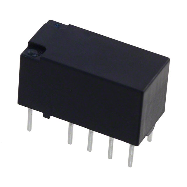
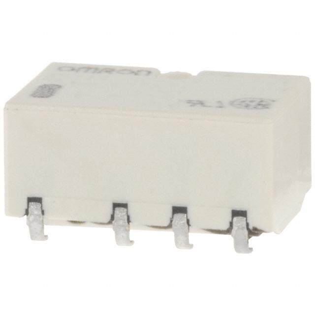
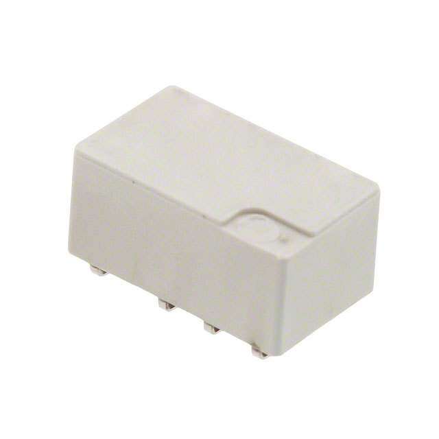
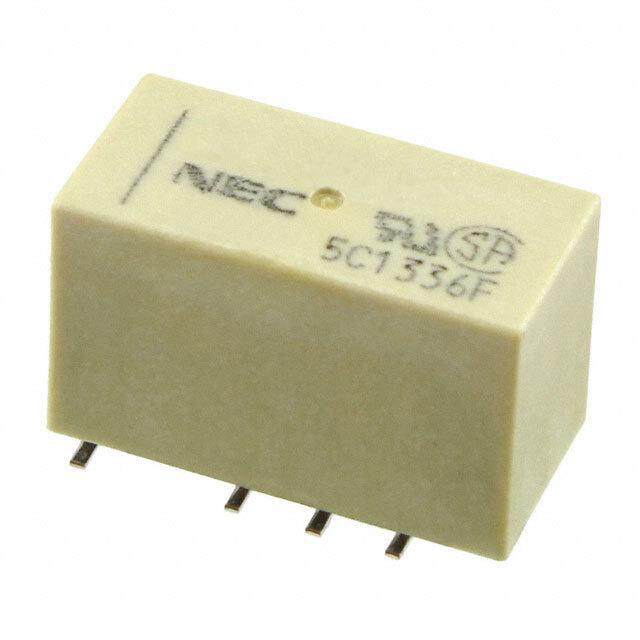
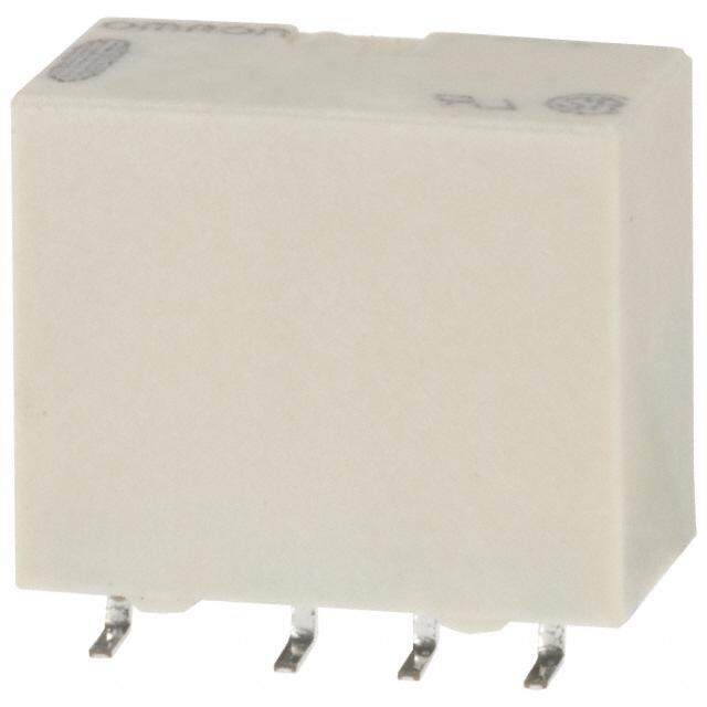
ICGOO电子元器件商城为您提供TX2-L2-5V由Panasonic Corporation设计生产,在icgoo商城现货销售,并且可以通过原厂、代理商等渠道进行代购。 TX2-L2-5V价格参考¥20.40-¥24.23。Panasonic CorporationTX2-L2-5V封装/规格:信号继电器,高达 2 A, Telecom Relay DPDT (2 Form C) Through Hole。您可以下载TX2-L2-5V参考资料、Datasheet数据手册功能说明书,资料中有TX2-L2-5V 详细功能的应用电路图电压和使用方法及教程。
Panasonic Electric Works的TX2-L2-5V是一款额定电流高达2A的信号继电器,广泛应用于需要小信号控制大电流负载的自动化与电子控制系统中。该继电器线圈电压为5V DC,适合低电压控制电路,具有灵敏度高、响应快、寿命长等特点。

典型应用场景包括:工业自动化设备中的PLC(可编程逻辑控制器)输出模块,用于控制指示灯、电磁阀、小型电机等执行元件;家用电器如空调、洗衣机、热水器中的电路控制部分,实现安全隔离与信号切换;通信设备和电源管理系统中,用于信号传输与电路通断控制;此外,在安防系统、智能楼宇控制及测量仪器中也常用于实现低压控制回路与高压工作回路之间的电气隔离。

TX2-L2-5V采用标准PCB安装设计,结构紧凑,适合高密度电路板布局,同时具备良好的耐环境性能,可在较宽温度范围内稳定运行。其密封型设计有效防尘防潮,提升了在复杂工业环境中的可靠性。总体而言,该继电器适用于对稳定性、安全性和空间布局有较高要求的中低功率控制场合。
| 参数 | 数值 |
| 产品目录 | |
| 描述 | RELAY TELECOM DPDT 2A 5V低信号继电器 - PCB 2A 5VDC DPDT 2 COIL LATCH PCB |
| 产品分类 | |
| 品牌 | Panasonic Electric Works |
| 产品手册 | |
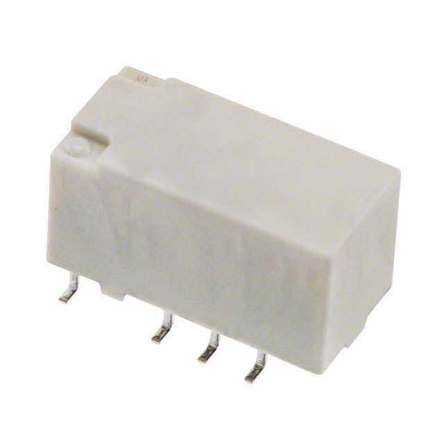
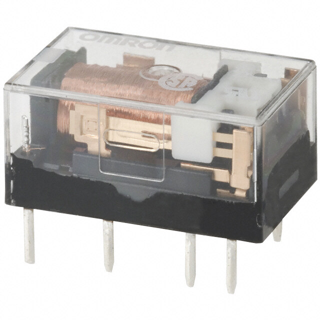
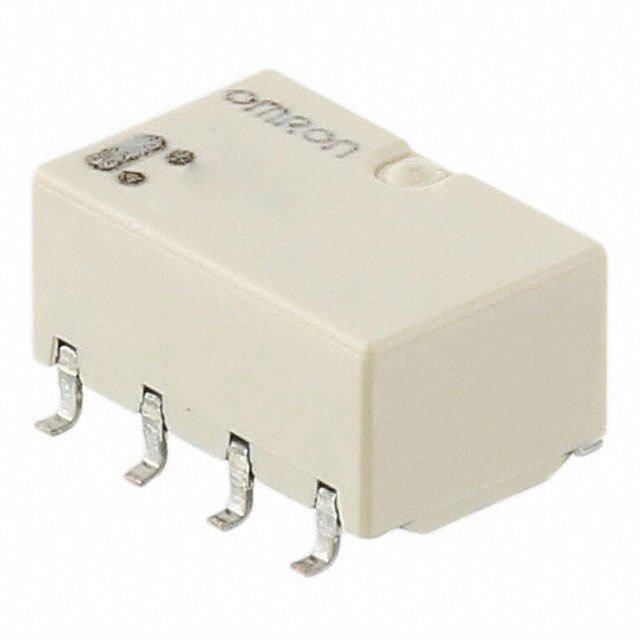
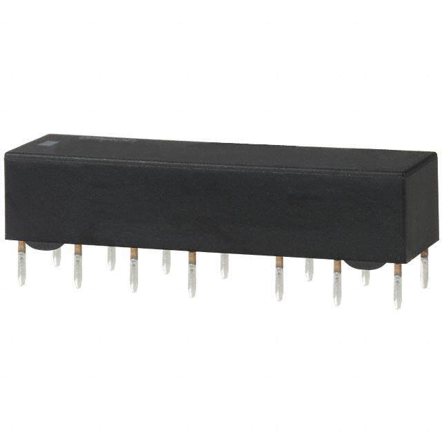
| 产品图片 |
|
| rohs | 符合RoHS无铅 / 符合限制有害物质指令(RoHS)规范要求 |
| 产品系列 | 低信号继电器 - PCB,Panasonic Industrial Devices TX2-L2-5VTX |
| mouser_ship_limit | 该产品可能需要其他文件才能进口到中国。 |
| 数据手册 | |
| 产品型号 | TX2-L2-5V |
| 产品 | Low Profile Relays |
| 产品培训模块 | http://www.digikey.cn/PTM/IndividualPTM.page?site=cn&lang=zhs&ptm=17685 |
| 产品目录绘图 |
|
| 产品目录页面 | |
| 产品种类 | 低信号继电器 - PCB |
| 介入损耗 | 0.8 dB at 1 GHz |
| 关闭电压(最小值) | - |
| 其它名称 | 255-1785 |
| 其它有关文件 | |
| 功耗 | 200 mW |
| 包装 | 管件 |
| 商标 | Panasonic Industrial Devices |
| 安装类型 | 通孔 |
| 安装风格 | Through Hole |
| 导通电压(最大值) | 3.75 VDC |
| 封装 | Tube |
| 工作时间 | 4ms |
| 工作温度 | -40°C ~ 85°C |
| 工厂包装数量 | 40 |
| 开关电压 | 220VDC - 最小值 |
| 最大开关电流 | 2 A |
| 标准包装 | 40 |
| 特性 | 密封式 - 全部 |
| 端子类型 | PC 引脚 |
| 端接类型 | Solder Pin |
| 线圈功率 | 200 mW |
| 线圈电压 | 5VDC |
| 线圈电流 | 40mA |
| 线圈电阻 | 125 欧姆 |
| 线圈类型 | 锁存,双线圈 |
| 绝缘 | 20 dB at 1 GHz |
| 继电器类型 | 电信 |
| 触头外形 | DPDT(2 C 型) |
| 触头材料 | Silver(Ag),Gold(Au) |
| 触点形式 | DPDT (2 Form C) |
| 触点电流额定值 | 2 A |
| 触点额定值 | 2 A at 30 VDC |
| 释放时间 | 4ms |
| 额定接触(电流) | 2A |


- 商务部:美国ITC正式对集成电路等产品启动337调查
- 曝三星4nm工艺存在良率问题 高通将骁龙8 Gen1或转产台积电
- 太阳诱电将投资9.5亿元在常州建新厂生产MLCC 预计2023年完工
- 英特尔发布欧洲新工厂建设计划 深化IDM 2.0 战略
- 台积电先进制程称霸业界 有大客户加持明年业绩稳了
- 达到5530亿美元!SIA预计今年全球半导体销售额将创下新高
- 英特尔拟将自动驾驶子公司Mobileye上市 估值或超500亿美元
- 三星加码芯片和SET,合并消费电子和移动部门,撤换高东真等 CEO
- 三星电子宣布重大人事变动 还合并消费电子和移动部门
- 海关总署:前11个月进口集成电路产品价值2.52万亿元 增长14.8%


PDF Datasheet 数据手册内容提取
Automation Controls Catalog 2, 000 V AC TX RELAYS breakdown voltage, 2 Form C and 2 A relays FEATURES TYPICAL APPLICATIONS 1. 2,000 V breakdown voltage between 1. Communications (xDSL, contact and coil Transmission) 2. Outstanding surge resistance. 2. Measurement 1,500 V 10×160μ sec. (FCC part 68) 3. Security (open contacts) 4. Home appliances, and audio/visual 2,500 V 2×10μ sec. (Telcordia) equipment (contact and coil) 5. Medical equipment 3. Nominal operating power: High sensitivity of 140mW 4. High contact capacity: 2 A 30 V DC 5. Compact size 15.0 (L) × 7.4 (W) × 8.2 (H) mm .591 (L) × .291 (W) × .323 (H) inch 6. High contact reliability High contact reliability is achieved by the use of gold-clad twin crossbar contacts, low-gas formation materials, mold sealing the coil section, and by controlling organic gas in the coil. *We also offer a range of products with AgPd contacts suitable for use in low level load analog circuits ORDERING INFORMATION TX 2 Contact arrangement 2: 2 Form C Surface-mount availability Nil: Standard PC board terminal type SA:SA type SS:SS type Operating function Nil: Single side stable L : 1 coil latching L2: 2 coil latching (SET = 1,6 Pin)*2 LT: 2 coil latching (SET = 1,12 Pin) Terminal shape Nil:Standard PC board terminal or surface-mount terminal Nominal coil voltage (DC)*1 1.5, 3, 4.5, 5, 6, 9, 12, 24, 48V (48V coil type: Single side stable only) Contact material Nil:Standard contact (Ag+Au clad) 1: AgPd contact (low level load); AgPd+Au clad (stationary), AgPd (movable) Packing style Nil:Tube packing X: Tape and reel (picked from 1/3/4/5-pin side) W: Tape and reel packing (picked from the 1/3/4/5-pin side) With humidity indicator and silica gel in moisture proof bag Z: Tape and reel packing (picked from the 8/9/10/12-pin side) Y: Tape and reel packing (picked from the 8/9/10/12-pin side) With humidity indicator and silica gel in moisture proof bag Note 1) In case of 5 V transistor drive circuit, it is recommended to use 4.5 V type relay Note 2) Please contact our sales representative for detailed specifications. 2019.08 industrial.panasonic.com/ac/e/ ー 1 ー ©Panasonic Corporation 2019 ASCTB18E 201908
TX TYPES 1.Standard PC board terminal Contact Nominal coil Single side stable 2 coil latching arrangement voltage Part No. Part No. 3 V DC TX2-3V TX2-LT-3V 4.5 V DC TX2-4.5V TX2-LT-4.5V 5 V DC TX2-5V TX2-LT-5V 2 Form C 6 V DC TX2-6V TX2-LT-6V 9 V DC TX2-9V TX2-LT-9V 12 V DC TX2-12V TX2-LT-12V 24 V DC TX2-24V TX2-LT-24V Standard packing: Tube: 40 pcs.; Case: 1,000 pcs. Note: Please add “-1” to the end of the part number for AgPd contacts (low level load). 2.Surface-mount terminal 1)Tube packing Contact Nominal coil Single side stable 2 coil latching arrangement voltage Part No. Part No. 3 V DC TX2SA-3V TX2SA-LT-3V 4.5 V DC TX2SA-4.5V TX2SA-LT-4.5V 5 V DC TX2SA-5V TX2SA-LT-5V 2 Form C 6 V DC TX2SA-6V TX2SA-LT-6V 9 V DC TX2SA-9V TX2SA-LT-9V 12 V DC TX2SA-12V TX2SA-LT-12V 24 V DC TX2SA-24V TX2SA-LT-24V Standard packing: Tube: 40 pcs.; Case: 1,000 pcs. Note: Please add “-1” to the end of the part number for AgPd contacts (low level load). 2)Tape and reel packing Contact Nominal coil Single side stable 2 coil latching arrangement voltage Part No. Part No. 3 V DC TX2SA-3V-Z TX2SA-LT-3V-Z 4.5 V DC TX2SA-4.5V-Z TX2SA-LT-4.5V-Z 5 V DC TX2SA-5V-Z TX2SA-LT-5V-Z 2 Form C 6 V DC TX2SA-6V-Z TX2SA-LT-6V-Z 9 V DC TX2SA-9V-Z TX2SA-LT-9V-Z 12 V DC TX2SA-12V-Z TX2SA-LT-12V-Z 24 V DC TX2SA-24V-Z TX2SA-LT-24V-Z Standard packing: Tape and reel: 500 pcs.; Case: 1,000 pcs. Notes: 1. Tape and reel packing symbol “-Z” is not marked on the relay. “X” type tape and reel packing (picked from 1/3/4/5-pin side) is also available. 2. Tape and reel packing symbol “-Y” is not marked on the relay. “W” type tape and reel packing (picked from 1/3/4/5-pin side) is also available. 3. Please add “-1” to the end of the part number for AgPd contacts (low level load). RATING 1.Coil data • Operating characteristics such as ‘Operate voltage’ and ‘Release voltage’ are influenced by mounting conditions, ambient temperature, etc. Therefore, please use the relay within ± 5% of rated coil voltage. • ‘Initial’ means the condition of products at the time of delivery. 1)Single side stable Nominal operating Max. applied Nominal coil Pick-up voltage Drop-out voltage Coil resistance Nominal operating current voltage voltage (at 20°C 68°F) (at 20°C 68°F) [±10%] (at 20°C 68°F) power [±10%] (at 20°C 68°F) (at 20°C 68°F) 3 V DC 46.7 mA 64.3 Ω 4.5 V DC 31 mA 145 Ω 5 V DC 75%V or less of 10%V or more of 28.1 mA 178 Ω 150%V of 6 V DC nominal voltage* nominal voltage* 23.3 mA 257 Ω 140 mW nominal voltage 9 V DC (Initial) (Initial) 15.5 mA 579 Ω 12 V DC 11.7 mA 1,028 Ω 24 V DC 5.8 mA 4,114 Ω 2)1 coil latching Nominal operating Coil resistance Nominal operating Max. applied Nominal coil Set voltage Reset voltage current [±10%] (at 20°C 68°F) power voltage voltage (at 20°C 68°F) (at 20°C 68°F) [±10%] (at 20°C 68°F) (at 20°C 68°F) Set coil Reset coil Set coil Reset coil Set coil Reset coil 3 V DC 66.7 mA 66.7 mA 45 Ω 45 Ω 4.5 V DC 44.5 mA 44.5 mA 101.2 Ω 101.2 Ω 5 V DC 75%V or less of 75%V or less of 40 mA 40 mA 125 Ω 125 Ω 150%V of 6 V DC nominal voltage* nominal voltage* 33.3 mA 33.3 mA 180 Ω 180 Ω 200 mW 200 mW nominal voltage 9 V DC (Initial) (Initial) 22.2 mA 22.2 mA 405 Ω 405 Ω 12 V DC 16.7 mA 16.7 mA 720 Ω 720 Ω 24 V DC 8.3 mA 8.3 mA 2,880 Ω 2,880 Ω *Pulse drive (JIS C 5442-1986) Panasonic Corporation Electromechanical Control Business Division industrial.panasonic.com/ac/e/ ー 2 ー ©Panasonic Corporation 2019 ASCTB18E 201908
TX 2.Specifications Characteristics Item Specifications Arrangement 2 Form C Initial contact resistance, max. Max. 100 mΩ (By voltage drop 6 V DC 1A) Contact Standard contact: Ag+Au clad, Contact material AgPd contact (low level load): AgPd+Au clad (stationary), AgPd (movable) Nominal switching capacity Standard contact: 2 A 30 V DC, AgPd contact: 1 A 30 V DC (resistive load) Max. switching power Standard contact: 60 W (DC), AgPd contact: 30 W (DC) (resistive load) Max. switching voltage 220V DC Rating Max. switching current Standard contact: 2 A, AgPd contact: 1 A Min. switching capacity (Reference value)*1 10µA 10mV DC Nominal operating Single side stable 140 mW (3 to 24 V DC) power 2 coil latching 200 mW (3 to 24 V DC) Insulation resistance (Initial) Min. 1,000MΩ (at 500V DC) Measurement at same location as “Initial breakdown voltage” section. Between open contacts 1,000 Vrms for 1min. (Detection current: 10mA) Breakdown voltage Between contact and coil 2,000 Vrms for 1min. (Detection current: 10mA) (Initial) Between contact sets 1,000 Vrms for 1min. (Detection current: 10mA) Surge breakdown Between open contacts 1,500 V (10×160µs) (FCC Part 68) Electrical voltage (Initial) Between contacts and coil 2,500 V (2×10µs) (Telcordia) characteristics Max. 50°C Temperature rise (at 20°C 68°F) (By resistive method, nominal coil voltage applied to the coil; contact carrying current: 2A.) Operate time [Set time] (at 20°C 68°F) Max. 4 ms [Max. 4 ms] (Nominal coil voltage applied to the coil, excluding contact bounce time.) Max. 4 ms [Max. 4 ms] (Nominal coil voltage applied to the coil, excluding contact bounce time.) Release time [Reset time] (at 20°C 68°F) (without diode) Functional Min. 750 m/s2 (Half-wave pulse of sine wave: 6 ms; detection time: 10µs.) Shock resistance Mechanical Destructive Min. 1,000 m/s2 (Half-wave pulse of sine wave: 6 ms.) characteristics Functional 10 to 55 Hz at double amplitude of 3.3 mm (Detection time: 10µs.) Vibration resistance Destructive 10 to 55 Hz at double amplitude of 5 mm Mechanical Min. 108 (at 180 cpm) Expected life Electrical (Standard contact) Min. 105 (2 A 30 V DC resistive), 5×10⁵ (1 A 30 V DC resistive) (at 20 cpm) Ambient temperature: –40°C to +85°C (up to 24 V coil) –40°F to +185°F (up to 24 V coil) Conditions for operation, transport and storage*2 [–40°C to +70°C (48 V coil) –40°F to +158°F (48 V coil)]; Conditions Humidity: 5 to 85% R.H. (Not freezing and condensing at low temperature) Max. operating speed (at rated load) 20 cpm Unit weight Approx. 2 g .071 oz Notes:*1 This value can change due to the switching frequency, environmental conditions, and desired reliability level, therefore it is recommended to check this with the actual load. (AgPd contact type is available for low level load switching [10V DC, 10mA max. level]). *2 Refer to “AMBIENT ENVIRONMENT” in GENERAL APPLICATION GUIDELINES. REFERENCE DATA 1.Maximum switching capacity 2.Life curve 3.Mechanical life Tested sample: TX2-5V, 10 pcs. Operating speed: 180 cpm V100 % 3.0 e, 90 g Switching current, A000012......234500 DC resistive load 4No. of operations ×1010532100000 3re0sVis DtivCe load Ratio against the rated volta 23456780000000 PDircokp-u-opu vt ovlotaltgaege MMMaainxx... 10 Min. 0 0 0 20 30 50 100 200300 1.0 2.0 10 100 1,000 10,000 Contact voltage, V Switching current, A No. of operations, ×104 4.Electrical life (2A 30V DC resistive load) 5.Coil temperature rise Tested sample: TX2-5V, 6 pcs. Tested sample: TX2-5V, 6 pcs. Operating speed: 20 cpm Point measured: Inside the coil Change of pick-up and drop-out voltage Change of contact resistance Ambient temperature: 25°C 77°F, 85°C 185°F %V100 100 70 +25°C+77°F o against the rated voltage, 34567890000000 DPriocpk--uopu tv vooltlataggee MMMaianxx... Contact resistance, mΩ34567890000000 MMainx.. Temperature rise, °C3624500000 +2208AAA5°C+185°F Rati 20 20 0A 10 Min. 10 10 0 0 0 1 2 3 4 5 6 7 8 9 10 1 2 3 4 5 6 7 8 9 10 100 110 120 130 140 150 No. of operations, ×104 No. of operations, ×104 Coil applied voltage, % Panasonic Corporation Electromechanical Control Business Division industrial.panasonic.com/ac/e/ ー 3 ー ©Panasonic Corporation 2019 ASCTB18E 201908
TX 6-(1). Operate and release time (with diode) 6-(2). Operate and release time (without diode) 7. Ambient temperature characteristics Tested sample: TX2-5V, 10 pcs. Tested sample: TX2-5V, 10 pcs. Tested sample: TX2-5V, 5 pcs. 5 5 Operate time Operate time % Operate and release time, ms 243 MMMMaaiinnxx.... Release time Operate and release time, ms243 MMMMaaiinxnx.... Release time –40 –20 0 Rate of change, 2–4202A000m4b0Dvieornoltt6ap t0g-Peoemiuctkp8-e0xxurpa tvuorelta, g°Ce 1 1 –40 0 0 70 80 90 100 110 120 70 80 90 100 110 120 Coil applied voltage, %V Coil applied voltage, %V 8-(1). High frequency characteristics 8-(2). High frequency characteristics 9.Malfunctional shock (single side stable) (Isolation) (Insertion loss) Tested sample: TX2-5V, 6 pcs. Tested sample: TX2-12V, 2 pcs. Tested sample: TX2-12V, 2 pcs. Z' Z XX' Y DEneeerngeizrgeidz ecdo ncdointidointion Y 1000m/s2 Y' B Isolation, dB100 nsertion loss, d 10..08 1000mX/s2 10Z00m/s2 50 I 0.6 1000m/s2 1000m/s2 Z' X' 0.4 1000m/s2 0.2 Y' 10 100 1,000 10 100 1,000 Frequency, MHz Frequency, MHz 10-(1). Influence of adjacent mounting 10-(2). Influence of adjacent mounting Tested sample: TX2-12V, 6 pcs. Tested sample: TX2-12V, 6 pcs. Rate of change, %–505 Pick-up voltage ONONON Rate of change, %–505 Pick-up voltage OONNON Rate of change, %–505 Drop-out voltage OFOFFFOFF Rate of change, %–505 Drop-out voltage OOFFFFOFF 0 2 4 6 8 10 0 2 4 6 8 10 .079.157.236.315.394 .079.157.236.315.394 Inter-relay distance , mminch Inter-relay distance , mminch 11.Pulse dialing test Change of pick-up and drop-out voltage Change of contact resistance Tested sample: TX2-5V, 6 pcs. (35 mA 48 V DC wire spring relay load) 100 100 V 4+–8V DC0μ.0F8445588 ΩΩ0μ.0FW8ire spring relay 43TX o against the rated voltage, % 34567890000000 DPriocpk--ouupt vvoollttaaggee MMMaainxx... Contact resistance, mΩ 34567890000000 MMainx.. ati 20 20 R Min. 10 10 0 0 10 20 30 40 50 10 20 30 40 50 No. of operation, ×104 No. of operations, ×104 Note: Data of surface-mount type are the same as those of PC board terminal type. Panasonic Corporation Electromechanical Control Business Division industrial.panasonic.com/ac/e/ ー 4 ー ©Panasonic Corporation 2019 ASCTB18E 201908
TX DIMENSIONS CAD Data 1. Standard PC board terminal Single side stable type 2 coil latching type CAD Data 15.00 7.40 15.00 7.40 .591 .291 .591 .291 .00.26658.3.2203 .00.2665 8.3.2203 0.50 0.50 1..00.124505 .52.0008 .21.0504 3.1.5308 5.2.0080 0.0.2150 .1.00.412505 .52.0008 .21.0504 3.1.5308 .52.0008 .00.1205 10.16 12.7 2.54 .400 +1 3 4 5 2.54 .500 +1 3 4 5 6+ 1 3 4 5 6 .100 .100 + − + − 5.08 5.08 .200 – .200 – – 12 109 8 7 12 10 9 8 12 10 9 8 7 8-1.0 dia. 10-1.0 dia. 8-.039 dia. Direction indication 10-.039 dia. Direction indication Direction indication Operating function LT Operating function L2 2.Surface-mount terminal CAD Data .51951 8.3.223 .383.14 .279.41 .51951 8.3.223 .383.14 .279.41 .31.2146.0319 5.2.0080 .21.0504 .31.2146.0319 .52.0008 .21.0504 0.25 0.25 0.5 0.0.6256 5.2.0080 .010 0.5 0.0.6256 5.2.0080 .010 7.2.2845 7.2.2845 .020 5.08 2.54 9.4±0.5 .020 5.08 2.54 9.4±0.5 .200 .100 .370±.020 .200 .100 .370±.020 –12 10 9 8 –12 10 9 8 7– 12 109 8 7 + − + − + 1 3 4 5 +1 3 4 5 6+ 1 3 4 5 6 Direction indication Direction indication Direction indication Operating function LT Operating function L2 Panasonic Corporation Electromechanical Control Business Division industrial.panasonic.com/ac/e/ ー 5 ー ©Panasonic Corporation 2019 ASCTB18E 201908
TX NOTES 1.Packing style 2.Automatic insertion 1)The relay is packed in a tube with the To maintain the internal function of the relay orientation mark on the left side, as relay, the chucking pressure should not shown in the figure below. exceed the values below. Chucking pressure in the direction A: 4.9 N {500gf} or less Orientation (indicates PIN No.1) stripe Chucking pressure in the direction B: 9.8 N {1 kgf} or less Chucking pressure in the direction C: 9.8 N {1 kgf} or less Stopper (gray) Stopper (green) C B A 2)Tape and reel packing (Surface-mount terminal type) (1)Tape dimensions mm inch R(Ze tlyapy ep)olarity bar.015.95+ + 00.00.014ddiiaa...027.09 .145.07 1.0.7659 .001.46 PAvleoaids ec hcuhcukcikn gth teh e c e n pteorr toiof nth.e relay. C In addition, excessive chucking pressure A B 11.5 .453 15.5 to the pinpoint of the relay should be .610 Relays 1.663.00 10.0.D394 .2944.50±±0.0.312 9.2±0.2 avoided. .362±.008 Tape coming out direction (2)Dimensions of plastic reel mm inch 2.0 .079 380 dia. 13 dia. 21 dia. 14.961 dia. .512 dia. .827 dia. 80 dia. 3.150 dia. Ambient Environment Usage, Transport, and Storage Conditions During usage, storage, or transportation, avoid locations subjected to direct sunlight and maintain normal temperature, humidity and pressure conditions. Temperature/Humidity When transporting or storing relays while they are tube packaged, there are cases the temperature may differ from the allowable range. In this case be sure to check the individual specifications. Also allowable humidity level is influenced by temperature, please check charts shown below and use relays within mentioned conditions. (Allowable temperature values) Humidity (%RH) 85 Allowable range Avoid icing Avoid con- Please refer to "the latest product specifications" when used at densation when when designing your product. temperatures used at tem- lower than 0°C peratures higher •Requests to customers : than 0°C https://industrial.panasonic.com/ac/e/salespolicies/ 5 -40 0 85 Temperature(°C) Panasonic Corporation Electromechanical Control Business Division industrial.panasonic.com/ac/e/ ー 6 ー ©Panasonic Corporation 2019 ASCTB18E 201908
GUIDELINES FOR SIGNAL RELAYS USAGE For cautions for use, please read “GUIDELINES FOR RELAY USAGE”. https://industrial.panasonic.com/ac/e/control/relay/cautions_use/index.jsp Precautions for Coil Input Long term current carrying Temperature rise due to pulse voltage A circuit that will be carrying a current continuously for long periods When a pulse voltage with ON time of less than 2 minutes is used, the without relay switching operation. (circuits for emergency lamps, alarm coil temperature rise bares no relationship to the ON time. This varies devices and error inspection that, for example, revert only during with the ratio of ON time to OFF time, and compared with continuous malfunction and output warnings with form B contacts) Continuous, current passage, it is rather small. The various relays are essentially long-term current to the coil will facilitate deterioration of coil insulation the same in this respect. and characteristics due to heating of the coil itself. Current passage time (%) For circuits such as these, please use a magnetic-hold type latching For continuousu passage Tempereture rise value is 100% relay. If you need to use a single stable relay, use a sealed type relay ON : OFF = 3 : 1 About 80% that is not easily affected by ambient conditions and make a failsafe ON : OFF = 1 : 1 About 50% circuit design that considers the possibility of contact failure or disconnection. ON : OFF = 1 : 3 About 35% DC Coil operating power Steady state DC current should be applied to the coil. The wave form ON : OFF = 1 : 1 e should be rectangular. If it includes ripple, the ripple factor should be g a less than 5%. olt V However, please check with the actual circuit since the electrical characteristics may vary. The rated coil voltage should be applied to the coil and the set/reset pulse time of latching type relay differs for Time each relays, please refer to the relay's individual specifications. Coil connection Operate voltage change due to coil temperature rise When connecting coils of polarized relays, please check coil polarity (Hot start) (+,-) at the internal connection diagram (Schematic). If any wrong In DC relays, after continuous passage of current in the coil, if the connection is made, it may cause unexpected malfunction, like current is turned OFF, then immediately turned ON again, due to the abnormal heat, fire and so on, and circuit do not work. Avoid temperature rise in the coil, the pick-up voltage will become somewhat impressing voltages to the set coil and reset coil at the same time. higher. Also, it will be the same as using it in a higher temperature Maximum allowable voltage and temperature rise atmosphere. The resistance/temperature relationship for copper wire Proper usage requires that the rated coil voltage be impressed on the is about 0.4% for 1°C, and with this ratio the coil resistance increases. coil. Note, however, that if a voltage greater than or equal to the That is, in order to operate of the relay, it is necessary that the voltage maximum continuous voltage is impressed on the coil, the coil may be higher than the pick-up voltage and the pick-up voltage rises in burn or its layers short due to the temperature rise. Furthermore, do accordance with the increase in the resistance value. However, for not exceed the usable ambient temperature range listed in the catalog. some polarized relays, this rate of change is considerably smaller. Maximum allowable voltage for coil In addition to being a requirement for relay operation stability, the maximum continuous impressed coil voltage is an important constraint for the prevention of such problems as thermal deterioration or deformity of the insulation material, or the occurrence of fire hazards. Panasonic Corporation Electromechanical Control Business Division industrial.panasonic.com/ac/e/ ー 7 ー c Panasonic Corporation 2019 ASCTB414E 201906
GUIDELINES FOR SIGNAL RELAYS USAGE Ambient Environment Dew condensation 2) If relays will not be used within 72 hours, please store relays in a Condensation occurs when the ambient temperature drops suddenly humidity controlled desiccator or in an anti-humidity bag to which from a high temperature and humidity, or the relay and microwave silica gel has been added. device is suddenly transferred from a low ambient temperature to a * If the relay is to be soldered after it has been exposed to excessive high temperature and humidity. Condensation causes the failures like humidity atmosphere, cracks and leaks can occur. Be sure to mount insulation deterioration, wire disconnection and rust etc. the relay under the required mounting conditions Panasonic Corporation does not guarantee the failures caused by 3) The following cautionary label is affixed to the anti-humidity pack. condensation. The heat conduction by the equipment may accelerate the cooling of device itself, and the condensation may occur. Please conduct product evaluations in the worst condition of the actual usage. (Special attention should be paid when high temperature heating parts are close to the device. Also please consider the condensation may occur inside of the device.) Icing Condensation or other moisture may freeze on relays when the temperature become lower than 0°C.This icing causes the sticking of movable portion, the operation delay and the contact conduction failure etc. Panasonic Corporation does not guarantee the failures caused by the icing. The heat conduction by the equipment may accelerate the cooling of relay itself and the icing may occur. Please conduct product Silicon evaluations in the worst condition of the actual usage. When a source of silicone substances (silicone rubber, silicone oil, Low temperature and low humidity silicone coating materials and silicone filling materials etc.) is used The plastic becomes brittle if the switch is exposed to a low around the relay, the silicone gas (low molecular siloxane etc.) may be temperature, low humidity environment for long periods of time. produced. High temperature and high humidity This silicone gas may penetrate into the inside of the relay. When the Storage for extended periods of time (including transportation periods) relay is kept and used in this condition, silicone compound may adhere at high temperature or high humidity levels or in atmospheres with to the relay contacts which may cause the contact failure. Do not use organic gases or sulfide gases may cause a sulfide film or oxide film to any sources of silicone gas around the relay (Including plastic seal form on the surfaces of the contacts and/or it may interfere with the types). functions. Check out the atmosphere in which the units are to be NOx Generation stored and transported. When relay is used in an atmosphere high in humidity to switch a load Package which easily produces an arc, the NOx created by the arc and the In terms of the packing format used, make every effort to keep the water absorbed from outside the relay combine to produce nitric acid. effects of moisture, organic gases and sulfide gases to the absolute This corrodes the internal metal parts and adversely affects operation. minimum. Avoid use at an ambient humidity of 85% RH or higher (at 20°C). If use Storage requirements at high humidity is unavoidable, please contact our sales Since the SMD type is sensitive to humidity it is packaged with tightly representative. sealed anti-humidity packaging. However, when storing, please be careful of the following. 1) Please use promptly once the anti-humidity pack is opened.(Signal relay: within 72 hours, Max. 30°C/70% RH). If left with the pack open, the relay will absorb moisture which will cause thermal stress when reflow mounting and thus cause the case to expand. As a result, the seal may break. Others Cleaning 1) Although the environmentally sealed type relay (plastic sealed type, 3) Cleaning with the boiling method is recommended (The temperature etc.) can be cleaned, avoid immersing the relay into cold liquid (such of cleaning liquid should be 40°C or lower). as cleaning solvent) immediately after soldering. Doing so may Avoid ultrasonic cleaning on relays. Use of ultrasonic cleaning may deteriorate the sealing performance. cause breaks in the coil or slight sticking of the contacts due to the 2) Surface mount terminal type relay is sealed type and it can be ultrasonic energy. cleaned by immersion. Use pure water or alcohol-based cleaning solvent. Please refer to "the latest product specifications" when designing your product. •Requests to customers: https://industrial.panasonic.com/ac/e/salespolicies/ Panasonic Corporation Electromechanical Control Business Division industrial.panasonic.com/ac/e/ ー 8 ー c Panasonic Corporation 2019 ASCTB414E 201906
Please contact .......... Electromechanical Control Business Division 1006, Oaza Kadoma, Kadoma-shi, Osaka 571-8506, Japan industral.panasonic.com/ac/e/ ©Panasonic Corporation 2019 ASCTB18E 201908 Specifications are subject to change without notice.