ICGOO在线商城 > 集成电路(IC) > 线性 - 放大器 - 仪表,运算放大器,缓冲器放大器 > TSH73CPT
 Datasheet下载
- 型号: TSH73CPT
- 制造商: STMicroelectronics
- 库位|库存: xxxx|xxxx
- 要求:
| 数量阶梯 | 香港交货 | 国内含税 |
| +xxxx | $xxxx | ¥xxxx |
查看当月历史价格
查看今年历史价格
TSH73CPT产品简介:
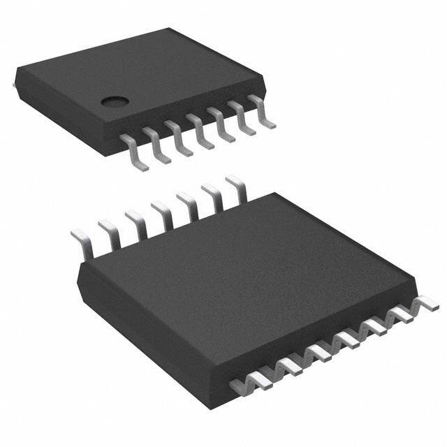
ICGOO电子元器件商城为您提供TSH73CPT由STMicroelectronics设计生产,在icgoo商城现货销售,并且可以通过原厂、代理商等渠道进行代购。 TSH73CPT价格参考。STMicroelectronicsTSH73CPT封装/规格:线性 - 放大器 - 仪表,运算放大器,缓冲器放大器, 通用 放大器 3 电路 满摆幅 14-TSSOP。您可以下载TSH73CPT参考资料、Datasheet数据手册功能说明书,资料中有TSH73CPT 详细功能的应用电路图电压和使用方法及教程。
STMicroelectronics的TSH73CPT是一款高性能的仪表放大器,属于线性放大器类别,广泛应用于需要高精度信号处理的场景。以下是其主要应用场景:

1. 工业自动化与控制:
   TSH73CPT适用于工业传感器信号调理,例如压力、温度、位移等传感器输出信号的放大和处理。其高共模抑制比(CMRR)和低噪声特性使其在复杂电磁环境下表现优异,适合用于工业自动化控制系统。

2. 医疗设备:
   在医疗领域,该芯片可用于心电图(ECG)、脑电图(EEG)和其他生物电信号采集系统中。其低功耗和高精度特性确保了对微弱生理信号的准确放大,同时减少了对患者的干扰。

3. 精密测量仪器:
   该器件适用于需要高精度测量的应用,如数据采集系统、测试设备和实验室仪器。其出色的线性和稳定性使得它成为精密测量的理想选择。

4. 汽车电子:
   TSH73CPT可应用于汽车传感器信号处理,如轮胎压力监测系统(TPMS)、发动机管理系统的传感器接口等。其宽工作温度范围和可靠性满足汽车环境的严格要求。

5. 消费电子:
   在高端音频设备中,TSH73CPT可用作前置放大器,提供低失真和高保真的信号放大功能。此外,它也可用于家用健康监测设备,如智能秤或血氧仪。

6. 航空航天与国防:
   由于其卓越的性能和可靠性,TSH73CPT还可用于航空航天和国防领域的信号处理任务,如导航系统、遥感设备和通信设备中的信号放大。

总之,TSH73CPT凭借其高精度、低噪声、低功耗和高稳定性的特点,适用于各种需要精确信号放大的应用场合,特别是在对噪声敏感或需要高共模抑制的环境中表现出色。
| 参数 | 数值 |
| -3db带宽 | 100MHz |
| 产品目录 | 集成电路 (IC) |
| 描述 | IC OPAMP GP 65MHZ RRO 14TSSOP |
| 产品分类 | Linear - Amplifiers - Instrumentation, OP Amps, Buffer Amps |
| 品牌 | STMicroelectronics |
| 数据手册 | |
| 产品图片 |
|
| 产品型号 | TSH73CPT |
| rohs | 无铅 / 符合限制有害物质指令(RoHS)规范要求 |
| 产品系列 | - |
| 产品目录页面 | |
| 供应商器件封装 | 14-TSSOP |
| 其它名称 | 497-8156-2 |
| 其它有关文件 | http://www.st.com/web/catalog/sense_power/FM123/SC61/SS1612/PF65503?referrer=70071840 |
| 包装 | 带卷 (TR) |
| 压摆率 | 118 V/µs |
| 增益带宽积 | 65MHz |
| 安装类型 | 表面贴装 |
| 封装/外壳 | 14-TSSOP(0.173",4.40mm 宽) |
| 工作温度 | 0°C ~ 70°C |
| 放大器类型 | 通用 |
| 标准包装 | 2,500 |
| 电压-电源,单/双 (±) | 3 V ~ 12 V, ±1.5 V ~ 6 V |
| 电压-输入失调 | 800µV |
| 电流-电源 | 9.8mA |
| 电流-输入偏置 | 6µA |
| 电流-输出/通道 | 55mA |
| 电路数 | 3 |
| 输出类型 | 满摆幅 |


- 商务部:美国ITC正式对集成电路等产品启动337调查
- 曝三星4nm工艺存在良率问题 高通将骁龙8 Gen1或转产台积电
- 太阳诱电将投资9.5亿元在常州建新厂生产MLCC 预计2023年完工
- 英特尔发布欧洲新工厂建设计划 深化IDM 2.0 战略
- 台积电先进制程称霸业界 有大客户加持明年业绩稳了
- 达到5530亿美元!SIA预计今年全球半导体销售额将创下新高
- 英特尔拟将自动驾驶子公司Mobileye上市 估值或超500亿美元
- 三星加码芯片和SET,合并消费电子和移动部门,撤换高东真等 CEO
- 三星电子宣布重大人事变动 还合并消费电子和移动部门
- 海关总署:前11个月进口集成电路产品价值2.52万亿元 增长14.8%


PDF Datasheet 数据手册内容提取
TSH70, TSH71, TSH72, TSH73, TSH74, TSH75 Rail-to-rail, wide-band, low-power operational amplifiers Datasheet - production data Features TTSSHH7700 :: SSOOTT2233--55//SSOO88 • 3 V, 5 V, ±5 V specifications OOuuttppuutt 11 55 VVCCCC ++ NNCC11 88 NNCC • 3 dB bandwidth: 90 MHz VVCCCC --22 ++ -- IInnvv.. IInn..22 __ 77VVCCCC ++ NNoonn--IInnvv.. IInn..33 44IInnvv.. IInn.. NNoonn--IInnvv.. IInn..33 ++ 66OOuuttppuutt • Gain bandwidth product: 70 MHz VVCCCC --44 55NNCC • Slew rate: 100 V/µs (typical for 5 V) TTSSHH7711 :: SSOO88//TTSSSSOOPP88 • Output current: up to 55 mA NNCC11 88SSTTAANNDDBBYY • Input single supply voltage IInnvveerrttiinngg IInnppuutt 22 __ 77 VVCCCC ++ NNoonn IInnvveerrttiinngg IInnppuutt 33 ++ 66OOuuttppuutt • Output rail-to-rail VVCCCC --44 55NNCC • Specified for 150 Ω loads TTSSHH7722 :: SSOO88//TTSSSSOOPP88 • Low distortion, THD: 0.1 % OOuuttppuutt11 11 88 VVCCCC ++ • SOT23-5, TSSOP, and SO packages IInnvveerrttiinngg IInnppuutt11 22 __ 77 OOuuttppuutt22 NNoonn IInnvveerrttiinngg IInnppuutt11 33 ++ __ 66 IInnvveerrttiinngg IInnppuutt22 VVCCCC -- 44 ++ 55 NNoonn IInnvveerrttiinngg IInnppuutt22 Applications TTSSHH7733 :: SSOO1144//TTSSSSOOPP1144 • Video buffers SSTTAANNDDBBYY11 11 1144OOuuttppuutt33 • ADC driver SSTTAANNDDBBYY22 22 __ 1133IInnvveerrttiinngg IInnppuutt33 SSTTAANNDDBBYY33 33 ++ 1122NNoonn IInnvveerrttiinngg IInnppuutt33 • Hi-fi applications VVCCCC ++ 44 1111VVCCCC -- NNoonn IInnvveerrttiinngg IInnppuutt11 55 ++ ++ 1100NNoonn IInnvveerrttiinngg IInnppuutt22 IInnvveerrttiinngg IInnppuutt11 66 __ __ 99 IInnvveerrttiinngg IInnppuutt22 Description OOuuttppuutt11 77 88 OOuuttppuutt22 The TSH7x series offers single, dual, triple, and TTSSHH7744 :: SSOO1144//TTSSSSOOPP1144 quad operational amplifiers featuring high video OOuuttppuutt11 11 1144OOuuttppuutt44 performances with large bandwidth, low IInnvveerrttiinngg IInnppuutt11 22 __ __ 1133IInnvveerrttiinngg IInnppuutt44 distortion, and excellent supply voltage rejection. NNoonn IInnvveerrttiinngg IInnppuutt11 33 ++ ++ 1122NNoonn IInnvveerrttiinngg IInnppuutt44 Running with a single supply voltage from 3 V to VVCCCC ++ 44 1111VVCCCC -- 12 V, these amplifiers feature a large output NNoonn IInnvveerrttiinngg IInnppuutt22 55 ++ ++ 1100NNoonn IInnvveerrttiinngg IInnppuutt33 IInnvveerrttiinngg IInnppuutt22 66 __ __ 99 IInnvveerrttiinngg IInnppuutt33 voltage swing and high output current capable of OOuuttppuutt22 77 88 OOuuttppuutt33 driving standard 150 Ω loads. A low operating voltage makes TSH7x amplifiers ideal for use in TTSSHH7755 :: SSOO1166//TTSSSSOOPP1166 portable equipment. The TSH71, TSH73, and OOuuttppuutt11 11 1166OOuuttppuutt44 TSH75 also feature standby inputs, each of which IInnvveerrttiinngg IInnppuutt11 22 __ __ 1155IInnvveerrttiinngg IInnppuutt44 allows the op-amp to be put into a standby mode NNoonn IInnvveerrttiinngg IInnppuutt11 33 ++ ++ 1144NNoonn IInnvveerrttiinngg IInnppuutt44 with low-power consumption and high-output VVCCCC ++ 44 1133VVCCCC -- impedance. This function allows power saving or NNoonn IInnvveerrttiinngg IInnppuutt22 55 ++ ++ 1122NNoonn IInnvveerrttiinngg IInnppuutt33 IInnvveerrttiinngg IInnppuutt22 66 __ __ 1111IInnvveerrttiinngg IInnppuutt33 signal switching/multiplexing for high-speed OOuuttppuutt22 77 1100OOuuttppuutt33 applications and video applications. To SSTTAANNDDBBYY 88 99 SSTTAANNDDBBYY economize both board space and weight, the TSH7x series is proposed in SOT23-5, SO, and TSSOP packages. December 2013 DocID7502 Rev 4 1/36 This is information on a product in full production. www.st.com
Contents TSH7x Contents 1 Typical application: video driver . . . . . . . . . . . . . . . . . . . . . . . . . . . . . . . 3 2 Absolute maximum ratings and operating conditions . . . . . . . . . . . . . 4 3 Electrical characteristics . . . . . . . . . . . . . . . . . . . . . . . . . . . . . . . . . . . . 5 3.1 Standby mode . . . . . . . . . . . . . . . . . . . . . . . . . . . . . . . . . . . . . . . . . . . . . .11 3.2 Characteristic curves for V = 3 V . . . . . . . . . . . . . . . . . . . . . . . . . . . . . 12 CC 3.3 Characteristic curves for V = 5 V . . . . . . . . . . . . . . . . . . . . . . . . . . . . . 15 CC 3.4 Characteristic curves for V = 10 V . . . . . . . . . . . . . . . . . . . . . . . . . . . . 18 CC 4 Testing conditions . . . . . . . . . . . . . . . . . . . . . . . . . . . . . . . . . . . . . . . . . . 21 4.1 Layout precautions . . . . . . . . . . . . . . . . . . . . . . . . . . . . . . . . . . . . . . . . . . 21 4.2 Maximum input level . . . . . . . . . . . . . . . . . . . . . . . . . . . . . . . . . . . . . . . . . 22 4.3 Video capabilities . . . . . . . . . . . . . . . . . . . . . . . . . . . . . . . . . . . . . . . . . . . 22 4.4 Precautions when operating on an asymmetrical supply . . . . . . . . . . . . . 24 5 Package information . . . . . . . . . . . . . . . . . . . . . . . . . . . . . . . . . . . . . . . . 26 5.1 SOT23-5 package information . . . . . . . . . . . . . . . . . . . . . . . . . . . . . . . . . 27 5.2 SO8 package information . . . . . . . . . . . . . . . . . . . . . . . . . . . . . . . . . . . . . 28 5.3 TSSOP8 package information . . . . . . . . . . . . . . . . . . . . . . . . . . . . . . . . . 29 5.4 SO14 package information . . . . . . . . . . . . . . . . . . . . . . . . . . . . . . . . . . . . 30 5.5 TSSOP14 package information . . . . . . . . . . . . . . . . . . . . . . . . . . . . . . . . 31 5.6 SO16 package information . . . . . . . . . . . . . . . . . . . . . . . . . . . . . . . . . . . . 32 5.7 TSSOP16 package information . . . . . . . . . . . . . . . . . . . . . . . . . . . . . . . . 33 6 Order information . . . . . . . . . . . . . . . . . . . . . . . . . . . . . . . . . . . . . . . . . . 34 7 Revision history . . . . . . . . . . . . . . . . . . . . . . . . . . . . . . . . . . . . . . . . . . . 35 2/36 DocID7502 Rev 4
TSH7x Typical application: video driver 1 Typical application: video driver A typical application for the TSH7x family is that of a video driver for driving STi7xxx DAC outputs on 75-ohm lines. Figure 1 show the benefits of the TSH7x family as single supply drivers. Figure 1. Benefits of TSH7x family: +3 V or +5 V single supply solution +5V Video DAC’soutputs: Bottom of VOH=4.2Vmin. +3V synchronization tip (Tested) Vcc=+5V VOH=2.45Vmin. around 50mV Vcc=+3V (Tested) 2.1V 2.1V 1Vp-p + 2Vp-p 2Vp-p GND _Gain=2 50mV VOL=40mVmax. VOL=30mVmax. GND (Tested) GND (Tested) GND 100mV 100mV 1kΩ 1kΩ -5V GND +5V Y,G Reconstruction Filtering VDiAdCeo LPF __++ 75Ω 75ΩCable 11VVpppp TV 75Ω 2Vpp Pb,BReconstruction Filtering VDiAdCeo LPF __++ 75Ω 75ΩCable 00..77VVpppp 75Ω 11..44VVpppp Pr,R Reconstruction Filtering VDiAdCeo LPF ++ 75Ω 75ΩCable 00..77VVpppp __ 75Ω 11..44VVpppp TSH73 GND DocID7502 Rev 4 3/36 36
Absolute maximum ratings and operating conditions TSH7x 2 Absolute maximum ratings and operating conditions Table 1. Absolute maximum ratings (AMR) Symbol Parameter Value Unit V Supply Voltage (1) 14 CC V Differential Input Voltage (2) ±2 V id V Input Voltage (3) ±6 i T Operating Free Air Temperature Range 0 to +70 oper T Storage Temperature -65 to +150 °C stg T Maximum Junction Temperature 150 j Thermal resistance junction to case (4) SOT23-5 80 SO8 28 TSSOPO8 37 R thjc SO14 22 TSSOP14 32 SO16 35 TSSOP16 35 °C/W Thermal resistance junction to ambient area SOT23-5 250 SO8 157 TSSOPO8 130 R thja SO14 125 TSSOP14 110 SO16 110 TSSOP16 110 ESD Human body model 2 kV 1. All voltages values, except differential voltage are with respect to the network ground terminal 2. Differential voltages are the non-inverting input terminal with respect to the inverting terminal 3. The magnitude of the input and output must never exceed V +0.3V CC 4. Short-circuits can cause excessive heating Table 2. Operating conditions Symbol Parameter Value Unit V Supply voltage 3 to 12 CC V Common mode input voltage range V - to (V + -1.1) V IC CC CC Standby (V -) to (V +) CC CC 4/36 DocID7502 Rev 4
TSH7x Electrical characteristics 3 Electrical characteristics Table 3. V + = 3 V, V - = GND, V = 1.5 V, T = 25 °C (unless otherwise specified) CC CC IC amb Symbol Parameter Test conditions Min. Typ. Max. Unit T = 25 °C 1.2 10 |V | Input offset voltage amb mV io T < T < T 12 min. amb max. ΔV Input offset voltage drift vs. temp. T < T < T 4 μV/°C io min. amb max. T = 25 °C 0.1 3.5 I Input offset current amb io T < T < T 5 min. amb max. μA T = 25 °C 6 15 I Input bias current amb ib T < T < T 20 min. amb max. C Input capacitance 0.2 pF in T = 25 °C 7.2 9.8 I Supply current per operator amb mA CC T < T < T 11 min. amb max. +0.1 < V <+1.9 V and V = 1.5 V Common mode rejection ratio IC out CMRR (δV /δVio) Tamb = 25 °C 65 90 IC T < T < T 64 min. amb max. Supply voltage rejection ratio T = 25 °C 66 74 SVRR amb (δVCC/δVio) T < T < T 65 min. amb max. dB Power supply rejection ratio PSRR Positive and negative rail 75 (δVCC/δV ) out R = 150 Ω to 1.5 V, V = 1 V to 2 V L out Avd Large signal voltage gain Tamb = 25 °C 70 81 T < T < T 65 min. amb max. T =25 °C, amb V = +1, V to 1.5 V, id out V = -1, V to 1.5 V id out |Source 30 43 I Output short circuit current source |Sink 20 33 mA o Tmin. < Tamb < Tmax. V = +1, V to 1.5 V id out V = -1, V to 1.5 V id out |Source 22 | 19 Sink T = 25 °C amb RL = 150 Ω to GND 2.45 2.60 RL = 600 Ω to GND 2.87 RL = 2 kΩ to GND 2.91 RL = 10 kΩ to GND 2.93 VOH High level output voltage RRLL == 165000 ΩΩ ttoo 11..55 VV 2.65 22..7970 V RL = 2 kΩ to 1.5 V 2.92 RL = 10 kΩ to 1.5 V 2.93 T < T < T min. amb max. R = 150 Ω to GND 2.4 L R = 150 Ω to 1.5V 2.6 L DocID7502 Rev 4 5/36 36
Electrical characteristics TSH7x Table 3. V + = 3 V, V - = GND, V = 1.5 V, T = 25 °C (unless otherwise specified) (continued) CC CC IC amb Symbol Parameter Test conditions Min. Typ. Max. Unit T = 25 °C amb R = 150 Ω to GND 10 30 L R = 600 Ω to GND 11 L R = 2 kΩ to GND 11 L R = 10 kΩ to GND 11 L R = 150 Ω to 1.5 V 140 300 VOL Low level output voltage RL = 600 Ω to 1.5 V 90 mV L R = 2 kΩ to 1.5 V 68 L R = 10 kΩ to 1.5 V 57 L T < T < T min. amb max. R = 150 Ω to GND 40 L R = 150 Ω to 1.5 V 350 L F = 10 MHz GBP Gain bandwidth product A = +11 65 VCL MHz A = -10 55 VCL Bw Bandwidth @-3dB A =+1, R =150 Ω to 1.5 V 87 VCL L A =+2, R =150 Ω // C to 1.5 V VCL L L SR Slew rate C = 5 pF 80 V/μs L C = 30 pF 45 85 L φm Phase margin R =150 Ω // 30 pF to 1.5 V 40 ° L en Equivalent input noise voltage F=100 kHz 11 nV/√Hz A = +2, F = 4 MHz, R =150 Ω // VCL L 30pF to 1.5 V THD Total harmonic distortion dB V = 1 Vpp -61 out V = 2 Vpp -54 out A = +2, V = 2 Vpp VCL out Second order intermodulation R = 150 Ω to 1.5 V IM2 L -76 product Fin1 = 180 kHz, Fin2 = 280 kHz spurious measurements @100 kHz dBc A = +2, V = 2 Vpp VCL out R = 150 Ω to 1.5 V IM3 Third order inter modulation product L -68 Fin1 = 180kHz, Fin2 = 280 kHz spurious measurements @400 kHz A =+2, R = 150 Ω to 1.5 V ΔG Differential gain VCL L 0.5 % F = 4.5 MHz, V = 2 Vpp out A = +2, R = 150 Ω to 1.5 V Df Differential phase VCL L 0.5 ° F = 4.5 MHz, V = 2 Vpp out Gf Gain flatness F = DC to 6 MHz, A = +2 0.2 VCL dB Vo1/Vo2 Channel separation F = 1 MHz to 10 MHz 65 6/36 DocID7502 Rev 4
TSH7x Electrical characteristics Table 4. V + = 5 V, V - = GND, V = 2.5 V, T = 25 °C (unless otherwise specified) CC CC IC amb Symbol Parameter Test conditions Min. Typ. Max. Unit T = 25 °C 1.1 10 |V | Input offset voltage amb mV io T < T < T 12 min. amb max. ΔV Input offset voltage drift vs. temp. T < T < T 3 μV/°C io min. amb max. T = 25 °C 0.1 3.5 I Input offset current amb io T < T < T 5 min. amb max. μA T = 25 °C 6 15 I Input bias current amb ib T < T < T 20 min. amb max. C Input capacitance 0.3 pF in T = 25 °C 8.2 10.5 I Supply current per operator amb mA CC T < T < T 11.5 min. amb max. +0.1 < V < 3.9 V and V = 2.5 V Common mode rejection ratio IC out CMRR (δV /δVio) Tamb = 25 °C 72 97 IC T < T < T 71 min. amb max. Supply voltage rejection ratio T = 25°C 68 75 SVRR amb (δV /δVio) T < T < T 67 CC min. amb max. Power supply rejection ratio dB PSRR Positive and negative rail 75 (δV /δV ) CC out R = 150 Ω to 1.5 V, L V = 1 V to 4 V A Large signal voltage gain out vd T = 25 °C 75 84 amb T < T < T 70 min. amb max. T = 25 °C, amb V = +1, V to 1.5 V, id out V = -1, V to 1.5 V id out |Source 35 55 I Output short circuit current source |Sink 33 55 mA o Tmin. < Tamb < Tmax. V = +1, V to 1.5 V id out V = -1, V to 1.5 V id out |Source 34 | 32 Sink T = 25 °C amb R = 150 Ω to GND 4.2 4.36 L R = 600 Ω to GND 4.85 L R = 2 kΩ to GND 4.90 L R = 10 kΩ to GND 4.93 L R = 150 Ω to 2.5 V 4.5 4.66 VOH High level output voltage RL = 600 Ω to 2.5 V 4.90 V L R = 2 kΩ to 2.5 V 4.92 L R = 10 kΩ to 2.5 V 4.93 L T < T < T min. amb max. R = 150 Ω to GND 4.1 L R = 150 Ω to 2.5 V 4.4 L DocID7502 Rev 4 7/36 36
Electrical characteristics TSH7x Table 4. V + = 5 V, V - = GND, V = 2.5 V, T = 25 °C (unless otherwise specified) (continued) CC CC IC amb Symbol Parameter Test conditions Min. Typ. Max. Unit T =25 °C amb R = 150 Ω to GND 20 40 L R = 600 Ω to GND 23 L R = 2 kΩ to GND 23 L R = 10 kΩ to GND 23 L R = 150 Ω to 2.5 V 220 400 VOL Low level output voltage RL = 600 Ω to 2.5 V 105 mV L R = 2 kΩ to 2.5 V 76 L R = 10 kΩ to 2.5 V 61 L T < T < T min. amb max. R = 150 Ω to GND 60 L R = 150 Ω to 2.5 V 450 L F = 10 MHz GBP Gain bandwidth product A = +11 65 VCL MHz A = -10 55 VCL Bw Bandwidth @-3 dB A = +1, R = 150 Ω to 2.5 V 87 VCL L A = +2, VCL R = 150Ω // C to 2.5 V SR Slew rate L L V/μs C = 5 pF 104 L C = 30 pF 60 105 L φm Phase margin R = 150 Ω // 30 pF to 2.5 V 40 ° L en Equivalent input noise voltage F = 100 kHz 11 nV/√Hz A = +2, F = 4 MHz VCL R = 150 Ω // 30 pF to 2.5 V THD Total harmonic distortion L dB V = 1 Vpp -61 out V = 2 Vpp -54 out A = +2, V = 2Vpp VCL out Second order intermodulation R = 150 Ω to 2.5 V IM2 L -76 product Fin1 = 180 kHz, Fin2 = 280 kHz spurious measurements @100 kHz dBc A = +2, V = 2 Vpp VCL out R = 150 Ω to 2.5 V IM3 Third order inter modulation product L -68 Fin1 = 180 kHz, Fin2 = 280 kHz spurious measurements @400 kHz A = +2, R = 150 Ω to 2.5 V ΔG Differential gain VCL L 0.5 % F = 4.5 MHz, V = 2 Vpp out A = +2, R = 150 Ω to 2.5 V Df Differential phase VCL L 0.5 ° F = 4.5 MHz, V = 2 Vpp out Gf Gain flatness F = DC to 6 MHz, A = +2 0.2 VCL dB Vo1/Vo2 Channel separation F = 1 MHz to 10 MHz 65 8/36 DocID7502 Rev 4
TSH7x Electrical characteristics Table 5. V + = 5 V, V - = -5V, V = GND, T = 25 °C (unless otherwise specified) CC CC IC amb Symbol Parameter Test conditions Min. Typ. Max. Unit T = 25 °C 0.8 10 |V | Input offset voltage amb mV io T < T < T 12 min. amb max. ΔV Input offset voltage drift vs. temp. T < T < T 2 μV/°C io min. amb max. T = 25°C 0.1 3.5 I Input offset current amb io T < T < T 5 min. amb max. μA T = 25°C 6 15 I Input bias current amb ib T < T < T 20 min. amb max. C Input capacitance 0.7 pF in T = 25°C 9.8 12.3 I Supply current per operator amb mA CC T < T < T 13.4 min. amb max. -4.9 < V < 3.9 V and V = GND Common mode rejection ratio IC out CMRR (δV /δVio) Tamb = 25 °C 81 106 IC T < T < T 80 min. amb max. Supply voltage rejection ratio T = 25 °C 71 77 SVRR amb (δV /δVio) T < T < T 70 CC min. amb max. Power supply rejection ratio dB PSRR Positive and negative rail 75 (δV /δV ) CC out R = 150 Ω to GND L V = -4 to +4 A Large signal voltage gain out vd T = 25 °C 75 86 amb T < T < T 70 min. amb max. T = 25 °C amb V = +1, V to 1.5 V id out V = -1, V to 1.5 V id out |Source 35 55 | 30 55 I Output short circuit current source Sink mA o Tmin. < Tamb < Tmax. V = +1, V to 1.5 V id out V = -1, V to 1.5 V id out |Source 34 | 29 Sink T = 25 °C amb R = 150 Ω to GND 4.2 4.36 L R = 600 Ω to GND 4.85 L VOH High level output voltage RL = 2 kΩ to GND 4.9 V R = 10 kΩ to GND 4.93 L T < T < T min. amb max. R = 150 Ω to GND 4.1 L T = 25 °C amb R = 150 Ω to GND -4.63 -4.4 L R = 600 Ω to GND -4.86 L VOL Low level output voltage RL = 2 kΩ to GND -4.9 V R = 10 kΩ to GND -4.93 L T < T < T min. amb max. R = 150 Ω to GND -4.3 L DocID7502 Rev 4 9/36 36
Electrical characteristics TSH7x Table 5. V + = 5 V, V - = -5V, V = GND, T = 25 °C (unless otherwise specified) (continued) CC CC IC amb Symbol Parameter Test conditions Min. Typ. Max. Unit F = 10 MHz GBP Gain bandwidth product A = +11 65 MHz VCL A = -10 55 VCL A = +1 Bw Bandwidth @-3dB VCL 100 MHz R = 150 Ω // 30 pF to GND L A = +2, VCL R = 150 Ω // C to GND SR Slew rate L L V/μs C = 5 pF 117 L C = 30 pF 68 118 L φm Phase margin R = 150 Ω to GND 40 ° L en Equivalent input noise voltage F = 100 kHz 11 nV/√Hz A = +2, F = 4 MHz VCL R = 150 Ω // 30 pF to GND THD Total harmonic distortion L dB V = 1 Vpp -61 out V = 2 Vpp -54 out A = +2, V = 2 Vpp VCL out R = 150 Ω to GND IM2 Second order intermodulation product L -76 Fin1 = 180 kHz, Fin2 = 280 kHz spurious measurements @100 kHz dBc A = +2, V = 2 Vpp VCL out R = 150 Ω to GND IM3 Third order intermodulation product L -68 Fin1 = 180 kHz, Fin2 = 280 kHz spurious measurements @400 kHz A = +2, R = 150 Ω to GND ΔG Differential gain VCL L 0.5 % F = 4.5 MHz, V = 2 Vpp out A = +2, R = 150 Ω to GND Df Differential phase VCL L 0.5 ° F = 4.5 MHz, V = 2 Vpp out Gf Gain flatness F = DC to 6 MHz, A = +2 0.2 VCL dB Vo1/Vo2 Channel separation F = 1 MHz to 10 MHz 65 10/36 DocID7502 Rev 4
TSH7x Electrical characteristics 3.1 Standby mode Table 6. V +, V -, T = 25 °C (unless otherwise specified) CC CC amb Symbol Parameter Test conditions Min. Typ. Max. Unit (V - V Standby low level V - CC low CC +0.8) V V Standby high level (V - +2) (V +) high CC CC Pin 8 (TSH71) to V - CC I Current consumption per operator Pin 1, 2 or 3 (TSH73) to VCC- 20 55 μA CC STBY when STANDBY is active Pin 8 (TSH75) to V + CC Pin 9 (TSH75) to V - CC Z Output impedance (R //C ) Rout 10 MΩ out out out C 17 pF out Time from standby mode to active T 2 on mode μs Time from active mode to standby T Down to I = 10 μA 10 off mode CC STBY Table 7. TSH71 standby function table TSH71 standby control pin 8 (STBY) Operator status V Standby low V Active high Table 8. TSH73 standby function table TSH73 standby control Operator status Pin 1 Pin 2 Pin 3 OP1 OP1 OP3 (STBY OP1) (STBY OP2) (STBY OP3) V x x Standby x x low V x x Active x x high x V x x Standby x low x V x Active x high x x V x x Standby low x x V x x Active high DocID7502 Rev 4 11/36 36
Electrical characteristics TSH7x Table 9. TSH75 standby function table TSH75 standby control Operator status Pin 8 Pin 9 OP1 OP2 OP3 OP4 (STBY OP2) (STBY OP3) V V Standby high low Standby V V Active high high Active Active V V Standby low low Active V V Active low high 3.2 Characteristic curves for V = 3 V CC Figure 2. Closed loop gain and phase vs. Figure 3. Overshoot function of output frequency (gain = +2, V = ±1.5 V, R = 150 Ω, capacitance (gain = +2, V = ±1.5 V, CC L CC T = 25 °C) T = 25 °C) amb amb 10 200 10 150Ω//33pF 5 150Ω//22pF Gain 100 150Ω//10pF 0 5 n (dB) -5 0 e (°) n (dB) 150Ω Gai Phase has Gai -10 P 0 -100 -15 -20 -200 -5 1E+4 1E+5 1E+6 1E+7 1E+8 1E+9 1E+6 1E+7 1E+8 1E+9 Frequency (Hz) Frequency (Hz) Figure 4. Closed loop gain and phase vs. Figure 5. Closed loop gain and phase vs. frequency (gain = -10, V = ±1.5 V, R = 150 Ω, frequency (gain = +11, V = ±1.5 V, R = 150 Ω, CC L CC L T = 25 °C) T = 25 °C) amb amb 30 200 30 0 Phase 150 Phase 20 20 100 -50 Gain Gain (dB) 10 Gain 50 Phase (°) Gain (dB) 10 Phase (°) 0 -100 0 0 -50 -10 -100 -10 -150 1E+4 1E+5 1E+6 1E+7 1E+8 1E+9 1E+4 1E+5 1E+6 1E+7 1E+8 1E+9 Frequency (Hz) Frequency (Hz) 12/36 DocID7502 Rev 4
TSH7x Electrical characteristics Figure 6. Large signal measurement - Figure 7. Large signal measurement - negative positive slew rate (gain = 2, V = ±1.5 V, slew rate (gain = 2, V = ±1.5 V, CC CC Z = 150 Ω // 5.6 pF Z = 150 Ω // 5.6 pF) L L 1 1 0.5 0.5 V) V) ut ( 0 ut ( 0 o o V V -0.5 -0.5 -1 -1 0 10 20 30 40 50 60 0 10 20 30 40 50 Time (ns) Time (ns) Figure 8. Small signal measurement - rise time Figure 9. Small signal measurement - fall time (gain = 2, V = ±1.5 V, Z = 150 Ω) (gain = 2, V = ±1.5 V, Z = 150 Ω) CC L CC L 0.06 0.06 0.04 0.04 0.02 0.02 V) V) Vout out ( 0 Vout out ( 0 Vin V V n, Vin n, Vi -0.02 Vi-0.02 -0.04 -0.04 -0.06 -0.06 0 10 20 30 40 50 60 0 10 20 30 40 50 60 Time (ns) Time (ns) Figure 10. Channel separation (Xtalk) vs. Figure 11. Channel separation (Xtalk) vs. frequency (measurement configuration: Xtalk = frequency (gain = +11, V = 1.5 V, CC 20 log (V0/V1)) Z = 150 Ω // 27 pF) L VIN -20 ++ -30 49.9Ω -- V1 -40 -50 4/1output 100Ω 1kΩ 150Ω B) -60 3/1output d alk ( -70 Xt -80 2/1output + 49.9Ω -90 - VO -100 100Ω 1kΩ 150Ω -1101E+4 1E+5 1E+6 1E+7 Frequency (Hz) DocID7502 Rev 4 13/36 36
Electrical characteristics TSH7x Figure 12. Equivalent noise voltage Figure 13. Maximum output swing (gain = 100, V = ±1.5 V, No load) (gain = 11, V = ±5 V, R = 150 Ω CC CC L 30 5 + 4 _ Vout 25 3 10k 100 2 20 V) 1 √Hz) out ( 0 Vin V/ V n (n 15 Vin, -1 e -2 10 -3 -4 5 -5 0.1 1 10 100 1000 0.0E+0 5.0E-2 1.0E-1 1.5E-1 2.0E-1 Frequency (kHz) Time (ms) Figur e 14. Standby mode - T , T Figure 15. Group delay gain = 2 (V = ±1.5 V, on off CC (V = ±1.5 V, open loop) Z = 150 Ω // 27 pF, T = 25 °C) CC L amb 2 Vin Gain 1 V) ut ( o 0 V n, Vout Vi -1 Group 5.87ns Delay -2 Standby Ton Toff 0 2E-6 4E-6 6E-6 8E-6 1E-5 Time (s) Figure 16. Third order intermodulation (gain = 2, V = ±1.5 V, Z = 150 Ω // 27 pF, T = 25 °C) CC L amb 0 -10 -20 -30 c) -40 B 80kHz 3 (d -50 740kHz M -60 I -70 640kHz -80 -90 380kHz -100 0 1 2 3 4 Vout peak(V) 1. Note on intermodulation products: The IFR2026 synthesizer generates a two tone signal (F1 = 180 kHz, F2 = 280 kHz); each tone has the same amplitude level. The HP3585 spectrum analyzer measures the intermodulation products function of the output voltage. The generator and the spectrum analyzer are phase locked for precision considerations. 14/36 DocID7502 Rev 4
TSH7x Electrical characteristics 3.3 Characteristic curves for V = 5 V CC Figure 17. Closed loop gain and phase vs. Figure 18. Overshoot function of output frequency (gain = +2, V = ±2.5 V, R = 150 Ω, capacitance (gain = +2, V = ±2.5 V, CC L CC T = 25 °C) T = 25 °C) amb amb 10 200 10 150Ω//33pF 5 Gain 100 150Ω//22pF 5 ain (dB) 0 0 hase (°) ain (dB) 150Ω 150Ω//10pF G -5 P G Phase 0 -100 -10 -200 -15 -5 1E+4 1E+5 1E+6 1E+7 1E+8 1E+9 1E+6 1E+7 1E+8 1E+9 Frequency (Hz) Frequency (Hz) Figure 19. Closed loop gain and phase vs. Figure 20. Closed loop gain and phase vs. frequency (gain = -10, V = ±2.5 V, R = 150 Ω, frequency (gain = +11, V = ±2.5 V, R = 150 Ω, CC L CC L T = 25 °C) T = 25 °C) amb amb 30 200 30 0 Phase 150 Phase 20 20 100 -50 Gain Gain (dB) 10 Gain 50 Phase (°) Gain (dB) 10 Phase (°) 0 -100 0 0 -50 -10 -100 -10 -150 1E+4 1E+5 1E+6 1E+7 1E+8 1E+9 1E+4 1E+5 1E+6 1E+7 1E+8 1E+9 Frequency (Hz) Frequency (Hz) Figure 21. Large signal measurement - positive Figure 22. Large signal measurement - negative slew rate (gain = 2, V = ±2.5 V, Z = 150 Ω // slew rate (gain = 2, V = ±2.5 V, Z = 150 Ω // CC L CC L 5.6 pF) 5.6 pF) 3 3 2 2 1 1 Vout (V) 0 Vout (V) 0 -1 -1 -2 -2 -3 -3 0 10 20 30 40 50 60 70 80 0 10 20 30 40 50 60 70 Time (ns) Time (ns) DocID7502 Rev 4 15/36 36
Electrical characteristics TSH7x Figure 23. Small signal measurement - rise time Figure 24. Small signal measurement - fall time (gain = 2, V = ±2.5 V, Z = 150 Ω) (gain = 2, V = ±2.5 V, Z = 150 Ω) CC L CC L 0.06 0.06 0.04 0.04 0.02 0.02 V) V) Vout out ( 0 Vout out ( 0 Vin V V Vin, -0.02 Vin Vin -0.02 -0.04 -0.04 -0.06 -0.06 0 10 20 30 40 50 60 0 10 20 30 40 50 60 Time (ns) Time (ns) Figure 25. Channel separation (Xtalk) vs. Figure 26. Channel separation (Xtalk) vs. frequency (measurement configuration: frequency (gain = +11, V = ±2.5 V, CC Xtalk = 20 log (V0/V1)) Z = 150 Ω // 27 pF) L VIN -20 ++ -30 49.9Ω -- V1 -40 4/1output -50 100Ω 1kΩ 150Ω dB) -60 3/1output k ( al -70 Xt -80 2/1output + 49.9Ω -90 - VO -100 100Ω 1kΩ 150Ω -110 1E+4 1E+5 1E+6 1E+7 Frequency (Hz) Figure 27. Equivalent noise voltage Figure 28. Maximum output swing (gain = 100, V = ±2.5 V, no load) (gain = 11, V = ±2.5 V, R = 150 Ω) CC CC L 30 3 + 25 _ 2 Vout 10k 100 1 √Hz) 20 out (V) 0 Vin en (nV/ 15 Vin, V -1 10 -2 5 -3 0.1 1 10 100 1000 0.0E+0 5.0E-2 1.0E-1 1.5E-1 2.0E-1 Frequency (kHz) Time (ms) 16/36 DocID7502 Rev 4
TSH7x Electrical characteristics Figur e 29. Standby mode - T , T Figure 30. Group delay (gain = 2, V = ±2.5 V, on off CC (V = ±2.5 V, open loop) Z = 150 Ω // 27 pF, T = 25 °C) CC L amb 3 Vin 2 V) 1 Gain ut ( o 0 V n, Vout Vi -1 Group -2 Delay 5.32ns -3 Ton Standby Toff 0 2E-6 4E-6 6E-6 8E-6 1E-5 Time (s) Figure 31. Third order intermodulation (gain = 2, V = ±2.5 V, Z = 150 Ω // 27 pF, T = 25 °C) CC L amb 0 -10 -20 -30 c) -40 B 3 (d -50 80kHz 740kHz M -60 I -70 -80 -90 380kHz 640kHz -100 0 1 2 3 4 Vout peak(V) 1. Note on intermodulation products: The IFR2026 synthesizer generates a two tone signal (F1 = 180 kHz, F2 = 280 kHz); each tone has the same amplitude level. The HP3585 spectrum analyzer measures the intermodulation products function of the output voltage. The generator and the spectrum analyzer are phase locked for precision considerations. DocID7502 Rev 4 17/36 36
Electrical characteristics TSH7x 3.4 Characteristic curves for V = 10 V CC Figure 32. Closed loop gain and phase vs. Figure 33. Overshoot function frequency (gain = +2, V = ±5 V, of output capacitance (gain = +2, V = ±5 V, CC CC R = 150 Ω, T = 25 °C) T = 25 °C) L amb amb 10 200 10 150Ω//33pF 5 Gain 100 150Ω//22pF 5 Gain (dB) -50 0 Phase (°) Gain (dB) 150Ω 150Ω//10pF 0 Phase -100 -10 -15 -200 -5 1E+4 1E+5 1E+6 1E+7 1E+8 1E+9 1E+6 1E+7 1E+8 1E+9 Frequency (Hz) Frequency (Hz) Figure 34. Closed loop gain and phase vs. Figure 35. Closed loop gain and phase vs. frequency (gain = -10, V = ±5 V, frequency (gain = +11, V = ±5 V, R = 150 Ω, CC CC L R = 150 Ω, T = 25 °C) T = 25 °C) L amb amb 30 200 30 0 Phase Phase 150 20 20 -50 Gain ain (dB) 10 Gain 100hase (°) ain (dB) 10 hase (°) G 50 P G P -100 0 0 0 -10 -50 -10 -150 1E+4 1E+5 1E+6 1E+7 1E+8 1E+9 1E+4 1E+5 1E+6 1E+7 1E+8 1E+9 Frequency (Hz) Frequency (Hz) Figure 36. Large signal measurement - positive Figure 37. Large signal measurement - negative slew rate (gain = 2,V = ±5 V, slew rate (gain = 2 CC Z = 150 Ω // 5.6 pF) V = ±5 V, Z = 150 Ω // 5.6 pF) L CC L 5 5 4 4 3 3 2 2 V) 1 V) 1 ut ( 0 ut ( 0 o o V -1 V -1 -2 -2 -3 -3 -4 -4 -5 -5 0 20 40 60 80 100 0 20 40 60 80 100 Time (ns) Time (ns) 18/36 DocID7502 Rev 4
TSH7x Electrical characteristics Figure 38. Small signal measurement - rise time Figure 39. Small signal measurement - fall time (gain = 2, V = ±5 V, Z = 150 Ω) (gain = 2, V = ±5 V, Z = 150 Ω) CC L CC L 0.06 0.06 0.04 0.04 0.02 0.02 V) V) Vout Vout ( 0 Vout Vout ( 0 Vin Vin, -0.02 Vin Vin, -0.02 -0.04 -0.04 -0.06 -0.06 0 10 20 30 40 50 60 0 10 20 30 40 50 60 Time (ns) Time (ns) Figure 40. Channel separation (Xtalk) vs. Figure 41. Channel separation (Xtalk) vs. frequency (measurement configuration: frequency (gain = +11, V = ±5 V, CC Xtalk = 20 log(V0/V1)) Z = 150 Ω // 27 pF) L VIN -20 ++ -30 49.9Ω -- V1 -40 -50 4/1output 100Ω 1kΩ 150Ω B) -60 3/1output d k ( al -70 Xt -80 2/1output + 49.9Ω -90 - VO -100 100Ω 1kΩ 150Ω -110 1E+4 1E+5 1E+6 1E+7 Frequency (Hz) Figure 42. Equivalent noise voltage Figure 43. Maximum output swing (gain = 100, V = ±5 V, no load) (gain = 11, V = ±5 V, R = 150 Ω) CC CC L 30 5 4 Vout 25 + 3 _ 2 10k 20 100 V) 1 √Hz) out ( 0 Vin n (nV/ 15 Vin, V -1 e -2 10 -3 -4 5 -5 0.1 1 10 100 1000 0.0E+0 5.0E-2 1.0E-1 1.5E-1 2.0E-1 Frequency (kHz) Time (ms) DocID7502 Rev 4 19/36 36
Electrical characteristics TSH7x Figur e 44. Standby mode - T , T Figure 45. Group delay (gain = 2, V = ±5 V on off CC (V = ±5 V, open loop) Z = 150 Ω // 27 pF, T = 25 °C) CC L amb Vin 5 Gain V) ut ( Vout o 0 V n, Vi Group Delay -5 5.1ns Standby Ton Toff 0 2E-6 4E-6 6E-6 8E-6 Time (s) Figure 46. Third order intermodulation (gain = 2, V = ±5 V, Z = 150 Ω // 27 pF, T = 25 °C CC L amb 0 -10 -20 -30 Bc) -40 80kHz d -50 3 ( 740kHz M -60 I -70 -80 -90 640kHz 380kHz -100 0 1 2 3 4 Vout peak(V) 1. Note on intermodulation products: The IFR2026 synthesizer generates a two tone signal (F1 = 180 kHz, F2 = 280 kHz); each tone has the same amplitude level. The HP3585 spectrum analyzer measures the intermodulation products function of the output voltage. The generator and the spectrum analyzer are phase locked for precision considerations. 20/36 DocID7502 Rev 4
TSH7x Testing conditions 4 Testing conditions 4.1 Layout precautions To use the TSH7X circuits in the best manner at high frequencies, some precautions have to be taken for power supplies: • First of all, the implementation of a proper ground plane on both sides of the PCB is mandatory for high-speed circuit applications to provide low inductance and low resistance common return. • Power supply bypass capacitors (4.7 µF and ceramic 100 pF) should be placed as close as possible to the IC pins in order to improve high frequency bypassing and reduce harmonic distortion. The power supply capacitors must be incorporated for both the negative and the positive pins. • Proper termination of all inputs and outputs must be in accordance with output termination resistors. In this way, the amplifier load is resistive only, and the stability of the amplifier is improved. • All leads must be wide and as short as possible (especially for op-amp inputs and outputs) in order to decrease parasitic capacitance and inductance. • For lower gain applications, care should be taken to avoid large feedback resistance (> 1 kΩ) in order to reduce the time constant of parasitic capacitances. • Choose component sizes as small as possible (SMD) • Finally, on output, the load capacitance must be negligible to maintain good stability. You can put a serial resistance as close as possible to the output pin to minimize capacitance. DocID7502 Rev 4 21/36 36
Testing conditions TSH7x 4.2 Maximum input level Figure 47. CCIR330 video line The input level must not exceed the following values: • Negative peak: must be greater than -V +400 mV CC • Positive peak value: must be lower than +V -400 mV CC The electrical characteristics show the influence of the load on this parameter. 4.3 Video capabilities To characterize the differential phase and differential gain, a CCIR330 video line is used. The video line contains five (flat) levels of luma on which is superimposed a chroma signal. The first level contains no luma. The luma gives various amplitudes which define the saturation of the signal. The chrominance gives various phases which define the color of the signal. Differential phase (respectively differential gain) distortion is present if a signal chrominance phase (gain) is affected by luminance level. They represent the ability to uniformly process the high frequency information at all luminance levels. When differential gain is present, color saturation is not correctly reproduced. The input generator is the Rohde and Schwarz CCVS. The output measurement was made by the Rohde and Schwarz VSA. 22/36 DocID7502 Rev 4
TSH7x Testing conditions Figure 48. Measurement on Rohde and Schwarz VSA Table 10. Video results Value Value Parameter ± ± Unit V = 2.5 V V = 5 V CC CC Lum NL 0.1 0.3 Lum NL step 1 100 100 Lum NL step 2 100 99.9 Lum NL step 3 99.9 99.8 Lum NL step 4 99.9 99.9 Lum NL step 5 99.9 99.7 Diff gain pos 0 0 % Diff gain neg -0.7 -0.6 Diff gain pp 0.7 0.6 Diff gain step1 -0.5 -0.3 Diff gain step2 -0.7 -0.6 Diff gain step3 -0.3 -0.5 Diff gain step4 -0.1 -0.3 Diff gain step5 -0.4 -0.5 Diff phase pos 0 0.1 Diff phase neg -0.2 -0.4 Diff phase pp 0.2 0.5 Diff phase step1 -0.2 -0.4 deg Diff phase step2 -0.1 -0.4 Diff phase step3 -0.1 -0.3 Diff phase step4 0 0.1 Diff phase step5 -0.2 -0.1 DocID7502 Rev 4 23/36 36
Testing conditions TSH7x 4.4 Precautions when operating on an asymmetrical supply The TSH7X can be used with either a dual or a single supply. If a single supply is used, the inputs are biased to the mid-supply voltage (+V /2). This bias network must be carefully CC designed, in order to reject any noise present on the supply rail. As the bias current is 15 µA, you must carefully choose the resistance R1 so as not to introduce an offset mismatch at the amplifier inputs. Figure 49. Schematic of asymmetrical (single) supply IN Cin + Cout OUT Vcc+ - R1 R2 R5 RL C3 Cf R3 C1 C2 R4 R1 = 10 kΩ is a typical and convenient value. C1, C2, C3 are bypass capacitors that filter perturbations on V , as well as for the input and output signals. We choose C1 = 100 nF CC and C2 = C3 = 100 µF. R2, R3 are such that the current through them must be greater than 100 times the bias current. Therefore, we set R2 = R3 = 4.7 kΩ. C , as C , is chosen to filter the DC signal by the low-pass filters (R1,C and R , C ). in out in out out By taking R1 = 10 kΩ, R = 150 Ω, and C = 2 µF, C = 220 µF we provide a cut-off L in out frequency below 10 Hz. Figure 50. Use of the TSH7x in gain = -1 configuration C f 1k IN Cin 1k - C out OUT Vcc+ + R1 R L R2 C3 R3 C1 C2 Some precautions must be taken, especially for low-power supply applications. 24/36 DocID7502 Rev 4
TSH7x Testing conditions A feedback capacitance, C, should be added for better stability. Table 11 summarizes the f impact of the capacitance C on the phase margin of the circuit. f Table 11. Impact capacitance C f ± ± ± Parameter C (pF) V = 1.5 V V = 2.5 V V = 5 V Unit f CC CC CC Phase margin 28 43 56 deg 0 f-3 dB 40 39.3 38.3 MHz Phase margin 30 43 56 deg 5.6 f-3 dB 40 39.3 38.3 MHz Phase margin 37 52 67 deg 22 f-3 dB 37 34 32 MHz Phase margin 48 65 78 deg 33 f-3 dB 33.7 30.7 27.6 MHz DocID7502 Rev 4 25/36 36
Package information TSH7x 5 Package information In order to meet environmental requirements, ST offers these devices in different grades of ECOPACK® packages, depending on their level of environmental compliance. ECOPACK® specifications, grade definitions and product status are available at: www.st.com. ECOPACK® is an ST trademark. 26/36 DocID7502 Rev 4
TSH7x Package information 5.1 SOT23-5 package information Figure 51. SOT23-5 package mechanical drawing Table 12. SOT23-5 package mechanical data Dimensions Symbol Millimeters Inches Min Typ Max Min Typ Max A 0.90 1.45 0.035 0.057 A1 0.00 0.15 0.000 0.006 A2 0.90 1.30 0.035 0.051 b 0.35 0.50 0.014 0.020 C 0.09 0.20 0.004 0.008 D 2.80 3.00 0.110 0.118 E 2.60 3.00 0.102 0.118 E1 1.50 1.75 0.059 0.069 e 0.95 0.037 e1 1.9 0.075 L 0.35 0.55 0.014 0.022 DocID7502 Rev 4 27/36 36
Package information TSH7x 5.2 SO8 package information Figure 52. SO8 package mechanical drawing 0016023/C Table 13. SO8 package mechanical data Dimensions Symbol Millimeters Inches Min Typ Max Min Typ Max A 1.35 1.75 0.053 0.069 A1 0.10 0.25 0.004 0.010 A2 1.10 1.65 0.043 0.065 B 0.33 0.51 0.013 0.020 C 0.19 0.25 0.007 0.010 D 4.80 5.00 0.189 0.197 E 3.80 4.00 0.150 0.157 e 1.27 0.050 H 5.80 6.20 0.228 0.244 h 0.25 0.50 0.010 0.020 L 0.40 1.27 0.016 0.050 k 8 ° 8 ° ddd 0.1 0.004 28/36 DocID7502 Rev 4
TSH7x Package information 5.3 TSSOP8 package information Figure 53. TSSOP8 package mechanical drawing 0079397/D Table 14. TSSOP8 package mechanical data Dimensions Symbol Millimeters Inches Min Typ Max Min Typ Max A 1.2 0.047 A1 0.05 0.15 0.002 0.006 A2 0.80 1.00 1.05 0.031 0.039 0.041 b 0.19 0.30 0.007 0.012 c 0.09 0.20 0.004 0.008 D 2.90 3.00 3.10 0.114 0.118 0.122 E 6.20 6.40 6.60 0.244 0.252 0.260 E1 4.30 4.40 4.50 0.169 0.173 0.177 e 0.65 0.0256 K 0 ° 8 ° 0 ° 8 ° L 0.45 0.60 0.75 0.018 0.024 0.030 L1 1 0.039 DocID7502 Rev 4 29/36 36
Package information TSH7x 5.4 SO14 package information Figure 54. SO14 package mechanical drawing PO13G Table 15. SO14 package mechanical data Dimensions Symbol Millimeters Inches Min Typ Max Min Typ Max A 1.75 0.068 a1 0.1 0.2 0.003 0.007 a2 1.65 0.064 b 0.35 0.46 0.013 0.018 b1 0.19 0.25 0.007 0.010 C 0.5 0.019 c1 45 ° 45 ° D 8.55 8.75 0.336 0.344 E 5.8 6.2 0.228 0.244 e 1.27 0.050 e3 7.62 0.300 F 3.8 4.0 0.149 0.157 G 4.6 5.3 0.181 0.208 L 0.5 1.27 0.019 0.050 M 0.68 0.026 S 8 ° 8 ° 30/36 DocID7502 Rev 4
TSH7x Package information 5.5 TSSOP14 package information Figure 55. TSSOP14 package mechanical drawing A A2 K L A1 b e c E D E1 PIN 1 IDENTIFICATION 1 0080337D Table 16. TSSOP14 package mechanical data Dimensions Symbol Millimeters Inches Min Typ Max Min Typ Max A 1.2 0.047 A1 0.05 0.15 0.002 0.004 0.006 A2 0.8 1 1.05 0.031 0.039 0.041 b 0.19 0.30 0.007 0.012 c 0.09 0.20 0.004 0.0089 D 4.9 5 5.1 0.193 0.197 0.201 E 6.2 6.4 6.6 0.244 0.252 0.260 E1 4.3 4.4 4.48 0.169 0.173 0.176 e 0.65 0.0256 K 0 ° 8 ° 0 ° 8 ° L 0.45 0.60 0.75 0.018 0.024 0.030 DocID7502 Rev 4 31/36 36
Package information TSH7x 5.6 SO16 package information Figure 56. SO16 package mechanical drawing PO13H Table 17. SO16 package mechanical data Dimensions Symbol Millimeters Inches Min Typ Max Min Typ Max A 1.75 0.068 a1 0.1 0.2 0.004 0.008 a2 1.65 0.064 b 0.35 0.46 0.013 0.018 b1 0.19 0.25 0.007 0.010 C 0.5 0.019 c1 45 ° 45 ° D 9.8 0.385 0.393 E 5.8 10 0.228 0.244 e 1.27 6.2 0.050 e3 8.89 0.350 F 3.8 4.0 0.149 0.157 G 4.6 5.3 0.181 0.208 L 0.5 1.27 0.019 0.050 M 0.62 0.024 S 8 ° 8 ° 32/36 DocID7502 Rev 4
TSH7x Package information 5.7 TSSOP16 package information Figure 57. TSSOP16 package mechanical drawing A A2 K L A1 b e c E D E1 PIN 1 IDENTIFICATION 1 0080338D Table 18. TSSOP16 package mechanical data Dimensions Symbol Millimeters Inches Min Typ Max Min Typ Max A 1.2 0.047 A1 0.05 0.15 0.002 0.006 A2 0.8 1 1.05 0.031 0.039 0.041 b 0.19 0.30 0.007 0.012 c 0.09 0.20 0.004 0.0079 D 4.9 5 5.1 0.193 0.197 0.201 E 6.2 6.4 6.6 0.244 0.252 0.260 E1 4.3 4.4 4.48 0.169 0.173 0.176 e 0.65 0.0256 K 0 ° 8 ° 0 ° 8 ° L 0.45 0.60 0.75 0.018 0.024 0.030 DocID7502 Rev 4 33/36 36
Order information TSH7x 6 Order information Table 19. Order codes Temperature Part number Package Packing Marking range TSH70CLT SOT23-5 Tape and reel K301 TSH70CD/CDT 70C SO8 Tube or tape and reel TSH71CD/CDT 71C TSH71CPT TSSOP8 Tape and reel TSH72CD/CDT SO8 Tube or tape and reel 72C TSH72CPT TSSOP8 Tape and reel 0 °C to 70 °C TSH73CD/CDT SO14 Tube or tape and reel 73C TSH73CPT TSSOP14 Tape and reel TSH74CD/CDT SO14 Tube or tape and reel 74C TSH74CPT TSSOP14 Tape and reel TSH75CD/CDT SO16 Tube or tape and reel 75C TSH75CPT TSSOP16 Tape and reel 34/36 DocID7502 Rev 4
TSH7x Revision history 7 Revision history Table 20. Document revision history Date Revision Changes Nov. 2000 1 First Release. Limit min. of I from 24mA to 20mA (only on 3V power sink Aug. 2002 2 supply). Reason: yield improvement. Improvement of VOL max. at 3V and 5V power supply on 150- ohm load connected to GND (pages 6 and 8). Reason: TSH7x can drive video signals from DACs to lines in May 2006 3 single supply (3V or 5V) without any DC level change of the video signals. Grammatical and typographical changes throughout. Package mechanical data updated. Updated slew rate in Features 05-Dec-2013 4 Table 12: SOT23-5 package mechanical data: added information for inches. DocID7502 Rev 4 35/36 36
TSH7x Please Read Carefully: Information in this document is provided solely in connection with ST products. STMicroelectronics NV and its subsidiaries (“ST”) reserve the right to make changes, corrections, modifications or improvements, to this document, and the products and services described herein at any time, without notice. All ST products are sold pursuant to ST’s terms and conditions of sale. Purchasers are solely responsible for the choice, selection and use of the ST products and services described herein, and ST assumes no liability whatsoever relating to the choice, selection or use of the ST products and services described herein. No license, express or implied, by estoppel or otherwise, to any intellectual property rights is granted under this document. If any part of this document refers to any third party products or services it shall not be deemed a license grant by ST for the use of such third party products or services, or any intellectual property contained therein or considered as a warranty covering the use in any manner whatsoever of such third party products or services or any intellectual property contained therein. UNLESS OTHERWISE SET FORTH IN ST’S TERMS AND CONDITIONS OF SALE ST DISCLAIMS ANY EXPRESS OR IMPLIED WARRANTY WITH RESPECT TO THE USE AND/OR SALE OF ST PRODUCTS INCLUDING WITHOUT LIMITATION IMPLIED WARRANTIES OF MERCHANTABILITY, FITNESS FOR A PARTICULAR PURPOSE (AND THEIR EQUIVALENTS UNDER THE LAWS OF ANY JURISDICTION), OR INFRINGEMENT OF ANY PATENT, COPYRIGHT OR OTHER INTELLECTUAL PROPERTY RIGHT. ST PRODUCTS ARE NOT DESIGNED OR AUTHORIZED FOR USE IN: (A) SAFETY CRITICAL APPLICATIONS SUCH AS LIFE SUPPORTING, ACTIVE IMPLANTED DEVICES OR SYSTEMS WITH PRODUCT FUNCTIONAL SAFETY REQUIREMENTS; (B) AERONAUTIC APPLICATIONS; (C) AUTOMOTIVE APPLICATIONS OR ENVIRONMENTS, AND/OR (D) AEROSPACE APPLICATIONS OR ENVIRONMENTS. WHERE ST PRODUCTS ARE NOT DESIGNED FOR SUCH USE, THE PURCHASER SHALL USE PRODUCTS AT PURCHASER’S SOLE RISK, EVEN IF ST HAS BEEN INFORMED IN WRITING OF SUCH USAGE, UNLESS A PRODUCT IS EXPRESSLY DESIGNATED BY ST AS BEING INTENDED FOR “AUTOMOTIVE, AUTOMOTIVE SAFETY OR MEDICAL” INDUSTRY DOMAINS ACCORDING TO ST PRODUCT DESIGN SPECIFICATIONS. PRODUCTS FORMALLY ESCC, QML OR JAN QUALIFIED ARE DEEMED SUITABLE FOR USE IN AEROSPACE BY THE CORRESPONDING GOVERNMENTAL AGENCY. Resale of ST products with provisions different from the statements and/or technical features set forth in this document shall immediately void any warranty granted by ST for the ST product or service described herein and shall not create or extend in any manner whatsoever, any liability of ST. ST and the ST logo are trademarks or registered trademarks of ST in various countries. Information in this document supersedes and replaces all information previously supplied. The ST logo is a registered trademark of STMicroelectronics. All other names are the property of their respective owners. © 2013 STMicroelectronics - All rights reserved STMicroelectronics group of companies Australia - Belgium - Brazil - Canada - China - Czech Republic - Finland - France - Germany - Hong Kong - India - Israel - Italy - Japan - Malaysia - Malta - Morocco - Philippines - Singapore - Spain - Sweden - Switzerland - United Kingdom - United States of America www.st.com 36/36 DocID7502 Rev 4
Mouser Electronics Authorized Distributor Click to View Pricing, Inventory, Delivery & Lifecycle Information: S TMicroelectronics: TSH70CD TSH72CD TSH72CPT TSH70CDT TSH72CDT TSH75CDT TSH70CLT TSH71CD TSH71CDT TSH71CPT TSH73CD TSH73CDT TSH73CPT TSH74CD TSH74CDT TSH74CPT TSH75CD TSH75CPT