ICGOO在线商城 > 开发板,套件,编程器 > 评估板 - 嵌入式 - MCU,DSP > TRK-MPC5634M
 Datasheet下载
- 型号: TRK-MPC5634M
- 制造商: Freescale Semiconductor
- 库位|库存: xxxx|xxxx
- 要求:
| 数量阶梯 | 香港交货 | 国内含税 |
| +xxxx | $xxxx | ¥xxxx |
查看当月历史价格
查看今年历史价格
TRK-MPC5634M产品简介:
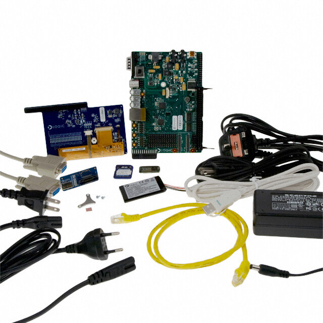
ICGOO电子元器件商城为您提供TRK-MPC5634M由Freescale Semiconductor设计生产,在icgoo商城现货销售,并且可以通过原厂、代理商等渠道进行代购。 TRK-MPC5634M价格参考¥1239.05-¥1239.05。Freescale SemiconductorTRK-MPC5634M封装/规格:评估板 - 嵌入式 - MCU,DSP, MPC5634M StarterTRAK Qorivva MCU 32-Bit e200 Embedded Evaluation Board。您可以下载TRK-MPC5634M参考资料、Datasheet数据手册功能说明书,资料中有TRK-MPC5634M 详细功能的应用电路图电压和使用方法及教程。
TRK-MPC5634M 是由 NXP USA Inc. 生产的一款评估板,主要用于嵌入式系统的开发与测试。该评估板基于 MPC5634M 微控制器(MCU),适用于多种应用场景,特别是在汽车电子和工业控制领域。

 1. 汽车电子应用
TRK-MPC5634M 在汽车电子中的主要应用场景包括:
- 动力总成控制:用于发动机管理和变速箱控制,确保车辆的动力传输系统高效运行。
- 车身控制模块 (BCM):管理车窗、车门锁、灯光等车身功能,提升驾驶体验和安全性。
- 安全系统:如防抱死制动系统(ABS)、电子稳定控制系统(ESC)等,保障车辆行驶安全。
- 新能源汽车:支持电动汽车的电池管理系统(BMS),监控电池状态并优化充电过程。

 2. 工业控制
在工业自动化领域,TRK-MPC5634M 可以用于:
- 电机控制:实现高效、精确的电机驱动和控制,适用于工厂自动化设备。
- 传感器数据采集:通过集成的 ADC 和 DAC 模块,实时采集和处理来自各种传感器的数据。
- 通信接口:支持 CAN、LIN 等工业标准通信协议,便于与其他设备进行数据交换。

 3. 嵌入式系统开发
TRK-MPC5634M 提供了一个完整的开发平台,方便工程师进行嵌入式系统的原型设计和调试:
- 丰富的外设接口:包括 UART、SPI、I2C 等接口,满足不同外设连接需求。
- 调试工具:内置 JTAG 接口,支持在线调试和编程,简化开发流程。
- 软件支持:提供完整的开发工具链和示例代码,帮助开发者快速上手。

 4. 教育和研究
TRK-MPC5634M 还可以用于教育和科研机构,作为教学工具或实验平台,帮助学生和研究人员了解嵌入式系统的工作原理和开发方法。

总之,TRK-MPC5634M 评估板凭借其强大的性能和丰富的功能,广泛应用于汽车电子、工业控制以及嵌入式系统开发等多个领域,为开发者提供了便捷高效的开发环境。
| 参数 | 数值 |
| 产品目录 | 编程器,开发系统嵌入式解决方案 |
| 描述 | TRAK 5634M 144PN R2.1开发板和工具包 - 其他处理器 TRAK 5634M 144pn R2.1 |
| 产品分类 | 评估板 - 嵌入式 - MCU, DSP工程工具 |
| 品牌 | Freescale Semiconductor |
| 产品手册 | http://cache.freescale.com/webapp/sps/site/prod_summary.jsp?code=TRK-MPC5634M |
| 产品图片 |
|
| rohs | 符合RoHS无铅 / 符合限制有害物质指令(RoHS)规范要求 |
| 产品系列 | 嵌入式开发工具,嵌入式处理器开发套件,开发板和工具包 - 其他处理器,Freescale Semiconductor TRK-MPC5634MQorivva |
| 数据手册 | |
| 产品型号 | TRK-MPC5634M |
| 产品 | Demonstration Boards |
| 产品种类 | 开发板和工具包 - 其他处理器 |
| 其它名称 | TRKMPC5634M |
| 内容 | 板,电缆 |
| 商标 | Freescale Semiconductor |
| 商标名 | Tower System |
| 安装类型 | 固定 |
| 工作电源电压 | 9 VDC to 12 VDC |
| 平台 | StarterTRAK |
| 接口类型 | CAN, LIN, USB |
| 操作系统 | - |
| 板类型 | 评估平台 |
| 标准包装 | 1 |
| 核心处理器 | e200 |
| 类型 | MCU 32-位 |
| 设计资源 | |
| 配套使用产品/相关产品 | MPC5634M |


- 商务部:美国ITC正式对集成电路等产品启动337调查
- 曝三星4nm工艺存在良率问题 高通将骁龙8 Gen1或转产台积电
- 太阳诱电将投资9.5亿元在常州建新厂生产MLCC 预计2023年完工
- 英特尔发布欧洲新工厂建设计划 深化IDM 2.0 战略
- 台积电先进制程称霸业界 有大客户加持明年业绩稳了
- 达到5530亿美元!SIA预计今年全球半导体销售额将创下新高
- 英特尔拟将自动驾驶子公司Mobileye上市 估值或超500亿美元
- 三星加码芯片和SET,合并消费电子和移动部门,撤换高东真等 CEO
- 三星电子宣布重大人事变动 还合并消费电子和移动部门
- 海关总署:前11个月进口集成电路产品价值2.52万亿元 增长14.8%

PDF Datasheet 数据手册内容提取
None
Purchase Agreement P&E Microcomputer Systems, Inc. reserves the right to make changes without further notice to any products herein to improve reliability, function, or design. P&E Microcomputer Systems, Inc. does not assume any liability arising out of the application or use of any product or circuit described herein. This software and accompanying documentation are protected by United States Copyright law and also by International Treaty provisions. Any use of this software in violation of copyright law or the terms of this agreement will be prosecuted. All the software described in this document is copyrighted by P&E Microcomputer Systems, Inc. Copyright notices have been included in the software. P&E Microcomputer Systems authorizes you to make archival copies of the software and documentation for the sole purpose of back-up and protecting your investment from loss. Under no circumstances may you copy this software or documentation for the purpose of distribution to others. Under no conditions may you remove the copyright notices from this software or documentation. This software may be used by one person on as many computers as that person uses, provided that the software is never used on two computers at the same time. P&E expects that group programming projects making use of this software will purchase a copy of the software and documentation for each user in the group. Contact P&E for volume discounts and site licensing agreements. P&E Microcomputer Systems does not assume any liability for the use of this software beyond the original purchase price of the software. In no event will P&E Microcomputer Systems be liable for additional damages, including any lost profits, lost savings or other incidental or consequential damages arising out of the use or inability to use these programs, even if P&E Microcomputer Systems has been advised of the possibility of such damage. By using this software, you accept the terms of this agreement. © 2011 P&E Microcomputer Systems, Inc. “MS-DOS” and “Windows” are registered trademarks of Microsoft Corporation. “Freescale” and “ColdFire” are registered trademarks of Freescale, Inc. The Power Architecture and Power.org wordmarks and the Power and Power.org logos and related marks are trademarks and service marks licensed by Power.org. Qorivva is a registered trademark of Freescale Semiconductor. P&E Microcomputer Systems, Inc. 98 Galen St. Watertown, MA 02472 617-923-0053 http://www.pemicro.com Manual version 1.01, April 2011
1 INTRODUCTION............................................................................................1 1.1 Overview........................................................................................................1 1.2 Package Contents..........................................................................................1 1.3 Supported Devices.........................................................................................1 1.4 Recommended Materials...............................................................................1 1.5 Handling Precautions.....................................................................................2 2 HARDWARE FEATURES...............................................................................2 2.1 TRK-MPC5634M Board Features..................................................................2 2.2 On-Board Virtual USB Port.............................................................................4 2.3 TRK-MPC5634M Jumper/Connector Quick Reference..................................5 3 GETTING STARTED WITH THE TRK-MPC5634M.......................................9 4 SYSTEM SETUP..........................................................................................10 4.1 Overview......................................................................................................10 4.2 Operating System Requirements ................................................................10 4.3 Software Setup.............................................................................................10 4.4 Quick Startup................................................................................................11 4.5 Hardware Setup...........................................................................................11 5 OPERATING MODES...................................................................................12 5.1 Overview......................................................................................................12 5.2 Debug Mode.................................................................................................12 5.3 Run Mode.....................................................................................................12 5.4 External JTAG/Nexus Mode.........................................................................12 6 JUMPER SETTINGS....................................................................................13 6.1 System Power..............................................................................................13 6.2 I/O Pins.........................................................................................................13 6.3 Debug Mode.................................................................................................14 6.4 CAN Port......................................................................................................15 6.5 Virtual Serial Port.........................................................................................15 6.6 LIN Channels/Connectors............................................................................16 6.7 MCU.............................................................................................................18 6.8 Boot Configuration........................................................................................19 TRK-MPC5634M User Manual ii
6.9 Clock Selection.............................................................................................20 6.10 Push Buttons................................................................................................21 6.11 LED Display Port..........................................................................................22 6.12 DIL Switch.....................................................................................................22 6.13 Analog Input Enable.....................................................................................23 6.14 Photo Sensor Enable....................................................................................24 6.15 Reset Sources..............................................................................................24 6.16 OSJTAG Bootloader Enable.........................................................................25 6.17 eTPUA LED Enable......................................................................................25 7 TRK-MPC5634M CODE DEVELOPMENT SOFTWARE..............................26 7.1 Using CodeWarrior With The TRK-MPC5634M............................................26 7.2 Using P&E Software With The TRK-MPC5634M..........................................26 8 TRANSITIONING TO YOUR OWN TARGET...............................................26 8.1 Hardware Solutions At A Glance..................................................................27 8.2 Working With P&E’s Multilink Universal or USB Qorivva Multilink................28 8.3 Working With P&E’s Cyclone MAX...............................................................29 9 TROUBLESHOOTING..................................................................................30 9.1 TRK-MPC5634M Is Undetected...................................................................30 10 TRK-MPC5634M ERRATA (REV. A ONLY).................................................31 iii TRK-MPC5634M User Manual
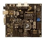
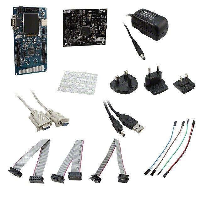
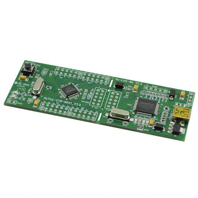
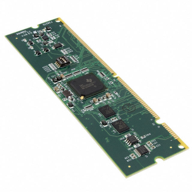
1 INTRODUCTION 1.1 Overview The TRK-MPC5634M is a low-cost development system supporting Freescale MPC5634M microcontrollers in 144LQFP packages. The Embedded OSJTAG circuitry on the TRK-MPC5634M board allows the processor on the board to be debugged and programmed via USB from a PC. In addition, the demo board can be powered using the USB bus. 1.2 Package Contents The TRK-MPC5634M package includes the following items: • TRK-MPC5634M Board • CodeWarrior Development Studio DVD-ROM • TRK-MPC5634M Resources CD • USB A-to-B Cable • Freescale Warranty Card 1.3 Supported Devices The TRK-MPC5634M supports the following devices: • MPC5634M microcontrollers in 144LQFP packages 1.4 Recommended Materials • Freescale MPC5634M reference manual and datasheet • TRK-MPC5634M board schematic TRK-MPC5634M EVB User Manual 1
1.5 Handling Precautions Please take care to handle the package contents in a manner such as to prevent electrostatic discharge. 2 HARDWARE FEATURES The TRK-MPC5634M is a demonstration and development system for Freescale’s MPC5634M microcontrollers in 144LQFP packages. Application development is quick and easy using Embedded OSJTAG. An optional 14-pin JTAG port is provided to allow the use of an external Qorivva MPC55xx/56xx interface such as P&E’s USB Multilink or Cyclone MAX automated programmer. P&E’s USB Multilink provides faster communication speeds and can be used to debug both the TRK-MPC5634M and the user’s own targets. Note: The DEMO board’s Embedded OSJTAG is intended to function with the on- board processor only. It cannot be used to communicate with other devices. 2.1 TRK-MPC5634M Board Features • Soldered MPC5634M LQFP144 device • Access to MCU pins with standard headers • Embedded OSJTAG: USB to JTAG circuitry which allows host PC to communicate with the microcontroller through USB 2.0. • On-board Virtual Serial Port • ON/OFF Power Switch w/ LED indicator • A 9VDC to 12VDC power supply input barrel connector • Power Input Selection Jumpers for selecting the input voltage source: • Power Input from USB Connector • Power Input from DC Power Jack • Freescale MC3390x • Jumper to select BAM source: • From internal memory • From CAN • From LIN Flex 2 TRK-MPC5634M EVB User Manual
• RESET Push Button and LED indicator w/ enable • User Features: • 4 User Push Buttons w/ enable and pull-up & pull-down options • 4 DIL switches w/ enable and pull-up & pull-down options • 10K Ohm POT connected to an ADC input channel w/ enable • 1 photocell w/ enable • 4 User LED’s w/ enable • 1 RS232 interface w/ enable (DB9 and transceiver footprint only) • 1 CAN interface w/ enable to high-speed CAN transceiver with DB9 CAN connector • 2 LIN channels w/ enable sharing one LIN transceiver with two standard LIN connectors • 4 distinct GND test points • Specifications: • Board Size 4.7” x 4.3” • Power Input: • USB Cable: 5VDC, 500mA max • DC Power Jack: 2.1/5.5mm barrel connector, 9VDC to 12VDC Center Positive TRK-MPC5634M EVB User Manual 3
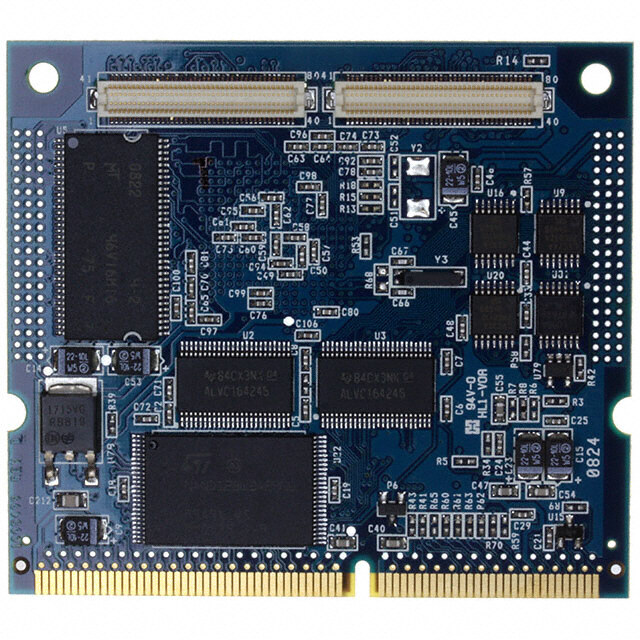
Figure 2-1: Top Component Placement 2.2 On-Board Virtual USB Port The TRK-MPC5634M board has a built-in virtual serial port which may be connected to the MPC5634M processor’s SCI RXD/TXD. This allows certain PC applications to be able to connect in a serial fashion to the microcontroller without the actual use of serial port hardware. 4 TRK-MPC5634M EVB User Manual
2.3 TRK-MPC5634M Jumper/Connector Quick Reference Default Jumper Settings The following is a list of default jumper settings for TRK-MPC5634M board. The settings listed indicate the “on” (or installed) position. Default Jumper Settings JUMPER OPTION SETTINGS DESCRIPTION USB OSJTAG Supplies 1-2 (default) 5VDC System Power J1 Source Select SBC MC33905 Supplies 2-3 5VDC 1-2 (default) Pull Up SBC I/O LED J2 Pull Up/Down 2-3 Pull Down 1-2 (default) I/O-0 J3 SBC I/O Signal 2-3 I/O-1 SBC DBG 1-2 Short SBC DBG Pin to GND, J4 Short to GND Bypass R21 and D13 (default: OFF) SBC DBG Pull Pull Up SBC DBG Pin to J5 Up 1-2 SBC Power Supply via 330 (default: OFF) Ohm Resistor CAN Signals to 1-2, 3-4 Enables TXD and RXD J6 Transceiver (default) signals to CAN Transceiver Enable TRK-MPC5634M EVB User Manual 5
Default Jumper Settings MCU TXD to Virtual Serial 1-2 (default) Port RS232 TXD J7 Signal MCU TXD to RS232 2-3 Transceiver MCU RXD to Virtual Serial 1-2 (default) Port RS232 RXD J8 Signal MCU RXD to RS232 2-3 Transceiver LIN1 VBus Provides Power to LIN1 J9 Enable 1-2 Connector (default: OFF) LIN0 VBus Provides Power to LIN0 J10 Enable 1-2 Connector (default: OFF) LIN0 Signals to 1-2 (default), Connects LIN0 Signals to J11 Connector 3-4 (default) LIN0 Connector Enable LIN1 Signals to Connector 1-2, 3-4 Connects LIN1 Signals to J12 Enable LIN1 Connector (default: OFF) 1-2 (default) MCU LIN0TX to Transceiver CT7 LIN TXD Signal 2-3 MCU LIN1TX to Transceiver 1-2 (default) MCU LIN0RX to Transceiver CT8 LIN RXD Signal 2-3 MCU LIN1RX to Transceiver 6 TRK-MPC5634M EVB User Manual
Default Jumper Settings shorrted Provides Power to MCU; CT1 Cut Trace (default) Current Measurement Cut traces on PCB board: Connects MCU SPI signals J16 SBC SPI 1-2 (default) to SBC SPI 3-4(default) 5-6(default) 7-8(default) External Crystal Circuitry Enable CT4 shorted Cut Trace XTAL (default) (default: ALL ON) External Crystal Circuitry Enable shorted CT5 Cut Trace EXTAL (default) (default: ALL ON) External Oscillator via J23 1-2 EXTAL SMA Enable (default: OFF) Push Button 1-2 (default) Active Low Active High or J24 Low; Opposite 2-3 Active High of J25 TRK-MPC5634M EVB User Manual 7
Default Jumper Settings Push Button 1-2 (default) Pull Up Pull Up/Down J25 Enable; 2-3 Pull Down Opposite of J24 Push Button 1-2 (default), Connects MCU Port Signals Enable 3-4 (default), EMIOS0, EMIOS2, EMIOS4, J26 (default: ALL 5-6 (default), and EMIOS8 to Push ON) 7-8 (default) Buttons Correspondingly LED Signals 1-2 (default), Connects MCU Port Enable 3-4 (default), EMIOS9, EMIOS10, J27 (default: ALL 5-6 (default), EMIOS11, and EMIOS12 to ON) 7-8 (default) LEDs Correspondingly DIL Switch 1-2 (default), Connects MCU Port Signals Enable 3-4 (default), eTPUA20, eTPUA21, J28 (default: ALL 5-6 (default), eTPUA22, and eTPUA23 to ON) 7-8 (default) DIL Switch Correspondingly DIL Switch 1-2 (default) Active High J29 Active High or Low 2-3 Active Low Analog Input Connects MCU AN17 to J30 1-2 (default) Enable Potentiometer Photo Sensor Connects MCU AN35 to J31 1-2 (default) Enable Photo Cell SBC Reset to Enables SBC Reset Signal J32 MCU Enable 1-2 to Trigger MCU Reset (default: OFF) OSJTAG Reset Enables OSJTAG Reset J33 1-2 (default) to MCU Enable Signal to Trigger MCU Reset 8 TRK-MPC5634M EVB User Manual
Default Jumper Settings System Reset Connects Reset Sources to CT9 1-2 (default) Enable MCU Reset Signal OSJTAG Forces OSJTAG to start up Bootloader J35 1-2 in bootloader mode for Enable firmware updates (default: OFF) Processor uses serial boot 1-2 mode J37 BOOTCFG1 Processor uses internal boot 2-3 (default) mode Processor uses a crystal 1-2 (default) clock source J38 PLLREF Processor uses an external 2-3 clock source Processor pins are 1-2 (default) configured as weak pull down CT2 WKPCFG Processor pins are 2-3 configured as weak pull up 2.4 External Power Supply Requirement DC Power Jack: Center Positive 2.1mm/5.5mm Barrel Connector Input Voltage Range: 9VDC to 12VDC Note: In order for LIN and CAN to operate properly, SBC must be powered externally. TRK-MPC5634M EVB User Manual 9
3 GETTING STARTED WITH THE TRK-MPC5634M The TRK-MPC5634M is a low-cost board targeting quick microcontroller evaluation. Please refer to the TRK-MPC5634M Quick Start Guide for instructions on how to install software, connect the TRK-MPC5634M to your PC, and run quick demonstrations. 4 SYSTEM SETUP 4.1 Overview The Embedded OSJTAG driver is required to operate the TRK-MPC5634M using a PC. The Embedded OSJTAG driver should be installed with the CodeWarrior Development Studio software before the PC is connected to the TRK-MPC5634M. Because new features and bug fixes are implemented frequently, it is strongly recommended that the user download and install the latest OSJTAG drivers from http://www.pemicro.com/osbdm. 4.2 Operating System Requirements The following are the resources required to run the CodeWarrior Development Studio and the TRK-MPC5634M: • A PC-compatible system running Windows 2000, Windows XP, Windows Vista, or Windows 7 • 128MB of available system RAM, and 1GB of available hard disk space • A DVD-ROM drive for software installation • A USB port 4.3 Software Setup 4.3.1 Installing CodeWarrior Development Studio To install the CodeWarrior Development Studio, follow the instructions on the DVD-ROM. 10 TRK-MPC5634M EVB User Manual
4.3.2 Installing P&E Resources Use the TRK-MPC5634M Resources in the DVD-ROM to access and install P&E resources for the DEMO board. These materials are not required for operation. The TRK-MPC5634M Resources CD-ROM contains the following support materials: • TRK-MPC5634M User Manual (this document) • TRK-MPC5634M Board Schematic • TRK-MPC5634M Component Breakdown List • P&E Evaluation Software • Links to Freescale documentation, P&E Discussion Forums, and TRK-MPC5634M FAQs. 4.4 Quick Startup Only a few steps are required to get the TRK-MPC5634M up and running. Please reference the Quick Start Guide. 4.5 Hardware Setup 4.5.1 First-Time Connection The TRK-MPC5634M may be connected to a PC through a USB port. Connection steps are listed below in typical order: 1. Install the required software, as described in the previous section. 2. Make sure the jumper USB_5V for POWER_SELECT is installed. 3. Plug the USB cable A-M connector into a free USB port of the PC. 4. Plug the USB cable B-M connector into the USB connector on the TRK-MPC5634M Board. 5. The operating system will recognize the Embedded OSJTAG circuitry and P&E’s USB to Serial circuitry. Depending on the operating sys- tem, you may see the “Found New Hardware Wizard” dialog to assist you with installation. Follow the onscreen Windows instructions to install the OSJTAG driver (these instructions may vary slightly depending on your specific operating system). 6. Select the “Install the software automatically (Recommended)” option TRK-MPC5634M EVB User Manual 11
and click the “Next” button. Windows will install the driver files to your system. At the end of the installation, click the “Finish” button. Note: Depending on the operating system, you may see the “Found New Hardware Wizard” dialog again to assist you with software installation for “PEMicro USB Serial Port (i1).” Follow the onscreen Windows instructions. 1. Select the “Install the software automatically (Recommended)” option and click the “Next” button. 2. Windows will install the driver files to your system. Click the “Finish” button to exit the “Found New Hardware Wizard.” If the TRK-MPC5634M hardware interface driver is now properly installed on your system, the green USB LED on the TRK-MPC5634M Base Board should be illuminated. In addition, if you turn on the system power of the TRK- MPC5634M you will see the yellow Power LED illuminate. 5 OPERATING MODES 5.1 Overview The TRK-MPC5634M’s Embedded OSJTAG circuitry, featured hardware components, and optional external JTAG header make it a versatile development tool. Below are some of the featured operating modes of the TRK-MPC5634M. 5.2 Debug Mode A host communicates with the TRK-MPC5634M through the Embedded OSJTAG circuitry. Either the CodeWarrior Development Studio or P&E’s Qorivva software tools will work with the TRK-MPC5634M. Please refer to Section 7 - TRK-MPC5634M CODE DEVELOPMENT SOFTWARE for more information. 5.3 Run Mode The TRK-MPC5634M’s rich component list empowers it to perform a variety of tasks. Once an application is developed, debugged, and programmed properly into the microcontroller’s internal flash memory, it can run with or without connecting to a host. 12 TRK-MPC5634M EVB User Manual
5.4 External JTAG/Nexus Mode The TRK-MPC5634M has an optional JTAG/Nexus header for debugging and programming the on-board MPC5634M microcontroller using an external Qorivva hardware tool, such as P&E’s USB Multilink or Cyclone MAX. Please refer to Section 8 - TRANSITIONING TO YOUR OWN TARGET for more information. A user can take advantage of this mode to develop a target- specific MPC5634M system and compare it with the TRK-MPC5634M when necessary. 6 JUMPER SETTINGS This section describes the various jumpers settings that are available on the TRK-MPC5634M. Figures depict the default setting for each jumper. Some board options are implemented as cut-trace options. To change from the default settings, the traces need to be cut and jumpers added to set the desired feature. 6.1 System Power The TRK-MPC5634M board provides 3 power options: SBC MC33905 or LDO can regulate external power to 5VDC, or USB can provide 5VDC through OSJTAG. 6.1.1 J1 - System Power 1-2 USB OSJTAG Supplies 5VDC (default) 3-4 SBC MC33905 Supplies 5VDC Figure 6-2: System Power (J1) TRK-MPC5634M EVB User Manual 13
6.2 I/O Pins The SBC MC33905 provides three I/O pins. Two of them are jumper (J3) selectable to two LEDs, which are further jumper (J2) selectable to pull-up or pull-down. 6.2.1 J2 - SBC I/O LED Pull Up/Down 1-2 Pull Up (default) 3-4 Pull Down Figure 6-3: SBC I/O LED Pull Up/Down (J2) 6.2.2 J3 - SBC I/O Signal 1-2 I/O-0 (default) 2-3 I/O-1 Figure 6-4: SBC I/O Signal (J3) 6.3 Debug Mode The SBC MC33905 has a DBG pin to put it into debug mode. Jumpers J4 and J5 are designed for this purpose. 6.3.1 J4 - SBC DBG Short To GND 1-2 Short SBC DBG Pin to GND, Bypass R21 and D13 (default: OFF) 14 TRK-MPC5634M EVB User Manual
Figure 6-5: SBC DBG Short To GND (J4) 6.3.2 J5 - SBC DBG Pull Up 1-2 Pull Up SBC DBG Pin to SBC Power Supply via 330 Ohm Resistor (default: OFF) Figure 6-6: SBC DBG Pull Up (J5) 6.4 CAN Port The TRK-MPC5634M board has implemented a CAN port. Note: In order for LIN and CAN to operate properly, SBC must be powered externally. 6.4.1 J6 – CAN Signals To Transceiver Enable CAN_EN Enables TXD and RXD signals to the CAN transceiver. By default, the jumpers are installed. Figure 6-7: CAN_EN (J6) 6.5 Virtual Serial Port The TRK-MPC5634M board has a built-in virtual serial port which may be connected to the MPC5504P processor’s SCI. This allows certain PC TRK-MPC5634M EVB User Manual 15
applications to be able to connect in a serial fashion to the microcontroller without the actual use of serial port hardware. It can be enabled or disabled by installing or removing the jumpers J7 and J8. 6.5.1 J7 - RS232 TXD Signal Figure 6-8: TXD_EN (J7) 6.5.2 J8 - RS232 RXD Signal Figure 6-9: RXD_EN (J8) 6.6 LIN Channels/Connectors The TRK-MPC5634M board provides two jumper selectable LIN channels to two jumper selectable LIN connectors. Note: In order for LIN and CAN to operate properly, SBC must be powered externally. 6.6.1 J9 - LIN1 VBus Enable 1-2 Provides Power to LIN1 Connector (default: OFF) Figure 6-10: LIN1 VBus Enable (J9) 16 TRK-MPC5634M EVB User Manual
6.6.2 J10 - LIN0 VBus Enable 1-2 Provides Power to LIN0 Connector (default: OFF) Figure 6-11: LIN0 VBus Enable (J10) 6.6.3 J11 - LIN0 Signals To Connector Enable 1-2, 3-4 Connects LIN0 Signals to LIN0 Connector (default) Figure 6-12: LIN0 Signals To Connector Enable (J11) 6.6.4 J12 - LIN1 Signals To Connector Enable 1-2, 3-4 Connects LIN1 Signals to LIN1 Connector (default: OFF) Figure 6-13: LIN1 Signals To Connector Enable (CT7) 6.6.5 CT7 - LIN TXD Signal 1-2 MCU LIN0TX to Transceiver (default) 2-3 MCU LIN1TX to Transceiver TRK-MPC5634M EVB User Manual 17
Figure 6-14: LIN TXD Signal (CT7) 6.6.6 CT8 - LIN RXD Signal 1-2 MCU LIN0RX to Transceiver (default) 2-3 MCU LIN1RX to Transceiver Figure 6-15: LIN RXD Signal (CT8) 6.7 MCU 6.7.1 CT1 - Cut Trace 1-2 shorted (default) Figure 6-16: MCU VDD Enable (CT1) 6.7.2 J16 - SBC_SPI Cut traces on PCB: 1-2 (default), 3-4 (default), 5-6 (default), 7-8 (default) - 18 TRK-MPC5634M EVB User Manual
connects MCU_SPI signals to SBC_SPI Figure 6-17: SBC_SPI (J16) 6.8 Boot Configuration 6.8.1 J37 - BOOTCFG1 1-2 Processor uses serial boot mode 2-3 Processor uses internal boot mode (default) Figure 6-18: BOOTCFG1 (J37) 6.8.2 J38 - PLLREF 1-2 Processor uses a crystal clock source (default) 2-3 Processor uses an external clock source Figure 6-19: PLLREF (J38) TRK-MPC5634M EVB User Manual 19
6.8.3 CT2 - WKPCFG 1-2 Processor pins are configured as weak pull down (default) 2-3 Processor pins are configured as weak pull up Figure 6-20: MPC5634M WKPCFG (CT2) 6.9 Clock Selection 6.9.1 CT4- External Crystal Circuitry Enable Cut Traces 1-2 XTAL (default: shorted) Figure 6-21: External Crystal Circuitry Enable (CT4) 6.9.2 CT5- External Crystal Circuitry Enable 1-2 EXTAL (default: shorted) Figure 6-22: External Crystal Circuitry Enable (CT5) 20 TRK-MPC5634M EVB User Manual
6.9.3 J23 - External Oscillator via SMA Enable 1-2 EXTAL (default: OFF) Figure 6-23: External Oscillator via SMA Enable (J23) 6.10 Push Buttons The TRK-MPC5634M board is designed with 4 jumper enabled push buttons with jumper selectable active high or low states. 6.10.1 J24 - Push Button Active High or Low (Opposite of J25) 1-2 Active Low (default) 2-3 Active High Figure 6-24: Push Button Active High or Low (J24) 6.10.2 J25 - Push Button Pull Up/Down Enable (Opposite of J24) 1-2 Pull Up (default) 2-3 Pull Down Figure 6-25: Push Button Pull Up/Down Enable (J25) TRK-MPC5634M EVB User Manual 21
6.10.3 J26 - Push Button Signals Enable 1-2, 3-4, 5-6, 7-8 Connects MCU Port EMIOS0, EMIOS2, EMIOS4 and EMIOS8 to Corresponding Push Buttons (default: ALL ON) Figure 6-26: Push Button Signals Enable (J26) 6.11 LED Display Port The TRK-MPC5634M has 4 LEDs connected to signals EMIOS9, EMIOS10, EMIOS11, and EMIOS12. They can be enabled or disabled by installing or removing the corresponding jumper, J27, in the LED_ENABLE header. 6.11.1 J27 - LED Display Enable Port LED_ENABLE Enables all LED outputs. This is the default setting. Figure 6-27: LED Display Enable Header LED_ENABLE (J27) 6.12 DIL Switch The TRK-MPC5634M board is designed with a 4 jumper-enabled DIL Switch signal with jumper-selectable active high or low states. 22 TRK-MPC5634M EVB User Manual
6.12.1 J28 - DIL Switch Signals 1-2, 3-4, 5-6, 7-8 Connects MCU Port eTPUA20, eTPUA21, eTPUA22, and eTPUA23 to Corresponding DIL Switch (default: ALL ON) Figure 6-28: DIL Switch Signals (J28) 6.12.2 J29 - DIL Switch Active High or Low 1-2 Active Low (default) 2-3 Active High Figure 6-29: DIL Switch Active High or Low (J29) 6.13 Analog Input Enable 6.13.1 J30 - Analog Input Enable 1-2 Connects MCU AN17 to Potentiometer (default) Figure 6-30: Analog Input Enable (J30) TRK-MPC5634M EVB User Manual 23
6.14 Photo Sensor Enable 6.14.1 J31 - Photo Sensor Enable 1-2 Connects MCU AN35 to Photo Sensor (default) Figure 6-31: Photo Sensor Enable (J31) 6.15 Reset Sources The TRK-MPC5634M board is designed with 3 reset sources: From SBC MC33905, from OSJTAG, and from the Reset Button. 6.15.1 J32 - SBC Reset to MCU Enable 1-2 Enables SBC Reset Signal to Trigger MCU Reset (default: OFF) Figure 6-32: SBC Reset to MCU Enable (J32) 6.15.2 J33 - OSJTAG Reset to MCU Enable 1-2 Enables OSJTAG Reset Signal MCU Reset (default) Figure 6-33: OSJTAG Reset to MCU Enable (J33) 24 TRK-MPC5634M EVB User Manual
6.15.3 CT9 - System Reset Enable 1-2 Connects Reset Sources to MCU Reset Signal (default) Figure 6-34: System Reset Enable (CT9) 6.16 OSJTAG Bootloader Enable 6.16.1 J35 - OSJTAG Bootloader Enable 1-2 Forces OSJTAG to start up in bootloader mode for firmware updates (default: OFF) Figure 6-35: OSJTAG IRQ Enable (J35) 6.17 eTPUA LED Enable 6.17.1 J39 - eTPUA LED Enable 1-2 Connects MCU eTPUA2 to LED (default) 3-4 Connects MCU eTPUA5 to LED (default) Figure 6-36: eTPUA LED Enable (J39) TRK-MPC5634M EVB User Manual 25
7 TRK-MPC5634M CODE DEVELOPMENT SOFTWARE The TRK-MPC5634M includes P&E’s OSJTAG circuitry, so no external Qorivva hardware tool is needed to debug and program the TRK-MPC5634M. A user only needs to connect the TRK-MPC5634M to their PC to start developing code for it. The TRK-MPC5634M package comes with a special edition of Freescale’s CodeWarrior studio. In addition, P&E’s evaluation software for Qorivva is available in the TRK-MPC5634M Resources section of the TRK-MPC5634M Resources CD, or online at www.pemicro.com. A user may use either CodeWarrior or P&E software tools to develop code for the TRK-MPC5634M. 7.1 Using CodeWarrior With The TRK-MPC5634M The CodeWarrior studio supports Freescale’s Qorivva devices. It offers C, C++, and assembly-level support, and provides debugging capabilities based on P&E’s debug and programming technologies. A programming or debug session with the project-based CodeWarrior IDE may be launched by double-clicking on the project name (the format is projectname.mcp) from your file storage. Its tutorials, FAQs, and quick start guides are easy to follow and will allow you use pre-built templates to begin creating a new project in a short time. Codewarrior tutorials can be followed based on the instructions provided. 7.2 Using P&E Software With The TRK-MPC5634M P&E offers an integrated development environment for Freescale’s Qorivva devices, which combines a GNU C compiler, in-circuit debugger, and flash memory programmer. The debugger supports both assembly and C source- level debugging. The programmer can program/reprogram both internal and external flash devices in-circuit. 8 TRANSITIONING TO YOUR OWN TARGET Once you have finished working with the TRK-MPC5634M and are ready to build your own target, you will need a hardware tool to allow you to develop using your own board. The Multilink Universal and USB Qorivva Multilink are development tools that are functionally comparable to the Embedded Multilink circuitry on the TRK- 26 TRK-MPC5634M EVB User Manual
MPC5634M. Either interface will enable you to debug your code and program it onto your target. The Cyclone MAX is a more versatile and robust development tool with advanced features and production capabilities. These solutions all work with Freescale’s CodeWarrior as well as P&E software, and provide a seamless transition to working with your own hardware. More information is available below to assist you in choosing the appropriate development tool for your needs. 8.1 Hardware Solutions At A Glance The Multilink Universal and USB Qorivva Multilink each offer an affordable and compact solution for your development needs, and allow debugging and programming to be accomplished simply and efficiently. Those doing rapid development will find these interfaces easy to use and fully capable of fast- paced debugging and programming. The Cyclone MAX is a more complete solution designed for both development and production. The Cyclone MAX features automated power switching, multiple communications interfaces (including USB, Ethernet, and Serial), stand-alone programming functionality, and many other advanced capabilities. Below is an overview of the features and intended use of the Multilink Universal and USB Qorivva Multilink, as well as the Cyclone MAX. 8.1.1 Multilink Universal and USB Qorivva Multilink Features • Direct user control of target’s execution • Programming and debugging capabilities • Read/write registers and memory values • Compact and lightweight • Communication via USB 2.0 • Supported by P&E software and Freescale’s CodeWarrior • USB Qorivva Multilink supports Freescale Qorivva MPC55xx/56xx. • Multilink Universal supports Freescale Qorivva MPC55xx/56xx, HCS08, HC(S)12(X), RS08, ColdFire V1/+V1, ColdFire V2-4, and Kinetis ARM. TRK-MPC5634M EVB User Manual 27
8.1.2 Cyclone MAX Key Features Advanced programming and debugging capabilities, including: • PC-Controlled and User-Controlled Stand-Alone Operation • Interactive Programming via Host PC • In-Circuit Debugging, Programming, and Testing • Compatible with Freescale’s ColdFireV2/3/4, Power Architecture 5xx/ 8xx, Qorivva MPC55xx/56xx, and Kinetis ARM microcontroller families • Communication via USB, Serial, and Ethernet Ports • Multiple image storage • LCD screen menu interface • Supported by P&E software and Freescale’s CodeWarrior 8.2 Working With P&E’s Multilink Universal or USB Qorivva Multilink Figure 8-1: Multilink Universal (left) & USB Qorivva Multilink (right) 8.2.1 Product Features & Implementation P&E’s Multilink Universal and USB Qorivva Multilink each connect your target to your PC and allow the PC access to the debug mode on Freescale’s Qorivva MPC55xx/56xx microcontrollers (the Multilink Universal also supports several other Freescale processors). These interfaces connect between a USB port on a Windows 2000/XP/2003/Vista/7 machine and a standard 14- pin JTAG/Nexus connector on the target. By using either of these interfaces, the user can take advantage of the background debug mode to halt normal processor execution and use a PC to control the processor. The user can then directly control the target’s 28 TRK-MPC5634M EVB User Manual
execution, read/write registers and memory values, debug code on the processor, and program internal or external FLASH memory devices. The Multilink Universal and USB Qorivva Multilink each enable you to debug, program, and test your code on your board. 8.2.2 Software The Multilink Universal and USB Qorivva Multilink interfaces each work with Codewarrior as well as P&E’s in-circuit debugger and flash programmer to allow debug and flash programming of the target processor. P&E’s USB Qorivva Multilink Development Packages come with the USB Qorivva Multilink interface, as well as flash programming software, in-circuit debugging software, Windows IDE, and a register file editor. 8.3 Working With P&E’s Cyclone MAX Figure 8-2: P&E’s Cyclone MAX 8.3.1 Product Features & Implementation P&E’s Cyclone MAX is an extremely flexible tool designed for debugging, testing, and in-circuit flash programming of Freescale’s ColdFireV2/3/4, Power Architecture 5xx/8xx, Qorivva MPC55xx/56xx, and Kinetis ARM microcontrollers. The Cyclone MAX connects your target to the PC via USB, Ethernet, or Serial Port and enables you to debug your code, program, and test it on your board. After development is complete the Cyclone MAX can be used as a production tool on your manufacturing floor. For production, the Cyclone MAX may be operated interactively via Windows- based programming applications as well as under batch or .dll commands from a PC. Once loaded with data by a PC it can be disconnected and operated manually in a stand-alone mode via the LCD menu and control buttons. The Cyclone MAX has over 7Mbytes of non-volatile memory, which TRK-MPC5634M EVB User Manual 29
allows the on-board storage of multiple programming images. When connected to a PC for programming or loading it can communicate via the ethernet, USB, or serial interfaces. 8.3.2 Software The Cyclone MAX comes with intuitive configuration software and interactive programming software, as well as easy to use automated control software. The Cyclone MAX also functions as a full-featured debug interface, and is supported by Freescale’s CodeWarrior as well as development software from P&E. P&E’s Cyclone MAX is also available bundled with additional software as part of various Development Packages. In addition to the Cyclone MAX, these Development Packages include in-circuit debugging software, flash programming software, a Windows IDE, and a register file editor. 9 TROUBLESHOOTING 9.1 TRK-MPC5634M Is Undetected Q: The connection assistant indicates that my TRK-MPC5634M is undetected even though I have connected the hardware to my USB port. What should I do? A: The connection assistant, which displays in either Codewarrior or P&E’s development software, is a dialog which allows the user to connect to the TRK-MPC5634M hardware. If this dialog indicates that the TRK-MPC5634M hardware is not connected to the PC, the first step is to make sure that the TRK-MPC5634M hardware is connected to the PC via a USB 2.0 high-speed cable. If it is connected, unplug and then plug in the USB cable on the TRK- MPC5634M board and click refresh in the connection assistant. If the hardware still does not show up, try the following remedies: (A) Re-Install the USB driver If the Multilink device does not show up in the device manager, re-install the CodeWarrior Development Studio software from the DVD-ROM. After driver installation, unplug the TRK-MPC5634M from the PC and reboot the PC. When the reboot has completed, connect the interface to the PC with the USB 2.0 cable. Run the software again to see if the interface is now detected. (B) USB Hub Usage 30 TRK-MPC5634M EVB User Manual
The TRK-MPC5634M is a high-power USB device. If a USB Hub is used, it must be a self-powered hub (i.e., with its own power supply). If the Hub is not self-powered the TRK-MPC5634M will not work. In general, USB ports located directly on the PC are high-power (self-powered) ports. 10 TRK-MPC5634M ERRATA (REV. A ONLY) The following errata should be noted for Rev. A of the TRK-MPC5634M. Workarounds are listed, when available. 1. VDDREG is floating. Workaround : Rev. A boards are shipped with an extra jumper between pins 5+6 of JP9 to connect VDDREG to the 5V power supply. 2. JCOMP is not connected on the 14-pin JTAG header (JP7) used for external debug tools. Workaround : Rev. A boards have a wire soldered to connect the JCOMP signal. If the user wishes to install the Nexus/Mictor connector, this wire may need to be removed. OSJTAG is not affected by this erratum. 3. OSJTAG is operating at 5V debug logic instead of 3.3V. No workaround available. However, this should not affect OSJTAG debug functionality. 4. J1 Silkscreen incorrect. The J1 silkscreen text for the system power source selection (USB vs. SBC) is incorrectly swapped. Pins 1+2 select SBC power, but the silkscreen indicates USB power. Likewise, pins 2+3 select USB power, but the silkscreen indicates SBC power. 5. J7 and J8 jumpers not populated by default. Workaround : Install 1x3 headers onto J7 and J8. These jumpers are required to connect the processor's TXD and RXD signals to the OSJTAG virtual serial port. 6. Wrong barrel size for JP1. On Rev. A boards, the barrel connector for JP1 is 2.5mm/5.5mm instead of 2.1mm/5.5mm. TRK-MPC5634M EVB User Manual 31
Workaround : Use a 2.5mm/5.5mm barrel power supply. 7. J16 jumpers not populated by default Workaround : Install 2x4 header onto J16. These jumpers are required to connect the processor's SPI signals to the SBC MC33905. Future revisions will implement this as cut traces. 32 TRK-MPC5634M EVB User Manual
None