
 Datasheet下载
- 型号: TPSMA6L36A
- 制造商: Littelfuse
- 库位|库存: xxxx|xxxx
- 要求:
| 数量阶梯 | 香港交货 | 国内含税 |
| +xxxx | $xxxx | ¥xxxx |
查看当月历史价格
查看今年历史价格
TPSMA6L36A产品简介:
ICGOO电子元器件商城为您提供TPSMA6L36A由Littelfuse设计生产,在icgoo商城现货销售,并且可以通过原厂、代理商等渠道进行代购。 TPSMA6L36A价格参考。LittelfuseTPSMA6L36A封装/规格:TVS - 二极管, 。您可以下载TPSMA6L36A参考资料、Datasheet数据手册功能说明书,资料中有TPSMA6L36A 详细功能的应用电路图电压和使用方法及教程。
TPSMA6L36A 是由 Littelfuse Inc. 生产的一款 TVS(瞬态电压抑制)二极管,其主要应用场景包括保护电子电路免受瞬态电压的损害。以下是该型号的具体应用场景及特点:

 1. 过电压保护
   - TPSMA6L36A 的最大反向工作电压为 36V,击穿电压为 40V,能够有效保护电路免受雷击、电感负载切换或静电放电(ESD)等引起的瞬态电压冲击。
   - 常用于电源线、信号线和数据线的过压保护。

 2. 通信设备
   - 在通信系统中,TPSMA6L36A 可以保护接口电路(如 RS-232、RS-485、USB 等)免受外部电压干扰。
   - 适用于路由器、调制解调器、基站和其他通信设备中的信号线路保护。

 3. 汽车电子
   - 在汽车电子系统中,该器件可用于保护车载电子控制单元(ECU)、传感器接口和 CAN 总线等免受电压波动的影响。
   - 能够承受较高的浪涌电流(峰值脉冲电流可达 17.4A),适合汽车环境中常见的电压瞬变。

 4. 工业控制
   - 工业自动化设备中的继电器、电机驱动器和开关电源需要可靠的过压保护,TPSMA6L36A 可以提供快速响应的保护功能。
   - 其双向设计使其适合交流信号线路的保护。

 5. 消费电子产品
   - 在家用电器、音频/视频设备和计算机外围设备中,TPSMA6L36A 可以保护输入/输出端口免受静电放电和电压尖峰的影响。
   - 例如,保护 HDMI、VGA 或其他接口免受外部电压干扰。

 6. 医疗设备
   - 医疗设备对可靠性和安全性要求极高,TPSMA6L36A 可用于保护敏感电路免受瞬态电压的损害,确保设备稳定运行。

 特点总结:
   - 快速响应时间(典型值小于 1ps),能够迅速抑制瞬态电压。
   - 高浪涌电流能力,适合严苛环境下的应用。
   - 小型封装(DO-214AC/AAB),便于在紧凑设计中使用。

综上所述,TPSMA6L36A 广泛应用于需要高可靠性电压保护的场景,特别是在通信、汽车、工业和消费电子领域。
| 参数 | 数值 |
| 产品目录 | |
| 描述 | TVS DIODE 36VWM 58.1VC SMA |
| 产品分类 | |
| 品牌 | Littelfuse Inc |
| 数据手册 | |
| 产品图片 |
|
| 产品型号 | TPSMA6L36A |
| rohs | 无铅 / 符合限制有害物质指令(RoHS)规范要求 |
| 产品系列 | TPSMA6L |
| 不同频率时的电容 | - |
| 供应商器件封装 | DO-221AC |
| 其它名称 | F6163DKR |
| 功率-峰值脉冲 | 600W |
| 包装 | Digi-Reel® |
| 单向通道 | 1 |
| 双向通道 | - |
| 安装类型 | 表面贴装 |
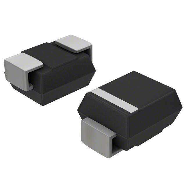
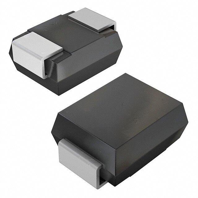
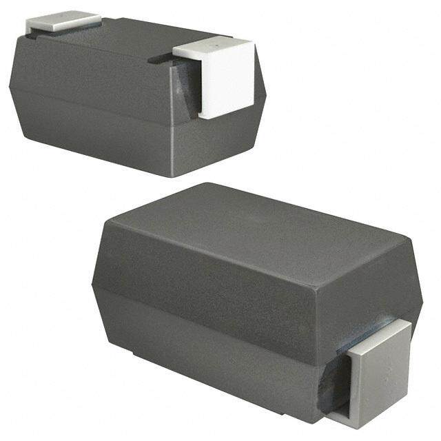
| 封装/外壳 | DO-221AC,SMA 扁平引线 |
| 工作温度 | -65°C ~ 150°C (TJ) |
| 应用 | 通用 |
| 标准包装 | 1 |
| 特色产品 | http://www.digikey.cn/product-highlights/zh/tpsma6l-series-tvs-diodes-600-w-aecq-qualified/51254 |
| 电压-击穿(最小值) | 40V |
| 电压-反向关态(典型值) | 36V |
| 电压-箝位(最大值)@Ipp | 58.1V |
| 电流-峰值脉冲(10/1000µs) | 10.4A |
| 电源线路保护 | 无 |
| 类型 | 齐纳 |


- 商务部:美国ITC正式对集成电路等产品启动337调查
- 曝三星4nm工艺存在良率问题 高通将骁龙8 Gen1或转产台积电
- 太阳诱电将投资9.5亿元在常州建新厂生产MLCC 预计2023年完工
- 英特尔发布欧洲新工厂建设计划 深化IDM 2.0 战略
- 台积电先进制程称霸业界 有大客户加持明年业绩稳了
- 达到5530亿美元!SIA预计今年全球半导体销售额将创下新高
- 英特尔拟将自动驾驶子公司Mobileye上市 估值或超500亿美元
- 三星加码芯片和SET,合并消费电子和移动部门,撤换高东真等 CEO
- 三星电子宣布重大人事变动 还合并消费电子和移动部门
- 海关总署:前11个月进口集成电路产品价值2.52万亿元 增长14.8%


PDF Datasheet 数据手册内容提取
TVS Diodes Surface Mount – 600W > TPSMA6L series TPSMA6L Series RoHS Pb e3 Uni-directional Description The TPSMA6L series is designed specifically to protect sensitive electronic equipment from voltage transients induced by load dump and other transient voltage events, and it’s especially suitable for high reliability and automotive application. SMA low profile package (DO221-AC) has the same electronical performance as the SMB package but with low height profiles (1.1mm). Agency Approvals Features AGENCY AGENCY FILE NUMBER • Same power as standard clamping capability E230531 SMB devices (600 W) • Fast response time: • Hi reliability application typically less than 1.0ns and automotive grade from 0 Volts to V min BR Maximum Ratings and Thermal Characteristics AEC Q101 qualified • Built-in strain relief (T =25OC unless otherwise noted) • SMA low profile package: • Glass passivated junction A less than 1.1 mm • High temperature Parameter Symbol Value Unit • Footprint compatibility soldering: 260°C/10 Peak Pulse Power Dissipation at T =25ºC by 10x1000µs Waveform P 600 W with standard SMA and seconds at terminals (FAig.2)(Note 1), (Note 2) PPM SMB products (easy to • Plastic package has layout) Power Dissipation on Infinite Heat underwriters laboratory P 3 W Sink at T =50OC M(AV) • Typical failure mode is flammability V-0 A short from over-specified Peak Forward Surge Current, 8.3ms • Typical maximum Single Half Sine Wave (Note 3) IFSM 60 A voltage or current temperature coefficient Maximum Instantaneous Forward • Whisker test is conducted ΔV = 0.1% x V @25°C x ΔT BR BR Voltage at 25A for Unidirectional V 3.5V V based on JEDEC F • Matte tin lead–free plated Only JESD201A per its table 4a • Halogen free and RoHS Operating Junction and Storage and 4c T, T -65 to 150 °C Temperature Range J STG compliant • IEC-61000-4-2 ESD Typical Thermal Resistance Junction 15kV(Air), 8kV (Contact) • Pb-free E3 means 2nd R 35 °C/W to Lead uJL level interconnect is • ESD protection of data Pb-free and the terminal Typical Thermal Resistance Junction lines in accordance with to Ambient RuJA 200 °C/W IEC 61000-4-2 finish material is tin(Sn) (IPC/JEDEC J-STD- • EFT protection of data Notes: 609A.01) lines in accordance with 1. Non-repetitive current pulse, per Fig.4 and derated above T=25ºC per Fig. 3. A IEC 61000-4-4 2. Mounted on 5.0x5.0mm copper pad to each terminal. 3. Measured on 8.3ms single half sine wave or equivalent square wave for unidirectional • Low inductance, excellent device only. Functional Diagram Applications Bi-directional TVS devices are ideal for the protection of I/O Interfaces, V bus and other vulnerable circuits used in Telecom, CC Computer, Industrial and Consumer electronic applications. Cathode Anode Uni-directional © 2016 Littelfuse, Inc. Specifications are subject to change without notice. Revised: 09/10/16
TVS Diodes Surface Mount – 600W > TPSMA6L series Electrical Characteristics Breakdown Test Maximum Maximum Reverse Maximum Agency NuPmarbt e r Marking Stand off Voltage VBR Current VColaltmagpein Vg Peak Pulse LReaekvaegrsee I Approcal (Uni) Vo(lVtaogltes )VR (Volts) @ IT IT @ Ipp C Curr(eAn)t Ipp @ VR R MIN MAX (mA) (V) (µA) TPSMA6L5.0A AEA 5.0 6.40 7.00 10 9.2 65.3 800 X TPSMA6L6.0A AGA 6.0 6.67 7.37 10 10.3 58.3 800 X TPSMA6L6.5A AKA 6.5 7.22 7.98 10 11.2 53.6 500 X TPSMA6L7.0A AMA 7.0 7.78 8.60 10 12.0 50.0 200 X TPSMA6L7.5A APA 7.5 8.33 9.21 1 12.9 46.6 100 X TPSMA6L8.0A ARA 8.0 8.89 9.83 1 13.6 44.2 50 X TPSMA6L8.5A ATA 8.5 9.44 10.40 1 14.4 41.7 20 X TPSMA6L9.0A AVA 9.0 10.00 11.10 1 15.4 39.0 10 X TPSMA6L10A AXA 10.0 11.10 12.30 1 17.0 35.3 5 X TPSMA6L11A AZA 11.0 12.20 13.50 1 18.2 33.0 1 X TPSMA6L12A BEA 12.0 13.30 14.70 1 19.9 30.2 1 X TPSMA6L13A BGA 13.0 14.40 15.90 1 21.5 28.0 1 X TPSMA6L14A BKA 14.0 15.60 17.20 1 23.2 25.9 1 X TPSMA6L15A BMA 15.0 16.70 18.50 1 24.4 24.6 1 X TPSMA6L16A BPA 16.0 17.80 19.70 1 26.0 23.1 1 X TPSMA6L17A BRA 17.0 18.90 20.90 1 27.6 21.8 1 X TPSMA6L18A BTA 18.0 20.00 22.10 1 29.2 20.6 1 X TPSMA6L20A BVA 20.0 22.20 24.50 1 32.4 18.6 1 X TPSMA6L22A BXA 22.0 24.40 26.90 1 35.5 16.9 1 X TPSMA6L24A BZA 24.0 26.70 29.50 1 38.9 15.5 1 X TPSMA6L26A CEA 26.0 28.90 31.90 1 42.1 14.3 1 X TPSMA6L28A CGA 28.0 31.10 34.40 1 45.4 13.3 1 X TPSMA6L30A CKA 30.0 33.30 36.80 1 48.4 12.4 1 X TPSMA6L33A CMA 33.0 36.70 40.60 1 53.3 11.3 1 X TPSMA6L36A CPA 36.0 40.00 44.20 1 58.1 10.4 1 X TPSMA6L40A CRA 40.0 44.40 49.10 1 64.5 9.3 1 X TPSMA6L43A CTA 43.0 47.80 52.80 1 69.4 8.7 1 X TPSMA6L45A CVA 45.0 50.00 55.30 1 72.7 8.3 1 X TPSMA6L48A CXA 48.0 53.30 58.90 1 77.4 7.8 1 X TPSMA6L51A CZA 51.0 56.70 62.70 1 82.4 7.3 1 X TPSMA6L54A REA 54.0 60.00 66.30 1 87.1 6.9 1 X TPSMA6L58A RGA 58.0 64.40 71.20 1 93.6 6.5 1 X TPSMA6L60A RKA 60.0 66.70 73.70 1 96.8 6.2 1 X TPSMA6L64A RMA 64.0 71.10 78.60 1 103.0 5.9 1 X TPSMA6L70A RPA 70.0 77.80 86.00 1 113.0 5.3 1 X TPSMA6L75A RRA 75.0 83.30 92.10 1 121.0 5.0 1 X TPSMA6L78A RTA 78.0 86.70 95.80 1 126.0 4.8 1 X TPSMA6L85A RVA 85.0 94.40 104.00 1 137.0 4.4 1 X © 2016 Littelfuse, Inc. Specifications are subject to change without notice. Revised: 09/10/16
TVS Diodes Surface Mount – 600W > TPSMA6L series I-V Curve Characteristics Uni-directional Vc VBRVR V IRVF IT Ipp P Peak Pulse Power Dissipation -- Max power dissipation PPM V Stand-off Voltage -- Maximum voltage that can be applied to the TVS without operation R V Breakdown Voltage -- Maximum voltage that flows though the TVS at a specified test current (I) BR T V Clamping Voltage -- Peak voltage measured across the suppressor at a specified Ippm (peak impulse current) C I Reverse Leakage Current -- Current measured at V R R V Forward Voltage Drop for Uni-directional F Ratings and Characteristic Curves (T=25°C unless otherwise noted) A Figure 1 - TVS Transients Clamping Waveform Figure 2 - Peak Pulse Power Rating Curve 100 Voltage Transients W) k Voltage Across TVS er ( 10 nt w urre Po e or C Current Through TVS ulse g P Volta eak 1 P -M PPP 0.2x0.2" (5.0x5.0mm) Copper Pad Area 0.1 0.001 0.01 0.1 1 Time t-Pulse Width (ms.) d continues on next page. © 2016 Littelfuse, Inc. Specifications are subject to change without notice. Revised: 09/10/16
TVS Diodes Surface Mount – 600W > TPSMA6L series Ratings and Characteristic Curves (T=25°C unless otherwise noted) (Continued) A Figure 3 - Pulse Derating Curve Figure 4 - Pulse Waveform 100 150 Pulse Power (P)) or Current (IPPPPDerating in Percentage % 24680000 - Peak Pulse Current, % IMRSM 15000 tr=1PI0PeµPasMke cVaHIlPuaPelMf Va(lI Pu P1a2eTPac0sM usuJ / rd1=)ltrsh02eeee50nfi W °0tpnC dµioedeisdtnceh tabc( wyt.yds hW ) R teiosar. E ev5d .0eteAh%ffieon orpemfde IaPkP M ak IPP e P td 0 0 0 25 50 75 100 125 150 175 0 1.0 2.0 3.0 4.0 TJ - Initial Junction Temperature (ºC) t-Time (ms) Figure 5 - Typical Junction Capacitance Figure 6 - Steady State Power Dissipation Derating Curve W) 3.6 10000 n ( o RuJA=RuJL ati 3.0 p si 1000 Uni-directional V=0V Dis 2.4 er w Cj (pF) 100 Uni-directional @VR ate Po 1.8 y St 1.2 10 ad e RuJA=200°C/W Tj=25ºC St 0.6 1 fV=s1ig.0=M5H0mzVp-p P, M(AV) 0 1.0 10.0 100.0 1000.0 0 25 50 75 100 125 150 175 V - Reverse Breakdown Voltage (V) BR T - Ambient Temperature (ºC) A bargaining © 2016 Littelfuse, Inc. Specifications are subject to change without notice. Revised: 09/10/16
TVS Diodes Surface Mount – 600W > TPSMA6L series Soldering Parameters Reflow Condition Lead–free assembly TP tp - Temperature Min (T ) 150°C Ramp-up Critical Zone PA(TrvLee) rHtaoeg apete raakm-- TTpeim muepp e(rmraatietnu (rtLeoi qMmuaaidxxu )( sT( stTs(sm(e)mimna)x)p) 26300°C 0–/° sC1e8c0o nsde cmsax emperature (T)TTTss((mmTainLx)) Prethseat tL Ramp-dToLw nto TP T to T - Ramp-up Rate 3°C/second max S(max) L 25˚C - Temperature (T) (Liquidus) 217°C t 25˚C to Peak Reflow L Time (t) - Time (min to max) (t) 60 – 150 seconds s Peak Temperature (T) 260+0/-5 °C P Time within 5°C of actual peak 20 – 40 seconds Environmental Specifications Temperature (t) p Ramp-down Rate 6°C/second max Time 25°C to peak Temperature (T) 8 minutes Max. High Temp. Storage JESD22-A103 P Do not exceed 260°C HTRB JESD22-A108 Physical Specifications Temperature Cycling JESD22-A104 Weight 0.002 ounce, 0.061 gram MSL JEDEC-J-STD-020, Level 1 JEDEC DO-221AC Molded Plastic over glass Case passivated junction H3TRB JESD22-A101 Polarity Color band denotes cathode except Bipolar RSH JESD22-A111 Matte Tin-plated leads, Solderable per Terminal JESD22-B102D Dimensions Cathode Band Inches Millimeters C Dimensions Min Max Min Max A 0.156 0.181 3.950 4.600 A B B 0.189 0.220 4.800 5.600 C 0.049 0.069 1.250 1.750 G D 0.088 0.116 2.250 2.950 E E F E 0.030 0.059 0.750 1.500 D F 0.005 0.010 0.125 0.250 G 0.035 0.043 0.900 1.100 3.12 (0.123) 1.20 (0.047) 1.52 (0.060) Mounting Pad Layout © 2016 Littelfuse, Inc. Specifications are subject to change without notice. Revised: 09/10/16
TVS Diodes Surface Mount – 600W > TPSMA6L series Part Numbering System Part Marking System TPSMA6L xx A Cathode Band F 5% V VOLTAGE TOLERANCE Littelfuse Logo BR VR VOLTAGE XXX SERIES Marking Code YMXXX Trace Code Marking Y:Year Code M: Month Code XXX: Lot Code Packaging Component Packaging Packaging Part number Quantity Package Option Specification TPSMA6LxxA DO-221AC 3000 Tape & Reel – 12mm/7” tape EIA RS-481 Tape and Reel Specification 0.157 (4.0) 0.47 Cathode (12.0) 0.157 0.059 DIA Cover tape (4.0) (1.5) 7.0 (178) Dimensions are in inches 0.80 (20.2) (and millimeters). Arbor Hole Dia. Direction of Feed 0.49 (12.5) © 2016 Littelfuse, Inc. Specifications are subject to change without notice. Revised: 09/10/16