ICGOO在线商城 > 集成电路(IC) > PMIC - 稳压器 - 线性 > TPS7A3301KC

 Datasheet下载
- 型号: TPS7A3301KC
- 制造商: Texas Instruments
- 库位|库存: xxxx|xxxx
- 要求:
| 数量阶梯 | 香港交货 | 国内含税 |
| +xxxx | $xxxx | ¥xxxx |
查看当月历史价格
查看今年历史价格
TPS7A3301KC产品简介:
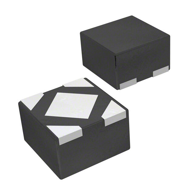
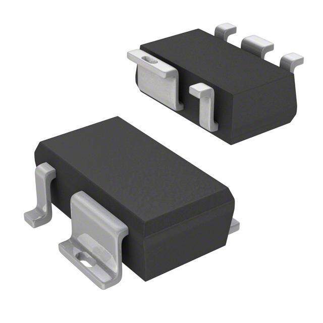
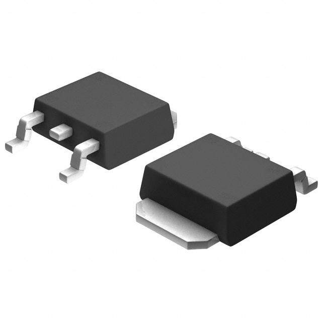
ICGOO电子元器件商城为您提供TPS7A3301KC由Texas Instruments设计生产,在icgoo商城现货销售,并且可以通过原厂、代理商等渠道进行代购。 TPS7A3301KC价格参考¥30.42-¥30.42。Texas InstrumentsTPS7A3301KC封装/规格:PMIC - 稳压器 - 线性, Linear Voltage Regulator IC Negative Adjustable 1 Output -1.18 V ~ -33 V 1A TO-220-7。您可以下载TPS7A3301KC参考资料、Datasheet数据手册功能说明书,资料中有TPS7A3301KC 详细功能的应用电路图电压和使用方法及教程。
TPS7A3301KC是德州仪器(Texas Instruments)生产的一款线性稳压器,属于PMIC(电源管理集成电路)类别。它具有低噪声、高精度和高稳定性的特点,适用于对电源要求较高的应用场景。

 应用场景

1. 通信设备:
   - TPS7A3301KC广泛应用于通信基站、无线模块和射频前端电路中。其低噪声特性可以有效减少对射频信号的干扰,确保通信质量。此外,该器件的高精度输出电压有助于提高系统的整体性能,特别是在需要稳定供电的高速数据传输场景中。

2. 医疗设备:
   - 在医疗电子设备中,如便携式医疗仪器、超声波设备和心电图机等,TPS7A3301KC能够提供稳定的电源供应,确保设备的准确性和可靠性。其低噪声特性对于敏感的医疗传感器尤为重要,可以避免电源波动对测量结果的影响。

3. 工业自动化:
   - 该稳压器在工业控制系统、可编程逻辑控制器(PLC)和传感器接口中也有广泛应用。它能够在恶劣的工业环境中提供稳定的电源,确保系统正常运行。同时,其紧凑的封装形式也便于集成到各种工业设备中。

4. 消费电子产品:
   - TPS7A3301KC适用于高端音频设备、智能家居产品和便携式电子设备。其低噪声和高精度特性可以提升音频质量和用户体验,尤其是在对音质有较高要求的耳机放大器和音响系统中。

5. 测试与测量设备:
   - 在精密测量仪器中,如示波器、信号发生器和频谱分析仪等,TPS7A3301KC能够提供稳定的电源,确保测量结果的准确性。其低噪声特性有助于减少外界干扰,提高测量精度。

6. 汽车电子:
   - 在汽车电子系统中,如车载信息娱乐系统、高级驾驶辅助系统(ADAS)和车身控制模块中,TPS7A3301KC能够提供可靠的电源支持,确保这些系统在复杂的工作环境中稳定运行。

总之,TPS7A3301KC凭借其低噪声、高精度和高稳定性等特点,适用于多种对电源要求苛刻的应用场景,特别是在需要稳定供电和高精度输出的场合中表现尤为出色。
| 参数 | 数值 |
| 产品目录 | 集成电路 (IC)半导体 |
| 描述 | IC REG LDO NEG ADJ 1A TO220-7线性稳压器 -3 to -36V,-1A,Ultra Low Noise,High PSRR |
| DevelopmentKit | TPS7A3301EVM-061 |
| 产品分类 | |
| 品牌 | Texas Instruments |
| 产品手册 | |
| 产品图片 |
|
| rohs | 符合RoHS无铅 / 符合限制有害物质指令(RoHS)规范要求 |
| 产品系列 | 电源管理 IC,线性稳压器,Texas Instruments TPS7A3301KC- |
| 数据手册 | |
| 产品型号 | TPS7A3301KC |
| 产品种类 | |
| 供应商器件封装 | TO-220-7 |
| 包装 | 管件 |
| 商标 | Texas Instruments |
| 安装类型 | 表面贴装 |
| 安装风格 | Through Hole |
| 封装 | Tube |
| 封装/外壳 | TO-220-7 |
| 封装/箱体 | TO-220-7 |
| 工作温度 | -40°C ~ 125°C |
| 工厂包装数量 | 50 |
| 最大工作温度 | + 125 C |
| 最大输入电压 | - 36 V |
| 最小工作温度 | - 40 C |
| 最小输入电压 | - 36 V |
| 标准包装 | 50 |
| 电压-跌落(典型值) | 0.325V @ 1A |
| 电压-输入 | -3 V ~ -36 V |
| 电压-输出 | -1.18 V ~ -33 V |
| 电流-输出 | 1A |
| 电流-限制(最小值) | - |
| 稳压器拓扑 | 负,可调式 |
| 稳压器数 | 1 |
| 系列 | TPS7A3301 |
| 输出电流 | 1 A |
| 输出类型 | Adjustable |

_4040251^B.jpg)


- 商务部:美国ITC正式对集成电路等产品启动337调查
- 曝三星4nm工艺存在良率问题 高通将骁龙8 Gen1或转产台积电
- 太阳诱电将投资9.5亿元在常州建新厂生产MLCC 预计2023年完工
- 英特尔发布欧洲新工厂建设计划 深化IDM 2.0 战略
- 台积电先进制程称霸业界 有大客户加持明年业绩稳了
- 达到5530亿美元!SIA预计今年全球半导体销售额将创下新高
- 英特尔拟将自动驾驶子公司Mobileye上市 估值或超500亿美元
- 三星加码芯片和SET,合并消费电子和移动部门,撤换高东真等 CEO
- 三星电子宣布重大人事变动 还合并消费电子和移动部门
- 海关总署:前11个月进口集成电路产品价值2.52万亿元 增长14.8%


PDF Datasheet 数据手册内容提取
Product Sample & Technical Tools & Support & Folder Buy Documents Software Community TPS7A33 SBVS169D–DECEMBER2011–REVISEDAPRIL2015 TPS7A33 –36-V, 1-A, Ultralow-Noise Negative Voltage Regulator 1 Features 3 Description • InputVoltageRange:–3Vto –36V The TPS7A33 series of linear regulators are negative 1 voltage (–36 V), ultralow-noise (16-μV , 72-dB • Noise: RMS PSRR) linear regulators capable of sourcing a – 16μVRMS(10Hzto100kHz) maximumloadof1A. • Power-SupplyRippleRejection: The TPS7A33 series include a complementary metal – 72dB(10kHz) oxide semiconductor (CMOS) logic-level-compatible • AdjustableOutput:–1.18Vto –33V enable pin (EN) to allow for user-customizable power management schemes. Other features available • MaximumOutputCurrent:1A include built-in current limit and thermal shutdown • StableWithCeramicCapacitors≥ 10μF features to protect the device and system during fault • Built-InCurrent-LimitandThermalShutdown conditions. Protection The TPS7A33 family is designed using bipolar • AvailableinanExternalHeatsink-Capable,High technology primarily for high-accuracy, high-precision ThermalPerformanceTO-220Package instrumentation applications, where clean voltage rails are critical to maximize system performance. • OperatingTemperatureRange: This feature makes it ideal to power operational –40°Cto125°C amplifiers, analog-to-digital converters (ADCs), digital-to-analog converters (DACs), and other high- 2 Applications performanceanalogcircuitry. • SupplyRailsforOperationalAmplifiers,DACs, In addition, the TPS7A33 family of linear regulators is ADCs,andOtherHigh-PrecisionAnalogCircuitry suitable for post DC-DC converter regulation. By • Audio filtering out the output voltage ripple inherent to DC- • PostDC-DCConverterRegulationandRipple DC switching conversion, maximum system performance is ensured in sensitive instrumentation, Filtering medical, test and measurement, audio, and RF • TestandMeasurement applications. • Medical For applications where positive and negative high- • IndustrialInstrumentation performance rails are required, consider the • BaseStationsandTelecomInfrastructure TPS7A4700 positivehigh-voltage,ultralow-noise,low- • 12-Vand24-VIndustrialBuses dropoutlinearregulatoraswell. DeviceInformation(1) PARTNUMBER PACKAGE BODYSIZE(NOM) TO-220(7) 10.17mm×8.38mm TPS7A33 VQFN(20) 5.00mm×5.00mm (1) For all available packages, see the orderable addendum at theendofthedatasheet. TypicalApplicationSchematic TPS7A47xx RF LDO Amplifier TPS7A33 Negative-Voltage Regulator 1 An IMPORTANT NOTICE at the end of this data sheet addresses availability, warranty, changes, use in safety-critical applications, intellectualpropertymattersandotherimportantdisclaimers.PRODUCTIONDATA.
TPS7A33 SBVS169D–DECEMBER2011–REVISEDAPRIL2015 www.ti.com Table of Contents 1 Features.................................................................. 1 8 ApplicationandImplementation........................ 15 2 Applications........................................................... 1 8.1 ApplicationInformation............................................15 3 Description............................................................. 1 8.2 TypicalApplication..................................................18 4 RevisionHistory..................................................... 2 8.3 Do'sandDon’ts.......................................................20 5 PinConfigurationandFunctions......................... 4 9 PowerSupplyRecommendations...................... 21 6 Specifications......................................................... 5 10 Layout................................................................... 21 6.1 AbsoluteMaximumRatings .....................................5 10.1 LayoutGuidelines.................................................21 6.2 ESDRatings ............................................................5 10.2 LayoutExample....................................................21 6.3 RecommendedOperatingConditions.......................5 10.3 ThermalPerformanceandHeatSinkSelection....24 6.4 ThermalInformation..................................................5 10.4 PackageMounting................................................25 6.5 ElectricalCharacteristics...........................................6 11 DeviceandDocumentationSupport................. 25 6.6 TypicalCharacteristics..............................................7 11.1 DeviceSupport......................................................25 7 DetailedDescription............................................ 12 11.2 DocumentationSupport........................................25 7.1 Overview.................................................................12 11.3 Trademarks...........................................................25 7.2 FunctionalBlockDiagram.......................................12 11.4 ElectrostaticDischargeCaution............................25 7.3 FeatureDescription.................................................12 11.5 Glossary................................................................25 7.4 DeviceFunctionalModes........................................14 12 Mechanical,Packaging,andOrderable Information........................................................... 26 4 Revision History NOTE:Pagenumbersforpreviousrevisionsmaydifferfrompagenumbersinthecurrentversion. ChangesfromRevisionC(February2013)toRevisionD Page • AddedESDRatingstable,FeatureDescriptionsection,DeviceFunctionalModes,ApplicationandImplementation section,PowerSupplyRecommendationssection,Layoutsection,DeviceandDocumentationSupportsection,and Mechanical,Packaging,andOrderableInformationsection ................................................................................................. 1 • Correctedtitleofdatasheettoshowaccuratemaximumoutputcurrent;changed"–1A"to"1-A" ..................................... 1 • Changedfront-pagefiguresanddeletednotestatingthatRGWpackagewasproductpreview........................................... 1 • ChangedPinConfigurationandFunctionssection;updatedtableformatanddeletedfootnoteaboutRGWproduct- previewstatus......................................................................................................................................................................... 4 • DeletedfootnotefromPinFunctionstableindicatingRGWproduct-previewstatus.............................................................. 4 • Deletedfootnote(2)fromAbsoluteMaximumRatingstable.................................................................................................. 5 • DeletednotefromThermalInformationtablestatingthatRGWpackagewasproductpreview .......................................... 5 • CorrectedconditionvaluesforFigure23............................................................................................................................... 9 • CorrectedconditionvaluesforFigure24............................................................................................................................... 9 • CorrectedconditionvaluesandtraceindicatorsforFigure25............................................................................................. 10 • CorrectedconditionvaluesandtraceindicatorsforFigure26............................................................................................. 10 • ChangedC valuefrom1µFto10nFinFigure27........................................................................................................... 10 SS • DeletedParametricMeasurementInformationsection ....................................................................................................... 12 • RevisedFunctionalBlockDiagram....................................................................................................................................... 12 • ChangedfirstparagraphofAdjustableOperationsectionstatingthedeviceoutputvoltagerange.................................... 15 • ChangedEquation2forclarity ............................................................................................................................................ 15 • ChangedlastsentenceofCapacitorRecommendationssection ........................................................................................ 16 • Changednoisereductioncapacitorvaluefrom1µFto10nFinfirstparagraphofPower-SupplyRejectionsection.........17 • RevisedlastparagraphofPower-SupplyRejectionsection................................................................................................. 17 • Changednoisereductioncapacitorvaluefrom1µFto10nFinsecondparagraphofOutputNoisesection....................17 • Addedfootnote(1)toFigure32........................................................................................................................................... 18 • ChangedtitleforFigure41................................................................................................................................................... 23 • ChangedtitleforFigure42................................................................................................................................................... 23 2 SubmitDocumentationFeedback Copyright©2011–2015,TexasInstrumentsIncorporated ProductFolderLinks:TPS7A33
TPS7A33 www.ti.com SBVS169D–DECEMBER2011–REVISEDAPRIL2015 Revision History (continued) • ChangedPowerDissipationsectiontitletoLayoutGuidelinesforThermalPerformanceandHeatSinkSelection ..........24 • RevisedwordinginLayoutGuidelinesforThermalPerformancesectionforclarification .................................................. 24 ChangesfromRevisionB(March2012)toRevisionC Page • ChangedproductstatusfromMixedStatustoProductionData............................................................................................ 1 • AddedlastparagraphinDescriptionsection.......................................................................................................................... 1 • Changedtypicalapplicationblockdiagram............................................................................................................................ 1 • UpdatedFigure31................................................................................................................................................................ 17 ChangesfromRevisionA(December2011)toRevisionB Page • ChangedproductstatusfromProductionDatatoMixedStatus............................................................................................ 1 • AddedRGWpinoutdrawing................................................................................................................................................... 1 • AddedRGWpinoutdrawingtoPinConfigurationandFunctionssection.............................................................................. 4 • AddedRGWandfootnote1toPinFunctionstable............................................................................................................... 4 • AddedRGWcolumntoThermalInformationtable................................................................................................................. 5 ChangesfromOriginal(December2011)toRevisionA Page • ChangedproductstatusfromProductPreviewtoProductionData....................................................................................... 1 Copyright©2011–2015,TexasInstrumentsIncorporated SubmitDocumentationFeedback 3 ProductFolderLinks:TPS7A33
TPS7A33 SBVS169D–DECEMBER2011–REVISEDAPRIL2015 www.ti.com 5 Pin Configuration and Functions KCPackage 7-PinTO-220 RGWPackage TopView 20-PinVQFN TopView T U C C C O N N N N I 0 9 8 7 6 2 1 1 1 1 OUT 1 15 IN NC 2 14 NR/SS Thermal FB 3 13 EN Pad 1 2 3 4 5 6 7 NC 4 12 NC NC 5 11 NC 6 7 8 9 10 EN IN NC FB C D C C C N N N N N NR/SS GND OUT G PinFunctions PIN I/O DESCRIPTION NAME TO-220 VQFN Thispinturnstheregulatoronoroff.IfV ≥V orV ≤V ,theregulatorisenabled. EN EN(+HI) EN EN(–HI) EN 1 13 I IfV ≥V ≥V ,theregulatorisdisabled.TheENpincanbeconnectedtoIN,ifnot EN(+LO) EN EN(–LO) used.|V |≤|V |. EN IN Thispinistheinputtothecontrol-looperroramplifier.Itisusedtosettheoutputvoltageofthe FB 7 3 I device.TIrecommendsconnectinga10-nFcapacitorfromFBtoOUT(asclosetothedeviceas possible)tomaximizeACperformance. GND 4 7 — Ground Inputsupply.Acapacitorgreaterthanorequalto10nFmustbetiedfromthispintogroundto assurestability.Itisrecommendedtoconnecta10-µFcapacitorfromINtoGND(asclosetothe IN 3 15,16 I deviceaspossible)toreducecircuitsensitivitytoprinted-circuit-board(PCB)layout,especially whenlonginputtracesorhighsourceimpedancesareencountered. 2,4-6,8- NC 5 — ThispincanbeleftopenortiedtoanyvoltagebetweenGNDandIN. 12,17-19 Noisereductionpin.AcapacitorconnectedfromthispintoGNDcontrolsthesoft-startfunction andallowsRMSnoisetobereducedtoverylowlevels.TIrecommendsconnectinga1-µF NR/SS 2 14 — capacitorfromNR/SStoGND(asclosetothedeviceaspossible)tofilterthenoisegeneratedby theinternalbandgapandmaximizeacperformance. Regulatoroutput.Acapacitorgreaterthanorequalto10µFmustbetiedfromthispintogroundto OUT 6 1,20 O assurestability.TIrecommendsconnectinga47-µFceramiccapacitorfromOUTtoGND(asclose tothedeviceaspossible)tomaximizeacperformance. Thermal Connectthethermalpadtoalarge-areagroundplane.Thethermalpadisinternallyconnectedto Tab — — Pad GND.Anexternalheatsinkcanbeinstalledtoprovideadditionalthermalperformance. 4 SubmitDocumentationFeedback Copyright©2011–2015,TexasInstrumentsIncorporated ProductFolderLinks:TPS7A33
TPS7A33 www.ti.com SBVS169D–DECEMBER2011–REVISEDAPRIL2015 6 Specifications 6.1 Absolute Maximum Ratings overoperatingfree-airtemperaturerange(unlessotherwisenoted) (1) MIN MAX UNIT INpintoGNDpin –36 0.3 OUTpintoGNDpin –33 0.3 OUTpintoINpin –0.3 36 FBpintoGNDpin –2 0.3 Voltage V FBpintoINpin –0.3 36 ENpintoGNDpin –36 10 NR/SSpintoINpin –0.3 36 NR/SSpintoGNDpin –2 0.3 Current Peakoutput Internallylimited Operatingvirtualjunction,TJ –40 150 Temperature °C Storagetemperature,Tstg –65 150 (1) StressesbeyondthoselistedunderAbsoluteMaximumRatingsmaycausepermanentdamagetothedevice.Thesearestressratings only,whichdonotimplyfunctionaloperationofthedeviceattheseoranyotherconditionsbeyondthoseindicatedunderRecommended OperatingConditions.Exposuretoabsolute-maximum-ratedconditionsforextendedperiodsmayaffectdevicereliability. 6.2 ESD Ratings VALUE UNIT Humanbodymodel(HBM),perANSI/ESDA/JEDECJS-001,allpins(1) ±1000 V(ESD) Electrostaticdischarge Chargeddevicemodel(CDM),perJEDECspecificationJESD22-C101,allpins(2) ±500 V (1) JEDECdocumentJEP155statesthat500-VHBMallowssafemanufacturingwithastandardESDcontrolprocess. (2) JEDECdocumentJEP157statesthat250-VCDMallowssafemanufacturingwithastandardESDcontrolprocess. 6.3 Recommended Operating Conditions overoperatingfree-airtemperaturerange(unlessotherwisenoted) MIN NOM MAX UNIT VIN Inputsupplyvoltage –35 –3 V VEN Enablesupplyvoltage VIN 10 V VOUT Outputvoltage –33.2 VREF V IOUT Outputcurrent 0 1 A R2(1) R2isthelowerfeedbackresistor 240 kΩ CIN Inputcapacitor 10 47 µF COUT Outputcapacitor 10 47 µF CNR Noisereductioncapacitor 1 µF CFF Feed-forwardcapacitor 10 nF TJ Operatingjunctiontemperature –40 125 °C (1) Thisconditionhelpsensurestabilityatnoload. 6.4 Thermal Information TPS7A33 THERMALMETRIC(1) KC(TO-220) RGW(VQFN) UNIT 7PINS 20PINS RθJA Junction-to-ambientthermalresistance 31.2 33.7 RθJC(top) Junction-to-case(top)thermalresistance 40 30.4 RθJB Junction-to-boardthermalresistance 17.4 12.5 °C/W ψJT Junction-to-topcharacterizationparameter 6.4 0.4 ψJB Junction-to-boardcharacterizationparameter 17.2 12.5 RθJC(bot) Junction-to-case(bottom)thermalresistance 0.8 2.4 (1) Formoreinformationabouttraditionalandnewthermalmetrics,seetheICPackageThermalMetricsapplicationreport,SPRA953. Copyright©2011–2015,TexasInstrumentsIncorporated SubmitDocumentationFeedback 5 ProductFolderLinks:TPS7A33
TPS7A33 SBVS169D–DECEMBER2011–REVISEDAPRIL2015 www.ti.com 6.5 Electrical Characteristics At–40°C≤T ≤125°C,|V |=|V |+1Vor|V |=3V(whicheverisgreater),V =V ,I =1mA,C =10μF,C =10μF, J IN OUT(nom) IN EN IN OUT IN OUT C =0nF,andFBtiedtoOUT,unlessotherwisenoted.(1) NR/SS PARAMETER TESTCONDITIONS MIN TYP MAX UNIT V Inputvoltage –35 –3 V IN V Internalreference T =25°C,V =V –1.192 –1.175 –1.157 V REF J FB REF V Undervoltagelockoutthreshold –2 V UVLO Outputvoltagerange(2) |V |≥|V |+1V –33.2 V V IN OUT(nom) REF Nominalaccuracy T =25°C,|V |=|V |+0.5V –1.5 1.5 %V J IN OUT(nom) OUT VOUT 5V≤|VIN|≤35V ±1 1mA≤I ≤1A OUT Overallaccuracy %V OUT |V |+1V≤|V |≤35V OUT(nom) IN –2.5 2.5 1mA≤I ≤1A OUT ΔV Lineregulation |V |+1V≤|V |≤35V 0.14 %V OUT(ΔVI) OUT(nom) IN OUT ΔV Loadregulation 1mA≤I ≤1A 0.4 %V OUT(ΔIL) OUT OUT V =95%V ,I =500mA 290 IN OUT(nom) OUT |V | Dropoutvoltage mV DO V =95%V ,I =1A 325 800 IN OUT(nom) OUT I Currentlimit V =90%V 1900 mA CL OUT OUT(nom) I =0mA 210 350 μA OUT I Groundcurrent GND I =500mA 5 mA OUT V =+0.4V 1 3 EN |I | Shutdownsupplycurrent μA SHDN V =–0.4V 1 3 EN I Feedbackcurrent(3) 14 100 nA FB V =|V |=|V |+1V 0.48 1 EN IN OUT(nom) |I | Enablecurrent V =V =–35V 0.51 1 μA EN IN EN V =–35V,V =+10V 0.5 1 IN EN V Positiveenablehigh-levelvoltage 2 10 V EN(+HI) V Positiveenablelow-levelvoltage 0 0.4 V EN(+LO) V Negativeenablehigh-levelvoltage V –2 V EN(–HI) IN V Negativeenablelow-levelvoltage –0.4 0 V EN(–LO) V =–3V,V =V ,C =22μF, V Outputnoisevoltage IN OUT(nom) REF OUT 16 μV n C =10nF,BW=10Hzto100kHz RMS NR/SS V =–6.2V,V =–5V,C =22μF, PSRR Power-supplyrejectionratio CIN =10nFO,UCT(no(4m))=10nF,fO=U1T0kHz 72 dB NR/SS FF Shutdown,temperatureincreasing 170 °C T Thermalshutdowntemperature sd Reset,temperaturedecreasing 150 °C T Operatingjunctiontemperature –40 125 °C J (1) Atoperatingconditions,V ≤0V,V ≤V ≤0V.Atregulation,V ≤V –|V |.I >0flowsfromOUTtoIN. IN OUT(nom) REF IN OUT(nom) DO OUT (2) Toensurestabilityatnoloadconditions,acurrentfromthefeedbackresistivenetworkequaltoorgreaterthan5μAisrequired. (3) I >0flowsintothedevice. FB (4) C referstoafeed-forwardcapacitorconnectedbetweentheFBandOUTpins. FF 6 SubmitDocumentationFeedback Copyright©2011–2015,TexasInstrumentsIncorporated ProductFolderLinks:TPS7A33
TPS7A33 www.ti.com SBVS169D–DECEMBER2011–REVISEDAPRIL2015 6.6 Typical Characteristics At–40°C≤T ≤125°C,|V |=|V |+1Vor|V |=3V(whicheverisgreater),V =V ,I =1mA,C =22μF,C J IN OUT(nom) IN EN IN OUT IN OUT =22μF,C =0nF,andtheFBpintiedtoOUT,unlessotherwisenoted. NR/SS −1.167 100 90 80 −1.172 70 60 V) A) V (FB−1.177 I (nFB 4500 30 −1.182 − 40°C + 85°C 20 + 0°C + 125°C 10 + 25°C −1.187 0 −40 −35 −30 −25 −20 −15 −10 −5 0 −40 −25 −10 5 20 35 50 65 80 95 110 125 Input Voltage (V) Temperature (°C) Figure1.FeedbackVoltagevsInputVoltage Figure2.FeedbackCurrentvsTemperature 10 10 5 m A − 40°C 9 10 mA 0°C 500 mA 8 + 25°C 1000 mA + 85°C 7 + 125°C A) A) 6 m m (D 1 (D 5 N N IG IG 4 3 2 TJ = +25(cid:176)C 1 IOUT = 500mA 0.1 0 −30 −27 −24 −21 −18 −15 −12 −9 −6 −3 0 −30 −27 −24 −21 −18 −15 −12 −9 −6 −3 0 Input Voltage (V) Input Voltage (V) Figure3.GroundCurrentvsInputVoltage Figure4.GroundCurrentvsInputVoltage 10 1000 − 40°C 800 0°C + 25°C 600 + 85°C + 125°C 400 I (mA)GND 1 I (nA)EN −2200000 −400 − 40°C 0°C −600 + 25°C + 85°C −800 + 125°C 0.1 −1000 0.01 0.1 1 10 100 1000 −35 −30 −25 −20 −15 −10 −5 0 5 10 Output Current (mA) Input Voltage (V) Figure5.GroundCurrentvsOutputCurrent Figure6.EnableCurrentvsEnableVoltage Copyright©2011–2015,TexasInstrumentsIncorporated SubmitDocumentationFeedback 7 ProductFolderLinks:TPS7A33
TPS7A33 SBVS169D–DECEMBER2011–REVISEDAPRIL2015 www.ti.com Typical Characteristics (continued) At–40°C≤T ≤125°C,|V |=|V |+1Vor|V |=3V(whicheverisgreater),V =V ,I =1mA,C =22μF,C J IN OUT(nom) IN EN IN OUT IN OUT =22μF,C =0nF,andtheFBpintiedtoOUT,unlessotherwisenoted. NR/SS 500 50 IOUT = 0m A − 40°C 45 − 40°C + 0°C + 0°C 400 + 25°C 40 + 25°C + 105°C + 105°C + 125°C 35 + 125°C A)300 µA) 30 I (µQ200 (SHDN 2205 I 15 100 10 5 0 0 −40 −35 −30 −25 −20 −15 −10 −5 0 −40 −35 −30 −25 −20 −15 −10 −5 0 Input Voltage (V) Input Voltage (V) Figure7.QuiescentCurrentvsInputVoltage Figure8.ShutdownCurrentvsInputVoltage 1000 1000 − 40°C 50mA 900 900 0°C 200mA 800 + 25°C 800 400mA + 85°C 800mA 700 + 125°C 700 1000mA V) 600 V) 600 m m (O 500 (O 500 D D V 400 V 400 300 300 200 200 100 100 0 0 0 100 200 300 400 500 600 700 800 900 1000 −40 −25 −10 5 20 35 50 65 80 95 110 125 Output Current (mA) Temperature (°C) Figure9.DropoutVoltagevsOutputCurrent Figure10.DropoutVoltagevsTemperature 2.5 4 − 40°C + 85°C 2 Enable Threshold Positive 3 0°C + 125°C 1.5 + 25°C 2 1 0.5 %) 1 V (V)EN−0.50 OFF (()OUTNOM −10 V −1 −2 −1.5 −3 −2 Enable Threshold Negative −2.5 −4 −40 −25 −10 5 20 35 50 65 80 95 110 125 −40 −35 −30 −25 −20 −15 −10 −5 0 Temperature (°C) Input Voltage (V) Figure11.EnableThresholdVoltagevsTemperature Figure12.LineRegulation 8 SubmitDocumentationFeedback Copyright©2011–2015,TexasInstrumentsIncorporated ProductFolderLinks:TPS7A33
TPS7A33 www.ti.com SBVS169D–DECEMBER2011–REVISEDAPRIL2015 Typical Characteristics (continued) At–40°C≤T ≤125°C,|V |=|V |+1Vor|V |=3V(whicheverisgreater),V =V ,I =1mA,C =22μF,C J IN OUT(nom) IN EN IN OUT IN OUT =22μF,C =0nF,andtheFBpintiedtoOUT,unlessotherwisenoted. NR/SS 4 100 3 −+ 400°C°C ++ 8152°5C°C 90 ICONURT == 110AnF + 25°C 80 2 70 (%))OM 01 R (dB) 5600 (OUTN −1 PSR 40 V 30 −2 COUT = 10m F 20 COUT = 22m F −3 10 CCOOUUTT == 41700m mFF −4 0 0 100 200 300 400 500 600 700 800 900 1000 10 100 1k 10k 100k 1M 10M Output Current (mA) Frequency (Hz) Figure13.LoadRegulation Figure14.Power-SupplyRejectionRatiovsC OUT 100 100 90 ICOOUUT T= = 1 2A2m F 90 VIOOUUTT = = 1 −A5V 80 80 COUT = 22m F CNRSS = 10nF 70 70 B) 60 B) 60 d d R ( 50 R ( 50 R R PS 40 PS 40 30 30 20 20 10 CNRSS = 0nF 10 CFF = 0nF CNRSS = 10nF CFF = 10nF 0 0 10 100 1k 10k 100k 1M 10M 10 100 1k 10k 100k 1M 10M Frequency (Hz) Frequency (Hz) Figure15.Power-SupplyRejectionRatiovsC Figure16.Power-SupplyRejectionRatiovsC NR/SS FF 110 100 100 90 ICOOUUT T= = 1 2A2m F 90 80 80 70 70 B) B) 60 R (d 60 R (d 50 R 50 R PS 40 PS 40 30 30 IOUT = 1mA 20 IOUT = 200mA 20 10 IOUT = 500mA COUT = 22m F 10 VOUT = −1.171V IOUT = 1A CNR = 10nF VOUT = −5V 0 0 10 100 1k 10k 100k 1M 10M 10 100 1k 10k 100k 1M 10M Frequency (Hz) Frequency (Hz) Figure17.Power-SupplyRejectionRatiovsI Figure18.Power-SupplyRejectionRatiovsV OUT OUT Copyright©2011–2015,TexasInstrumentsIncorporated SubmitDocumentationFeedback 9 ProductFolderLinks:TPS7A33
TPS7A33 SBVS169D–DECEMBER2011–REVISEDAPRIL2015 www.ti.com Typical Characteristics (continued) At–40°C≤T ≤125°C,|V |=|V |+1Vor|V |=3V(whicheverisgreater),V =V ,I =1mA,C =22μF,C J IN OUT(nom) IN EN IN OUT IN OUT =22μF,C =0nF,andtheFBpintiedtoOUT,unlessotherwisenoted. NR/SS 110 10 100 VDO = 1V VDO = 350mV IOUT = 1mA, VNOISE = 16.26m VRMS 90 VVDDOO == 755000mmVV PSRR in Dropout IOUT = 1A, VNOISE = 16.48m VRMS 80 B) 70 z) 1 R (d 60 V/H R 50 PS 40 mse ( oi 30 N 0.1 20 IOUT = 1A 10 CCNORU T= = 1 202nmFF CCONRUTS =S =22 1m0FnF 010 100 1k 10k 100k 1M 10M BWRMSNOISE [10Hz, 100kHz] 0.01 Frequency (Hz) 10 100 1k 10k 100k 1M G001 Frequency (Hz) Figure19.Power-SupplyRejectionRatiovsV Figure20.OutputSpectralNoiseDensityvsOutputCurrent DO 10 10 CNRSS = 0nF, VNOISE = 78m VRMS VOUT = −1.171V, VNOISE = 16.48m VRMS CNRSS = 10nF, VNOISE = 16m VRMS VOUT = −5V, VNOISE = 37m VRMS z) 1 z) 1 H H V/ V/ me ( me ( s s oi oi N 0.1 N 0.1 IOUT = 1A COUT = 22m F COUT = 22m F CNRSS = 10nF BWRMSNOISE [10Hz, 100kHz] BWRMSNOISE [10Hz, 100kHz] 0.01 0.01 10 100 1k 10k 100k 1M 10 100 1k 10k 100k 1M Frequency (Hz) Frequency (Hz) Figure21.OutputSpectralNoiseDensityvsC Figure22.OutputSpectralNoiseDensityvsV NR/SS OUT(nom) v) v) di di V/ V/ m m 0 0 0 0 1 1 ( ( O O V I = 1 mA to 500 mA V I = 500 mA to 1 mA O O V =-16 V V =-16 V I I div) VO=-15 V div) VO=-15 V A/ A/ m m 0 0 0 0 5 5 ( ( O O I I Time (100ms/div) Time (100ms/div) Figure23.LoadTransient Figure24.LoadTransient 10 SubmitDocumentationFeedback Copyright©2011–2015,TexasInstrumentsIncorporated ProductFolderLinks:TPS7A33
TPS7A33 www.ti.com SBVS169D–DECEMBER2011–REVISEDAPRIL2015 Typical Characteristics (continued) At–40°C≤T ≤125°C,|V |=|V |+1Vor|V |=3V(whicheverisgreater),V =V ,I =1mA,C =22μF,C J IN OUT(nom) IN EN IN OUT IN OUT =22μF,C =0nF,andtheFBpintiedtoOUT,unlessotherwisenoted. NR/SS V/div) mV/div) 0 m 00 0 1 1 ( V(O VI=-16 V to-26 V VO VI=-26 V to-16 V V =-15 V V =-15 V O O I = 500 mA I = 500 mA O O div) div) V/ V/ 0 0 1 1 ( ( VI VI Time (500ms/div) Time (500ms/div) Figure25.LineTransient Figure26.LineTransient C = 10 nF SS v) di V/ 0 1 ( N VI v) di V/ 5 ( T U O V Time (20 ms/div) Figure27.Capacitor-ProgrammableSoft-Start Copyright©2011–2015,TexasInstrumentsIncorporated SubmitDocumentationFeedback 11 ProductFolderLinks:TPS7A33
TPS7A33 SBVS169D–DECEMBER2011–REVISEDAPRIL2015 www.ti.com 7 Detailed Description 7.1 Overview The TPS7A33 belongs to a family of new-generation linear regulators that use an innovative bipolar process to achieve ultralow-noise and very high PSRR levels at a wide input voltage and current range. These features, combined with the external heatsink-capable, high thermal performance TO-220 package, make this device ideal forhigh-performanceanalogapplications. 7.2 Functional Block Diagram GND Control EN Logic FB NR/SS Bandgap OUT Error Pass Amp Device Thermal Shutdown Current Limit IN 7.3 Feature Description 7.3.1 InternalCurrentLimit The fixed internal current limit of the TPS7A33xx family helps protect the regulator during fault conditions. The maximum amount of current the device can source is the current limit (1.9 A, typical), and it is largely independent of output voltage. For reliable operation, do not operate the device in current limit for extended periodsoftime. 12 SubmitDocumentationFeedback Copyright©2011–2015,TexasInstrumentsIncorporated ProductFolderLinks:TPS7A33
TPS7A33 www.ti.com SBVS169D–DECEMBER2011–REVISEDAPRIL2015 Feature Description (continued) 7.3.2 EnablePinOperation The TPS7A33 provides a dual-polarity enable pin (EN) that turns on the regulator when |V | > 2 V, whether the EN voltageispositiveornegative,asshowninFigure28. Thisfunctionalityallowsfordifferentsystempowermanagementtopologies;forexample: • ConnectingtheENpindirectlytoanegativevoltage,suchasV ,or IN • ConnectingtheENpindirectlytoapositivevoltage,suchastheoutputofdigitallogiccircuitry. V OUT V EN V IN Time (20ms/div) Figure28. EnablePinPositiveandNegativeThreshold 7.3.3 ProgrammableSoft-Start The NR capacitor also acts as a soft-start capacitor to slow down the rise time of the output. The output rise time,whenusinganNRcapacitor,isgovernedbyEquation1. ´ t (ms) = 1.2 C (nF) SS NR (1) InEquation1,t isthesoft-starttimeinmilliseconds,and C isthecapacitanceattheNRpininnanofarads. SS NR/SS Figure29showsthestart-upvoltagewaveformsversusC . NR/SS 2 CNR/SS = 0nF 0 CCNNRR//SSSS == 1100n0FnF -2 -4 Output Voltage (V) --86 -10 -12 -14 -16 0 20 40 60 80 100 120 140 160 180 200 Time (ms) DD000101 Figure29. Start-UpvsC NR/SS 7.3.4 ThermalProtection Thermal protection disables the output when the junction temperature rises to approximately 170°C, allowing the device to cool. When the junction temperature cools to approximately 150°C, the output circuitry is enabled. Depending on power dissipation, thermal resistance, and ambient temperature, the thermal protection circuit may cycle on and off. This cycling limits the dissipation of the regulator, protecting it from damage as a result of overheating. Copyright©2011–2015,TexasInstrumentsIncorporated SubmitDocumentationFeedback 13 ProductFolderLinks:TPS7A33
TPS7A33 SBVS169D–DECEMBER2011–REVISEDAPRIL2015 www.ti.com Feature Description (continued) Any tendency to activate the thermal protection circuit indicates excessive power dissipation or an inadequate heat sink. For reliable operation, junction temperature should be limited to a maximum of 125°C. To estimate the margin of safety in a complete design (including heat sink), increase the ambient temperature until the thermal protection is triggered; use worst-case loads and signal conditions. For good reliability, thermal protection should trigger at least 35°C above the maximum expected ambient condition of your particular application. This configuration produces a worst-case junction temperature of 125°C at the highest expected ambient temperature andworst-caseload. The internal protection circuitry of the TPS7A33 has been designed to protect against overload conditions. It was not intended to replace proper heatsinking. Continuously running the TPS7A33 into thermal shutdown degrades devicereliability. 7.4 Device Functional Modes 7.4.1 NormalOperation Thedeviceregulatestothenominaloutputvoltageunderthefollowingconditions: • The input voltage has previously exceeded the UVLO rising voltage and has not decreased below the UVLO fallingthreshold. • Theinputvoltageisgreaterthanthenominaloutputvoltageaddedtothedropoutvoltage. • |V |>|V | EN (HI) • Theoutputcurrentislessthanthecurrentlimit. • Thedevicejunctiontemperatureislessthanthemaximumspecifiedjunctiontemperature. 7.4.2 DropoutOperation If the input voltage magnitude is lower than the nominal output voltage magnitude plus the specified dropout voltage magnitude, but all other conditions are met for normal operation, the device operates in dropout mode. In this condition, the output voltage magnitude is the same as the input voltage magnitude minus the dropout voltage magnitude. The transient performance of the device is significantly degraded because the pass device (as a bipolar junction transistor, or BJT) is in saturation and no longer controls the current through the LDO. Line orloadtransientsindropoutcanresultinlargeoutputvoltagedeviations. 7.4.3 Disabled Thedeviceisdisabledunderthefollowingconditions: • |V |<|V | EN (HI) • Thedevicejunctiontemperatureisgreaterthanthethermalshutdowntemperature. Table1showstheconditionsthatleadtothedifferentmodesofoperation. Table1.DeviceFunctionalModeComparison PARAMETER OPERATINGMODE V V I T IN EN OUT J Normalmode |V |>{|V |+|V |,|V |} |V |>|V | I <I T <125°C IN OUT(nom) DO IN(min) EN (HI) OUT CL J Dropoutmode |V |<|V |<|V |+|V | |V |>|V | — T <125°C IN(min) IN OUT(nom) DO EN (HI) J Disabledmode — |V |<|V | — T >165°C (anytrueconditiondisablesthedevice) EN (HI) J 14 SubmitDocumentationFeedback Copyright©2011–2015,TexasInstrumentsIncorporated ProductFolderLinks:TPS7A33
TPS7A33 www.ti.com SBVS169D–DECEMBER2011–REVISEDAPRIL2015 8 Application and Implementation NOTE Information in the following applications sections is not part of the TI component specification, and TI does not warrant its accuracy or completeness. TI’s customers are responsible for determining suitability of components for their purposes. Customers should validateandtesttheirdesignimplementationtoconfirmsystemfunctionality. 8.1 Application Information 8.1.1 AdjustableOperation The TPS7A3301 has an output voltage range of –V to –33 V. The nominal output voltage of the device is set REF bytwoexternalresistors,asshowninFigure32. R and R can be calculated for any output voltage range using Equation 2. To ensure stability under no-load 1 2 conditionsatV >V ,thisresistivenetworkmustprovideacurrentequaltoorgreaterthan5 μA. OUT REF V |V | R = R OUT -1 , where REF(max) >5mA 1 2 V R REF 2 (2) If greater voltage accuracy is required, consider the output voltage offset contributions because of the feedback pincurrentanduse0.1%-toleranceresistors. Table 2 shows the resistor combinations to achieve a few of the most common rails using commercially available, 0.1%-tolerance resistors to maximize nominal voltage accuracy while adhering to the formula shown in Equation2. Table2.SuggestedResistorsForCommonVoltageRails V (V) R R (kΩ) V /(R +R )(µA) NOMINALACCURACY OUT 1 2 OUT 1 2 –1.171 0Ω ∞ 0 ±1.5% –1.8 76.8kΩ 143 8.18 ±(1.5%+0.08%) –3.3 200kΩ 110 10.64 ±(1.5%+0.13%) –5 332kΩ 102 11.48 ±(1.5%+0.5%) –10 1.62MΩ 215 5.44 ±(1.5%+0.23%) –12 1.5MΩ 162 7.22 ±(1.5%+0.29%) –15 1.24MΩ 105 11.15 ±(1.5%+0.18%) –18 3.09MΩ 215 5.44 ±(1.5%+0.19%) –24 1.15MΩ 59 19.84 ±(1.5%+0.21%) Copyright©2011–2015,TexasInstrumentsIncorporated SubmitDocumentationFeedback 15 ProductFolderLinks:TPS7A33
TPS7A33 SBVS169D–DECEMBER2011–REVISEDAPRIL2015 www.ti.com 8.1.2 CapacitorRecommendations Low equivalent series resistance (ESR) capacitors should be used for the input, output, noise reduction, and bypass capacitors. Ceramic capacitors with X7R and X5R dielectrics are preferred. These dielectrics offer more stable characteristics. Ceramic X7R capacitors offer improved overtemperature performance, while ceramic X5R capacitorsarethemostcost-effectiveandareavailableinhighervalues. NOTE High-ESRcapacitorsmaydegradePSRRandaffectstability. 8.1.3 InputandOutputCapacitorRequirements The TPS7A33 family of negative, high-voltage linear regulators achieve stability with a minimum input and output capacitanceof10μF;however,TIhighlyrecommendsusinga47-μFcapacitortomaximizeACperformance. 8.1.4 NoiseReductionandFeed-ForwardCapacitorRequirements Although the noise-reduction (C ) and feed-forward (C ) capacitors are not needed to achieve stability, TI NR/SS FF highly recommends using a 10-nF feed-forward capacitor and a 1-μF noise-reduction capacitor to minimize noise andmaximizeACperformance. The feed-forward capacitor can also provide a soft-start effect, as detailed in the application note, Pros and Cons of Using a Feed-Forward Capacitor with a Low Dropout Regulator, SBVA042 (available for download from the TI website).Figure30showsdevicestart-upwithnoC ,C =10nF,V = –16V,andV = –15V. NR/SS FF IN OUT EN, 2V/div VOUT, 5V/div Time (1 ms/div) Figure30. Start-upWithaFeed-ForwardCapacitor 8.1.5 PostDC-DCConverterFiltering Most of the time, the voltage rails available in a system do not match the voltage specifications demanded by oneormoreofitscircuits;theserailsmustbesteppedupordown,dependingonspecificvoltagerequirements. DC-DC converters are the preferred solution to stepping up or down a voltage rail when current consumption is not negligible. These devices offer high efficiency with minimum heat generation, but they have one primary disadvantage: they introduce a high-frequency component, and the associated harmonics, on top of the DC outputsignal. If not filtered properly, this high-frequency component degrades analog circuitry performance, and reduces overallsystemaccuracyandprecision. The TPS7A33 offers a wide-bandwidth, very-high power-supply rejection ratio (PSRR). This specification makes it ideal for post DC-DC converter filtering, as shown in Figure 31. TI highly recommends using the maximum performance schematic shown in Figure 32. Also, verify that the fundamental frequency (and its first harmonic, if possible)iswithinthebandwidthoftheregulatorPSRR,showninFigure16. 16 SubmitDocumentationFeedback Copyright©2011–2015,TexasInstrumentsIncorporated ProductFolderLinks:TPS7A33
TPS7A33 www.ti.com SBVS169D–DECEMBER2011–REVISEDAPRIL2015 +18 V IN OUT +15 V TPS7A47 +LDO EN GND -18 V IN OUT -15 V TPS7A33 -LDO EN GND EVM Figure31. PostDC-DCConverterRegulationtoHigh-PerformanceAnalogCircuitry 8.1.6 AudioApplications Audio applications are extremely sensitive to any distortion and noise in the audio band from 20 Hz to 20 kHz. Thisstringentrequirementdemandscleanvoltagerailstopowercriticalhigh-performanceaudiosystems. The very high power-supply rejection ratio (> 60 dB) and low noise at the audio band of the TPS7A33 maximize performanceforaudioapplications;seeFigure16. 8.1.7 MaximumACPerformance To maximize noise and PSRR performance, TI recommends including 47-μF or higher input and output capacitors, 100-nF noise-reduction capacitors, and 10-nF feed-forward capacitors, as shown in Figure 32. The solution shown delivers minimum noise levels of 16 μV and power-supply rejection levels above 55 dB from RMS 10Hzto1MHz;seeFigure19. 8.1.8 Power-SupplyRejection The 10-nF noise-reduction capacitor greatly improves TPS7A33 power-supply rejection, achieving up to 10 dB of additionalpower-supplyrejectionforfrequenciesbetween140Hzand500kHz. Additionally, AC performance can be maximized by adding a 10-nF feed-forward capacitor (C ) from the FB pin FF to the OUT pin. This capacitor greatly improves power-supply rejection at lower frequencies, for the band from 100Hzto100kHz;seeFigure15. The high power-supply rejection of the TPS7A33 makes it a good choice for powering high-performance analog circuitry. 8.1.9 OutputNoise TheTPS7A33provideslowoutputnoisewhenanoise-reductioncapacitor(C )isused. NR/SS The noise-reduction capacitor serves as a filter for the internal reference. By using a 10-nF noise reduction capacitor,theoutputnoiseisreducedbyalmost80%(from80μV to17μV );seeFigure21. RMS RMS TheTPS7A33lowoutputvoltagenoisemakesitanidealsolutionforpoweringnoise-sensitivecircuitry. 8.1.10 TransientResponse As with any regulator, increasing the size of the output capacitor reduces overshoot and undershoot magnitude, butincreasesdurationofthetransientresponse. Copyright©2011–2015,TexasInstrumentsIncorporated SubmitDocumentationFeedback 17 ProductFolderLinks:TPS7A33
TPS7A33 SBVS169D–DECEMBER2011–REVISEDAPRIL2015 www.ti.com 8.1.11 PowerforPrecisionAnalog One of the primary TPS7A33 applications is to provide ultralow-noise voltage rails to high-performance analog circuitryinordertomaximizesystemaccuracyandprecision. The TPS7A33 family of negative, high-voltage linear regulators provides ultralow noise, positive and negative voltage rails to high-performance analog circuitry such as operational amplifiers, ADCs, DACs, and audio amplifiers. Because of the ultralow noise levels at high voltages, analog circuitry with high-voltage input supplies can be used. This characteristic allows for high-performance analog solutions to optimize the voltage range, thus maximizingsystemaccuracy. 8.2 Typical Application VIN 10CmIFN IENN TPS7A3301 OUFBT C10F Fn(1F) R1.124 MW C VOUT=-1W5 hVere: RV1O+U RT2³5mA, and OUT C NR/SS GND R1025 kW 47mF R1= R2 VVOREUFT -1 NR/SS 1mF A. Refer to application report Pros and Cons of Using a Feed-forward Capacitor with a Low-Dropout Regulator, SBVA042. Figure32. AdjustableOperationforMaximumACPerformance 8.2.1 DesignRequirements The design goals for this example are V = –16 V, V = –15 V, and I = 1 A maximum. The design must IN OUT OUT optimizetransientresponse,andtheinputsupplycomesfromasupplyonthesameprinted-circuitboard(PCB). 8.2.2 DetailedDesignProcedure ThedesignspaceconsistsofC ,C ,C ,R ,R andthecircuitshowninFigure32. IN OUT SS/NR 1 2, The first step when designing with a linear regulator is to examine the maximum load current along with the input and output voltage requirements to determine if the device thermal and dropout voltage requirements can be met. At 1 A, the input dropout voltage of the TPS7A33xx family is a maximum of 800 mV overtemperature; thus, the dropout headroom is sufficient for operation over both input and output voltage accuracy. Keep in mind that operating an LDO close to the dropout limit reduces AC performance, but has the benefit of reducing the power dissipationacrosstheLDO. The maximum power dissipated in the linear regulator is the maximum voltage drop across the pass element from the input to the output multiplied by the maximum load current. In this example, the maximum voltage drop across in the pass element is (–16 V) – (–15 V), giving us a V = 1 V. The power dissipated in the pass DROP element is calculated by taking this voltage drop multiplied by the maximum load current. For this example, the maximum power dissipated in the linear regulator is approximately 1 W, and does not include the power consumedbytheV rail. BIAS Once the power dissipated in the linear regulator is known, the corresponding junction temperature rise can be calculated. To calculate the junction temperature rise above ambient, the power dissipated must be multiplied by the junction-to-ambient thermal resistance. For thermal resistance information, refer to Thermal Information and Thermal Performance and Heat Sink Selection. For this example, using the RGW package, the maximum junction temperature rise is calculated to be 17.2°C. The maximum junction temperature rise is calculated by adding junction temperature rise to the maximum ambient temperature, which is 85°C. In this example, then, the maximum junction temperature is 102.2°C. The maximum junction temperate must be less than 125°C for reliable operation. Additional ground planes, added thermal vias, and air flow all combine to lower the maximum junctiontemperature. To ensure an accurate output voltage, R and R must also be found, and the current through these resistors 1 2 must be greater than 5 µA to ensure that the leakage into the device does not affect the accuracy. Using 1% resistors,andsettingR to1MΩ tominimizethecurrentleakagewhilecontinuingtoholditabove5 µA,thenuse 1 Equation3tocalculatethepropervalueforR andthedividercurrent. 2 18 SubmitDocumentationFeedback Copyright©2011–2015,TexasInstrumentsIncorporated ProductFolderLinks:TPS7A33
TPS7A33 www.ti.com SBVS169D–DECEMBER2011–REVISEDAPRIL2015 Typical Application (continued) (R1·V ) V R2 = REF = 85 kW and I = O = 13.8mA V -V DIVIDER R1 + R2 O REF (3) For C , assume that the –16 V supply has some inductance, and is placed several inches away from the PCB. IN For this case, select a 10-µF ceramic input capacitor to ensure that the input inductance is negligible to the regulator control loop while also keeping the physical size and cost of the capacitor low because it is a standard- value capacitor. C is set at 20 µF for AC performance, C is set at 10 nF, and C is set at 100 nF for OUT FF NR optimalnoiseperformanceandtominimizethesizeoftheexternalcapacitor. 8.2.3 ApplicationCurves Figure 33 and Figure 34 show typical application performance for PSRR and spectral noise density, respectively, versusC withC . NR/SS FF 80 2 CNR/SS = 1PF CNR/SS = 1PF, VNOISE = 17.6PVRMS CNR/SS = 100nF 1 CNR/SS = 100nF, VNOISE = 17.6PVRMS 60 0.5 dB) (Hz))— 00..23 SRR ( 40 e (V/P 0.1 P s 0.05 oi N 0.03 20 0.02 0.01 0 0.005 1E+1 1E+2 1E+3 1E+4 1E+5 1E+6 1E+7 1E+1 1E+2 1E+3 1E+4 1E+5 1E+6 1E+7 Frequency (Hz) Frequency (Hz) V =–16V,V =–15V,I =1A,C =10nF, V =–16V,V =–15V,I =1A,C =10nF, IN OUT OUT FF IN OUT OUT FF C =2×10µF C =2×µF OUT OUT Figure33.Power-SupplyRejectionRatiovsC With Figure34.OutputSpectralNoiseDensityvsC With NR/SS NR/SS C C FF FF v) v) di di V/ V/ m m 0 0 0 0 1 1 ( ( O O V I = 1 mA to 500 mA V I = 500 mA to 1 mA O O V =-16 V V =-16 V I I div) VO=-15 V div) VO=-15 V A/ A/ m m 0 0 0 0 5 5 ( ( O O I I Time (100ms/div) Time (100ms/div) Figure35.LoadTransient Figure36.LoadTransient Copyright©2011–2015,TexasInstrumentsIncorporated SubmitDocumentationFeedback 19 ProductFolderLinks:TPS7A33
TPS7A33 SBVS169D–DECEMBER2011–REVISEDAPRIL2015 www.ti.com Typical Application (continued) V/div) mV/div) 0 m 00 0 1 1 ( V(O VI=-16 V to-26 V VO VI=-26 V to-16 V V =-15 V V =-15 V O O I = 500 mA I = 500 mA O O div) div) V/ V/ 0 0 1 1 ( ( VI VI Time (500ms/div) Time (500ms/div) Figure37.LineTransient Figure38.LineTransient C = 10 nF SS v) di V/ 0 1 ( N VI v) di V/ 5 ( T U O V Time (20 ms/div) Figure39.Capacitor-ProgrammableSoft-Start 8.3 Do's and Don’ts Place at least one low ESR 10-µF capacitor as close as possible to both the IN and OUT terminals of the regulatortotheGNDpin. Provideadequatethermalpathsawayfromthedevice. Donotplacetheinputoroutputcapacitormorethan10mmawayfromtheregulator. Donotexceedtheabsolutemaximumratings. DonotfloattheENpin. DonotresistivelyorinductivelyloadtheNR/SSpin. 20 SubmitDocumentationFeedback Copyright©2011–2015,TexasInstrumentsIncorporated ProductFolderLinks:TPS7A33
TPS7A33 www.ti.com SBVS169D–DECEMBER2011–REVISEDAPRIL2015 9 Power Supply Recommendations The input supply for the LDO must be within its recommended operating conditions, from –35 V to –3 V. The input voltage must provide adequate headroom for the device to have a regulated output. If the input supply is noisy,additionalinputcapacitorswithlowESRcanhelpimprovetheoutputnoiseperformance. 10 Layout Layout is a critical part of good power-supply design. Several signal paths that conduct fast-changing currents or voltages can interact with stray inductance or parasitic capacitance to generate noise or degrade the power- supply performance. To help eliminate these problems, the IN pin should be bypassed to ground with a low ESR ceramicbypasscapacitorwithaX5RorX7Rdielectric. 10.1 Layout Guidelines 10.1.1 ImprovePSRRandNoisePerformance To improve AC performance such as PSRR, output noise, and transient response, TI recommends designing the board with separate planes for IN, OUT, and GND. The IN and OUT planes should be isolated from each other byaGNDplanesection.Inaddition,thegroundconnectionfortheoutputcapacitorshouldconnectdirectlytothe GNDpinofthedevice. Equivalent series inductance (ESL) and equivalent series resistance (ESR) must be minimized in order to maximize performance and ensure stability. Every capacitor (C , C , C , C ) must be placed as close as IN OUT NR/SS FF possibletothedeviceandonthesamesideofthePCBastheregulatoritself. DonotplaceanyofthecapacitorsontheoppositesideofthePCBfromwheretheregulatorisinstalled.Theuse of vias and long traces is strongly discouraged because they may impact system performance negatively and evencauseinstability. 10.2 Layout Example It may be possible to obtain acceptable performance with alternative PCB layouts; however, the layout shown in Figure 41 and the schematic shown in Figure 42 have been shown to produce good results and are meant as a guideline. Copyright©2011–2015,TexasInstrumentsIncorporated SubmitDocumentationFeedback 21 ProductFolderLinks:TPS7A33
TPS7A33 SBVS169D–DECEMBER2011–REVISEDAPRIL2015 www.ti.com R2 R1 Sense Line CFF Output Power Plane NC NC SNS/FB NC OUT 5 4 3 2 1 COUT NC 6 20 OUT GND 7 19 NC Input GND Plane and Thermal Relief NC 8 Thermal Pad 18 NC NC 9 17 NC Output GND Plane NC 10 16 IN 11 12 13 14 15 NC NC EN NR IN CNR Input Power Plane CIN Scale is 8:1 This figure shows a 1x1 layout; expand to 3x3 or at least 2x2. Figure40. TPS7A335-mm ×5-mmQFN-20LayoutGuideline 22 SubmitDocumentationFeedback Copyright©2011–2015,TexasInstrumentsIncorporated ProductFolderLinks:TPS7A33
TPS7A33 www.ti.com SBVS169D–DECEMBER2011–REVISEDAPRIL2015 Figure41. TPS7A33TO-220EVMPCBLayoutExample:TopLayer Figure42. TPS7A33TO-220EVMPCBLayoutExample:BottomLayer Copyright©2011–2015,TexasInstrumentsIncorporated SubmitDocumentationFeedback 23 ProductFolderLinks:TPS7A33
TPS7A33 SBVS169D–DECEMBER2011–REVISEDAPRIL2015 www.ti.com Figure43. SchematicforTPS7A33TO-220EVMPCBLayoutExample 10.3 Thermal Performance and Heat Sink Selection TheprimaryTPS7A33applicationistoprovideultralow-noisevoltagerailstohigh-performanceanalogcircuitryin order to maximize system accuracy and precision. The high-current and high-voltage characteristics of this regulator means that, often enough, high power (heat) is dissipated from the device itself. This heat, if dissipated into the PCB (as is the case with SMT packages), creates a temperature gradient in the surrounding area that causes nearby components to react to this temperature change (drift). In high-performance systems, such drift maydegradeoverallsystemaccuracyandprecision. Compared to surface-mount packages, the TO-220 (KC) package allows for an external heat sink to be used to maximizethermalperformanceandkeepheatfromdissipatingintothePCB. The heat generated by the device is a result of the power dissipation, which depends on input voltage and load conditions. Power dissipation (P ) can be approximated by calculating the product of the output current times the D voltagedropacrosstheoutputpasselement,asshowninEquation4: P = (V -V ) I D IN OUT OUT (4) Heat flows from the device to the ambient air through many paths, each of which represents resistance to the heatflow;thiseffectiscalledthermalresistance. The total thermal resistance of a system is defined by: θ = (T – T )/P ; where: θ is the thermal resistance (in JA J A D JA °C/W), T is the allowable juntion temperature of the device (in °C), T is the maximum temperature of the J A ambientcoolingair(in°C),andP istheamountofpower(heat)dissipatedbythedevice(inW). D Whenever a heat sink is installed, the total thermal resistance (θ ) is the sum of all the individual resistances JA from the device, going through its case and heatsink to the ambient cooling air (θ = θ + θ + θ ). JA JC CS SA Realistically, only two resistances can be controlled: θ and θ . Therefore, for a device with a known θ , θ CS SA JC CS andθ becomethemaindesignvariablesinselectingaheatsink. SA The thermal interface between the case and the heat sink (θ ) is controlled by selecting the correct heat- CS conducting material. Once the θ is selected, the required thermal resistance from the heat sink to ambient is CS calculated by the following equation: θ = [(T – T )/P ] – [θ + θ ]. This information allows the most SA J A D JC CS appropriateheatsinktobeselectedforanyparticularapplication. 24 SubmitDocumentationFeedback Copyright©2011–2015,TexasInstrumentsIncorporated ProductFolderLinks:TPS7A33
TPS7A33 www.ti.com SBVS169D–DECEMBER2011–REVISEDAPRIL2015 10.4 Package Mounting The TO-220 (KC) 7-lead, straight-formed package lead spacing poses a challenge when creating a suitable PCB footprint without bending the leads. Component forming pliers can be used to manually bend the package leads intoa7-leadstaggerpatternwithincreasedleadspacingthatcanbemoreeasilyused. The TPS7A33 evaluation board layout can be used as a guideline on suitable PCB footprints, available at www.ti.com.RefertotheTPS7A3301EVM-061user'sguide formoreinformation. 11 Device and Documentation Support 11.1 Device Support 11.1.1 DevelopmentSupport 11.1.1.1 EvaluationModules Anevaluationmodule(EVM)isavailabletoassistintheinitialcircuitperformanceevaluationusingtheTPS7A33. The TPS7A3301EVM-061 evaluation module (and related user's guide) can be requested at the TI website throughtheproductfoldersorpurchaseddirectlyfromtheTIeStore. 11.1.1.2 SpiceModels Computer simulation of circuit performance using SPICE is often useful when analyzing the performance of analog circuits and systems. A SPICE model for the TPS7A33 is available through the product folders under the Tools& Softwaretab. 11.1.2 DeviceNomenclature Table3.DeviceNomenclature(1) PRODUCT V OUT YYYisthepackagedesignator. TPS7A3301YYYZ Zisthetapeandreelquantity(R=3000,T=250). (1) ForthemostcurrentpackageandorderinginformationseethePackageOptionAddendumattheendofthisdocument,orseetheTI websiteatwww.ti.com. 11.2 Documentation Support 11.2.1 RelatedDocumentation Forrelateddocumentationseethefollowing(availablefordownloadatwww.ti.com): • ProsandConsofUsingaFeed-ForwardCapacitorwithaLowDropoutRegulator,SBVA042 • TPS7A3301EVM-061EvaluationModuleUser'sGuide,SLVU602 11.3 Trademarks Alltrademarksarethepropertyoftheirrespectiveowners. 11.4 Electrostatic Discharge Caution Thesedeviceshavelimitedbuilt-inESDprotection.Theleadsshouldbeshortedtogetherorthedeviceplacedinconductivefoam duringstorageorhandlingtopreventelectrostaticdamagetotheMOSgates. 11.5 Glossary SLYZ022—TIGlossary. Thisglossarylistsandexplainsterms,acronyms,anddefinitions. Copyright©2011–2015,TexasInstrumentsIncorporated SubmitDocumentationFeedback 25 ProductFolderLinks:TPS7A33
TPS7A33 SBVS169D–DECEMBER2011–REVISEDAPRIL2015 www.ti.com 12 Mechanical, Packaging, and Orderable Information The following pages include mechanical, packaging, and orderable information. This information is the most current data available for the designated devices. This data is subject to change without notice and revision of thisdocument.Forbrowser-basedversionsofthisdatasheet,refertotheleft-handnavigation. 26 SubmitDocumentationFeedback Copyright©2011–2015,TexasInstrumentsIncorporated ProductFolderLinks:TPS7A33
PACKAGE OPTION ADDENDUM www.ti.com 6-Feb-2020 PACKAGING INFORMATION Orderable Device Status Package Type Package Pins Package Eco Plan Lead/Ball Finish MSL Peak Temp Op Temp (°C) Device Marking Samples (1) Drawing Qty (2) (6) (3) (4/5) TPS7A3301RGWR ACTIVE VQFN RGW 20 3000 Green (RoHS NIPDAU Level-2-260C-1 YEAR -40 to 125 PXQQ & no Sb/Br) TPS7A3301RGWT ACTIVE VQFN RGW 20 250 Green (RoHS NIPDAU Level-2-260C-1 YEAR -40 to 125 PXQQ & no Sb/Br) (1) The marketing status values are defined as follows: ACTIVE: Product device recommended for new designs. LIFEBUY: TI has announced that the device will be discontinued, and a lifetime-buy period is in effect. NRND: Not recommended for new designs. Device is in production to support existing customers, but TI does not recommend using this part in a new design. PREVIEW: Device has been announced but is not in production. Samples may or may not be available. OBSOLETE: TI has discontinued the production of the device. (2) RoHS: TI defines "RoHS" to mean semiconductor products that are compliant with the current EU RoHS requirements for all 10 RoHS substances, including the requirement that RoHS substance do not exceed 0.1% by weight in homogeneous materials. Where designed to be soldered at high temperatures, "RoHS" products are suitable for use in specified lead-free processes. TI may reference these types of products as "Pb-Free". RoHS Exempt: TI defines "RoHS Exempt" to mean products that contain lead but are compliant with EU RoHS pursuant to a specific EU RoHS exemption. Green: TI defines "Green" to mean the content of Chlorine (Cl) and Bromine (Br) based flame retardants meet JS709B low halogen requirements of <=1000ppm threshold. Antimony trioxide based flame retardants must also meet the <=1000ppm threshold requirement. (3) MSL, Peak Temp. - The Moisture Sensitivity Level rating according to the JEDEC industry standard classifications, and peak solder temperature. (4) There may be additional marking, which relates to the logo, the lot trace code information, or the environmental category on the device. (5) Multiple Device Markings will be inside parentheses. Only one Device Marking contained in parentheses and separated by a "~" will appear on a device. If a line is indented then it is a continuation of the previous line and the two combined represent the entire Device Marking for that device. (6) Lead/Ball Finish - Orderable Devices may have multiple material finish options. Finish options are separated by a vertical ruled line. Lead/Ball Finish values may wrap to two lines if the finish value exceeds the maximum column width. Important Information and Disclaimer:The information provided on this page represents TI's knowledge and belief as of the date that it is provided. TI bases its knowledge and belief on information provided by third parties, and makes no representation or warranty as to the accuracy of such information. Efforts are underway to better integrate information from third parties. TI has taken and continues to take reasonable steps to provide representative and accurate information but may not have conducted destructive testing or chemical analysis on incoming materials and chemicals. TI and TI suppliers consider certain information to be proprietary, and thus CAS numbers and other limited information may not be available for release. In no event shall TI's liability arising out of such information exceed the total purchase price of the TI part(s) at issue in this document sold by TI to Customer on an annual basis. Addendum-Page 1
PACKAGE OPTION ADDENDUM www.ti.com 6-Feb-2020 Addendum-Page 2
PACKAGE MATERIALS INFORMATION www.ti.com 18-Aug-2014 TAPE AND REEL INFORMATION *Alldimensionsarenominal Device Package Package Pins SPQ Reel Reel A0 B0 K0 P1 W Pin1 Type Drawing Diameter Width (mm) (mm) (mm) (mm) (mm) Quadrant (mm) W1(mm) TPS7A3301RGWR VQFN RGW 20 3000 330.0 12.4 5.3 5.3 1.1 8.0 12.0 Q2 TPS7A3301RGWT VQFN RGW 20 250 180.0 12.4 5.3 5.3 1.1 8.0 12.0 Q2 PackMaterials-Page1
PACKAGE MATERIALS INFORMATION www.ti.com 18-Aug-2014 *Alldimensionsarenominal Device PackageType PackageDrawing Pins SPQ Length(mm) Width(mm) Height(mm) TPS7A3301RGWR VQFN RGW 20 3000 367.0 367.0 35.0 TPS7A3301RGWT VQFN RGW 20 250 210.0 185.0 35.0 PackMaterials-Page2
None
None
None
IMPORTANTNOTICEANDDISCLAIMER TI PROVIDES TECHNICAL AND RELIABILITY DATA (INCLUDING DATASHEETS), DESIGN RESOURCES (INCLUDING REFERENCE DESIGNS), APPLICATION OR OTHER DESIGN ADVICE, WEB TOOLS, SAFETY INFORMATION, AND OTHER RESOURCES “AS IS” AND WITH ALL FAULTS, AND DISCLAIMS ALL WARRANTIES, EXPRESS AND IMPLIED, INCLUDING WITHOUT LIMITATION ANY IMPLIED WARRANTIES OF MERCHANTABILITY, FITNESS FOR A PARTICULAR PURPOSE OR NON-INFRINGEMENT OF THIRD PARTY INTELLECTUAL PROPERTY RIGHTS. These resources are intended for skilled developers designing with TI products. You are solely responsible for (1) selecting the appropriate TI products for your application, (2) designing, validating and testing your application, and (3) ensuring your application meets applicable standards, and any other safety, security, or other requirements. These resources are subject to change without notice. TI grants you permission to use these resources only for development of an application that uses the TI products described in the resource. Other reproduction and display of these resources is prohibited. No license is granted to any other TI intellectual property right or to any third party intellectual property right. TI disclaims responsibility for, and you will fully indemnify TI and its representatives against, any claims, damages, costs, losses, and liabilities arising out of your use of these resources. TI’s products are provided subject to TI’s Terms of Sale (www.ti.com/legal/termsofsale.html) or other applicable terms available either on ti.com or provided in conjunction with such TI products. TI’s provision of these resources does not expand or otherwise alter TI’s applicable warranties or warranty disclaimers for TI products. Mailing Address: Texas Instruments, Post Office Box 655303, Dallas, Texas 75265 Copyright © 2020, Texas Instruments Incorporated