ICGOO在线商城 > 集成电路(IC) > PMIC - 稳压器 - 线性 > TPS7A1601DRBT

 Datasheet下载
- 型号: TPS7A1601DRBT
- 制造商: Texas Instruments
- 库位|库存: xxxx|xxxx
- 要求:
| 数量阶梯 | 香港交货 | 国内含税 |
| +xxxx | $xxxx | ¥xxxx |
查看当月历史价格
查看今年历史价格
TPS7A1601DRBT产品简介:
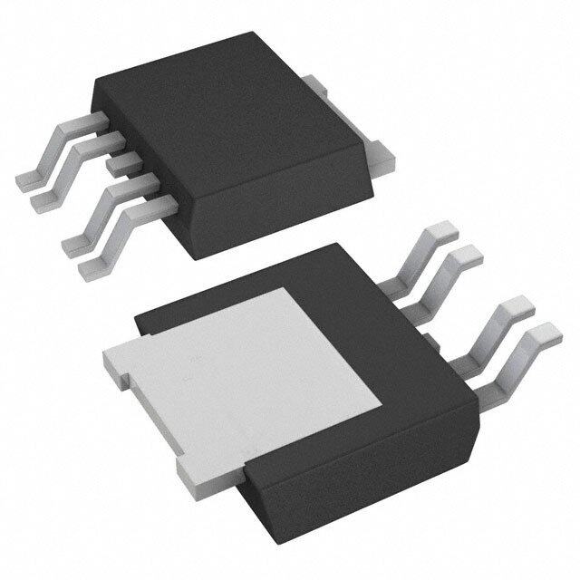
ICGOO电子元器件商城为您提供TPS7A1601DRBT由Texas Instruments设计生产,在icgoo商城现货销售,并且可以通过原厂、代理商等渠道进行代购。 TPS7A1601DRBT价格参考。Texas InstrumentsTPS7A1601DRBT封装/规格:PMIC - 稳压器 - 线性, Linear Voltage Regulator IC Positive Adjustable 1 Output 1.2 V ~ 18.5 V 100mA 8-SON (3x3)。您可以下载TPS7A1601DRBT参考资料、Datasheet数据手册功能说明书,资料中有TPS7A1601DRBT 详细功能的应用电路图电压和使用方法及教程。
TPS7A1601DRBT 是 Texas Instruments(德州仪器)推出的一款高性能、低噪声线性稳压器,属于 PMIC(电源管理集成电路)系列中的线性稳压器类别。其主要应用场景包括:

1. 精密模拟电路供电
   TPS7A1601DRBT 具有极低的输出噪声(典型值为 3 µVrms),非常适合为对电源噪声敏感的精密模拟电路供电,例如高精度数据转换器(ADC/DAC)、传感器接口和射频前端模块等。

2. 通信设备
   在无线通信系统中,如基站、路由器或物联网设备,该器件可为低噪声要求的射频(RF)电路提供稳定电源,确保信号质量和通信性能。

3. 医疗电子设备
   医疗设备(如便携式超声波设备、心率监测仪或血糖仪)需要高度可靠的低噪声电源。TPS7A1601DRBT 的高 PSRR(电源抑制比)特性能够有效抑制电源干扰,保证设备的测量精度和稳定性。

4. 工业自动化与控制
   在工业环境中,TPS7A1601DRBT 可用于为微控制器、FPGA 或 DSP 提供干净的电源,支持精确的数据处理和控制系统运行。

5. 消费类电子产品
   高端音频设备、摄像头模组和便携式电子设备可以利用 TPS7A1601DRBT 的低噪声特性,提升音质或图像质量,同时延长电池寿命。

6. 汽车电子系统
   虽然 TPS7A1601DRBT 不是专门针对汽车应用设计,但其优异的性能也可用于非关键车载系统,如信息娱乐系统或传感器模块。

总结来说,TPS7A1601DRBT 凭借其低噪声、高 PSRR 和宽输入电压范围(1.8V 至 5.5V)的特点,适用于需要高精度、低干扰电源的各种场景,特别是在通信、医疗、工业和消费类领域中表现突出。
| 参数 | 数值 |
| 产品目录 | 集成电路 (IC)半导体 |
| 描述 | IC REG LDO ADJ 0.1A 8SON低压差稳压器 60V 5uA Iq 100mA LDO VTG Reg |
| DevelopmentKit | TPS7A1601EVM-046 |
| 产品分类 | |
| 品牌 | Texas Instruments |
| 产品手册 | |
| 产品图片 | |
| rohs | 符合RoHS无铅 / 符合限制有害物质指令(RoHS)规范要求 |
| 产品系列 | 电源管理 IC,低压差稳压器,Texas Instruments TPS7A1601DRBT- |
| 数据手册 | |
| 产品型号 | TPS7A1601DRBT |
| PSRR/纹波抑制—典型值 | 50 dB |
| 产品 | LDO Regulators |
| 产品种类 | 低压差稳压器 |
| 供应商器件封装 | 8-SON(3x3) |
| 其它名称 | 296-37088-1 |
| 制造商产品页 | http://www.ti.com/general/docs/suppproductinfo.tsp?distId=10&orderablePartNumber=TPS7A1601DRBT |
| 包装 | 剪切带 (CT) |
| 商标 | Texas Instruments |
| 回动电压—最大值 | 500 mV |
| 安装类型 | 表面贴装 |
| 安装风格 | SMD/SMT |
| 封装 | Reel |
| 封装/外壳 | 8-VDFN 裸露焊盘 |
| 封装/箱体 | VSON-8 |
| 工作温度 | -40°C ~ 125°C |
| 工厂包装数量 | 250 |
| 最大工作温度 | + 125 C |
| 最大输入电压 | 60 V |
| 最小工作温度 | - 40 C |
| 最小输入电压 | 3 V |
| 标准包装 | 1 |
| 电压-跌落(典型值) | 0.265V @ 100mA |
| 电压-输入 | 3 V ~ 60 V |
| 电压-输出 | 1.2 V ~ 18.5 V |
| 电压调节准确度 | 2 % |
| 电流-输出 | 100mA |
| 电流-限制(最小值) | 101mA |
| 电源电流 | 5 uA |
| 稳压器拓扑 | 正,可调式 |
| 稳压器数 | 1 |
| 类型 | Low Dropout Voltage Regulator |
| 系列 | TPS7A1601 |
| 线路调整率 | 1 % |
| 负载调节 | 1 % |
| 输出电压 | 1.2 V to 18.5 V |
| 输出电流 | 100 mA |
| 输出端数量 | 1 Output |
| 输出类型 | Adjustable |


- 商务部:美国ITC正式对集成电路等产品启动337调查
- 曝三星4nm工艺存在良率问题 高通将骁龙8 Gen1或转产台积电
- 太阳诱电将投资9.5亿元在常州建新厂生产MLCC 预计2023年完工
- 英特尔发布欧洲新工厂建设计划 深化IDM 2.0 战略
- 台积电先进制程称霸业界 有大客户加持明年业绩稳了
- 达到5530亿美元!SIA预计今年全球半导体销售额将创下新高
- 英特尔拟将自动驾驶子公司Mobileye上市 估值或超500亿美元
- 三星加码芯片和SET,合并消费电子和移动部门,撤换高东真等 CEO
- 三星电子宣布重大人事变动 还合并消费电子和移动部门
- 海关总署:前11个月进口集成电路产品价值2.52万亿元 增长14.8%


PDF Datasheet 数据手册内容提取
Product Sample & Technical Tools & Support & Reference Folder Buy Documents Software Community Design TPS7A16 SBVS171F–DECEMBER2011–REVISEDOCTOBER2015 TPS7A16 60-V, 5-µA I , 100-mA, Low-Dropout Voltage Regulator Q With Enable and Power-Good 1 Features 3 Description • WideInputVoltageRange:3Vto60V The TPS7A16 family of ultralow power, low-dropout 1 (LDO) voltage regulators offers the benefits of ultra- • UltralowQuiescentCurrent:5 µA low quiescent current, high input voltage and • QuiescentCurrentatShutdown:1 µA miniaturized,highthermal-performancepackaging. • OutputCurrent:100mA The TPS7A16 family is designed for continuous or • LowDropoutVoltage:60mVat20mA sporadic (power backup) battery-powered • Accuracy:2% applications where ultralow quiescent current is criticaltoextendingsystembatterylife. • Availablein: – FixedOutputVoltage:3.3V,5V The TPS7A16 family offers an enable pin (EN) compatible with standard CMOS logic and an – AdjustableVersionfrom1.2Vto18.5V integrated open drain active-high power good output • Power-GoodWithProgrammableDelay (PG)withauser-programmabledelay.Thesepinsare • CurrentLimitandThermalShutdownProtections intended for use in microcontroller-based, battery- powered applications where power-rail sequencing is • StablewithCeramicOutputCapacitors: required. ≥2.2 µF In addition, the TPS7A16 is ideal for generating a • Packages:HighThermalPerformanceMSOP-8 low-voltage supply from multicell solutions ranging andSON-8PowerPAD™ from high cell-count power-tool packs to automotive • OperatingTemperatureRange: applications; not only can this device supply a well- –40°Cto125°C regulated voltage rail, but it can also withstand and maintain regulation during voltage transients. These 2 Applications features translate to simpler and more cost-effective, electricalsurge-protectioncircuitry. • PowerSuppliesforNotebookPCs,DigitalTVs, andPrivateLANSystems DeviceInformation(1) • HighCell-CountBatteryPacksforPowerTools PARTNUMBER PACKAGE BODYSIZE(NOM) andotherBattery-PoweredMicroprocessorand HVSSOP(8) 3.00mm×3.00mm MicrocontrollerSystems TPS7A16 VSON(8) 3.00mm×3.00mm • CarAudio,Navigation,Infotainment,andOther AutomotiveSystems (1) Forallavailablepackages,seethepackageoptionaddendum attheendofthedatasheet. • SmokeandCO DetectorsandBattery-Powered 2 AlarmandSecuritySystems TypicalApplicationSchematic QuiescentCurrentvsInputVoltage VIN 50 60 V IOUT = 0mA − 40°C + 25°C 12 V t 40 + 85°C + 105°C VIN IN OUT VOUT VCC µC2 + 125°C CIN COUT EN 30 VEN EN TPS7A16 RPG (µA)Q I 20 CDELAY DELAY GND PG VPG IO1 µC1 IO3 IO2 10 0 0 10 20 30 40 50 60 Input Voltage (V) 1 An IMPORTANT NOTICE at the end of this data sheet addresses availability, warranty, changes, use in safety-critical applications, intellectualpropertymattersandotherimportantdisclaimers.PRODUCTIONDATA.
TPS7A16 SBVS171F–DECEMBER2011–REVISEDOCTOBER2015 www.ti.com Table of Contents 1 Features.................................................................. 1 8 ApplicationandImplementation........................ 13 2 Applications........................................................... 1 8.1 ApplicationInformation............................................13 3 Description............................................................. 1 8.2 TypicalApplications................................................13 4 RevisionHistory..................................................... 2 9 PowerSupplyRecommendations...................... 19 5 PinConfigurationandFunctions......................... 4 10 Layout................................................................... 19 6 Specifications......................................................... 5 10.1 LayoutGuidelines.................................................19 6.1 AbsoluteMaximumRatings .....................................5 10.2 LayoutExample....................................................19 6.2 ESDRatings..............................................................5 10.3 PowerDissipation.................................................21 6.3 RecommendedOperatingConditions.......................5 10.4 ThermalConsiderations........................................21 6.4 ThermalInformation..................................................6 11 DeviceandDocumentationSupport................. 22 6.5 ElectricalCharacteristics...........................................6 11.1 DocumentationSupport........................................22 6.6 TypicalCharacteristics..............................................7 11.2 CommunityResources..........................................22 7 DetailedDescription............................................ 10 11.3 Trademarks...........................................................22 7.1 Overview.................................................................10 11.4 ElectrostaticDischargeCaution............................22 7.2 FunctionalBlockDiagram.......................................10 11.5 Glossary................................................................22 7.3 FeatureDescription.................................................11 12 Mechanical,Packaging,andOrderable Information........................................................... 22 7.4 DeviceFunctionalModes........................................12 4 Revision History NOTE:Pagenumbersforpreviousrevisionsmaydifferfrompagenumbersinthecurrentversion. ChangesfromRevisionE(August2015)toRevisionF Page • Changedψ valueinThermalInformationtablefrom141.2to11.2(typo) ......................................................................... 6 JB ChangesfromRevisionD(January2014)toRevisionE Page • AddedESDRatingstable,FeatureDescriptionsection,DeviceFunctionalModes,ApplicationandImplementation section,PowerSupplyRecommendationssection,Layoutsection,DeviceandDocumentationSupportsection,and Mechanical,Packaging,andOrderableInformationsection ................................................................................................. 1 • ChangedMINvalueofRegulatedoutputfrom1.2to1.169 .................................................................................................. 5 • ChangedMAXvalueofRegulatedoutputfrom18to18.5 ................................................................................................... 5 • ChangedMAXvalueofOperatingjunctiontemperaturefrom150to125 ............................................................................ 5 • ChangedvalueinPower-Goodsectionfrom5.5-Vto5-V................................................................................................... 11 ChangesfromRevisionC(November2013)toRevisionD Page • ChangedFeedbackCurrentmin,typ,andmaxvaluesfrom–1.0,0.0,and1.0to–0.1,–0.01,and0.1,respectively..........6 • ChangedEnableCurrenttypvaluefrom0.01to–0.01.......................................................................................................... 6 ChangesfromRevisionB(April2013)toRevisionC Page • ChangedDRBpackagefromproductpreviewtoproductiondata......................................................................................... 1 • AddedDRBpackagetothermalinformation.......................................................................................................................... 6 • ChangedFigure4Y-axisunitfromVtomV(typo)................................................................................................................ 7 ChangesfromRevisionA(December2011)toRevisionB Page • AddedpreviewDRBpackagetodatasheet........................................................................................................................... 1 2 SubmitDocumentationFeedback Copyright©2011–2015,TexasInstrumentsIncorporated ProductFolderLinks:TPS7A16
TPS7A16 www.ti.com SBVS171F–DECEMBER2011–REVISEDOCTOBER2015 ChangesfromOriginal(December2011)toRevisionA Page • Changeddatasheettofromproductpreviewtoproductiondata.......................................................................................... 1 Copyright©2011–2015,TexasInstrumentsIncorporated SubmitDocumentationFeedback 3 ProductFolderLinks:TPS7A16
TPS7A16 SBVS171F–DECEMBER2011–REVISEDOCTOBER2015 www.ti.com 5 Pin Configuration and Functions DGNPackage 8-PinHVSSOP DRBPackage TopView 8-PinVSON TopView OUT 1 8 IN OUT 1 8 IN FB/DNC 2 7 DELAY FB/DNC 2 7 DELAY PG 3 6 NC GND PG 3 6 NC GND 4 5 EN GND 4 5 EN PinFunctions PIN I/O DESCRIPTION NAME NO. Delaypin.ConnectacapacitortoGNDtoadjustthePGdelaytime;leaveopeniftheresetfunctionis DELAY 7 O notneeded. Enablepin.Thispinturnstheregulatoronoroff. IfV ≥V ,theregulatorisenabled. EN 5 I EN EN_HI IfV ≤V ,theregulatorisdisabled. EN EN_LO Ifnotused,theENpincanbeconnectedtoIN.MakesurethatV ≤V atalltimes. EN IN Fortheadjustableversion(TPS7A1601),thefeedbackpinistheinputtothecontrol-looperror amplifier.Thispinisusedtosettheoutputvoltageofthedevicewhentheregulatoroutputvoltageis FB/DNC 2 I setbyexternalresistors. Forthefixedvoltageversions:Donotconnecttothispin.Donotroutethispintoanyelectricalnet, notevenGNDorIN. GND 4 GND Groundpin. Regulatorinputsupplypin.Acapacitor≥0.1µFmustbetiedfromthispintogroundtoassurestability. TIrecommendsconnectinga10-µFceramiccapacitorfromINtoGND(asclosetothedeviceas IN 8 IN possible)toreducecircuitsensitivitytoprinted-circuit-board(PCB)layout,especiallywhenlonginput tracesorhighsourceimpedancesareencountered. NC 6 — ThispincanbeleftopenortiedtoanyvoltagebetweenGNDandIN. Regulatoroutputpin.Acapacitor≥2.2µFmustbetiedfromthispintogroundtoassurestability.TI OUT 1 O recommendsconnectinga10-µFceramiccapacitorfromOUTtoGND(asclosetothedeviceas possible)tomaximizeACperformance. Power-goodpin.Opencollectoroutput;leaveopenorconnecttoGNDifthepower-goodfunctionis PG 3 O notneeded. Soldertoprinted-circuit-board(PCB)toenhancethermalperformance.Althoughitcanbeleftfloating, PowerPAD — — TIhighlyrecommendsconnectingthePowerPADtotheGNDplane. 4 SubmitDocumentationFeedback Copyright©2011–2015,TexasInstrumentsIncorporated ProductFolderLinks:TPS7A16
TPS7A16 www.ti.com SBVS171F–DECEMBER2011–REVISEDOCTOBER2015 6 Specifications 6.1 Absolute Maximum Ratings Overoperatingfree-airtemperaturerange–40°C≤T ≤125°C(unlessotherwisenoted).(1) J MIN MAX UNIT INpintoGNDpin –0.3 62 OUTpintoGNDpin –0.3 20 OUTpintoINpin –62 0.3 FBpintoGNDpin –0.3 3 Voltage FBpintoINpin –62 0.3 V ENpintoINpin –62 0.3 ENpintoGNDpin –0.3 62 PGpintoGNDpin –0.3 5.5 DELAYpintoGNDpin –0.3 5.5 Current Peakoutput Internallylimited Operatingvirtualjunction,T –40 150 J Temperature °C Storage,T –65 150 stg (1) StressesbeyondthoselistedunderAbsoluteMaximumRatingsmaycausepermanentdamagetothedevice.Thesearestressratings only,whichdonotimplyfunctionaloperationofthedeviceattheseoranyotherconditionsbeyondthoseindicatedunderRecommended OperatingConditions.Exposuretoabsolute-maximum-ratedconditionsforextendedperiodsmayaffectdevicereliability. 6.2 ESD Ratings VALUE UNIT Humanbodymodel(HBM),perANSI/ESDA/JEDECJS-001,allpins(1) ±2000 V(ESD) Electrostaticdischarge Chargeddevicemodel(CDM),perJEDECspecificationJESD22-C101,all V pins(2) ±500 (1) JEDECdocumentJEP155statesthat500-VHBMallowssafemanufacturingwithastandardESDcontrolprocess. (2) JEDECdocumentJEP157statesthat250-VCDMallowssafemanufacturingwithastandardESDcontrolprocess. 6.3 Recommended Operating Conditions overoperatingfree-airtemperaturerange(unlessotherwisenoted) MIN NOM MAX UNIT V Unregulatedinput 3 60 V IN V Regulatedoutput 1.169 18.5 V OUT EN 0 40 V DELAY 0 5 V PG 0 5 V T Operatingjunctiontemperaturerange –40 125 °C J Copyright©2011–2015,TexasInstrumentsIncorporated SubmitDocumentationFeedback 5 ProductFolderLinks:TPS7A16
TPS7A16 SBVS171F–DECEMBER2011–REVISEDOCTOBER2015 www.ti.com 6.4 Thermal Information TPS7A1601 THERMALMETRIC(1) DGN(HVSSOP) DRB(VSON) UNIT 8PINS 8PINS R Junction-to-ambientthermalresistance 66.2 44.5 °C/W θJA R Junction-to-case(top)thermalresistance 45.9 49.5 °C/W θJC(top) R Junction-to-boardthermalresistance 34.6 11.3 °C/W θJB ψ Junction-to-topcharacterizationparameter 1.9 0.7 °C/W JT ψ Junction-to-boardcharacterizationparameter 34.3 11.2 °C/W JB R Junction-to-case(bottom)thermalresistance 14.9 4.7 °C/W θJC(bot) (1) Formoreinformationabouttraditionalandnewthermalmetrics,seetheSemiconductorandICPackageThermalMetricsapplication report,SPRA953. 6.5 Electrical Characteristics AtT =–40°Cto125°C,V =V +0.5VorV =3V(whicheverisgreater),V =V ,I =10µA,C =1μF,C =2.2μF,and J IN OUT(NOM) IN EN IN OUT IN OUT FBtiedtoOUT,unlessotherwisenoted. PARAMETER TESTCONDITIONS MIN TYP MAX UNIT V Inputvoltagerange 3 60 V IN V Internalreference T =25°C,V =V ,V =3V,I =10μA 1.169 1.193 1.217 V REF J FB REF IN OUT V Undervoltagelockoutthreshold 2.7 V UVLO Outputvoltagerange V ≥V +0.5V V 18.5 V IN OUT(NOM) REF Nominalaccuracy T =25°C,V =3V,I =10μA –2% 2% V V J IN OUT OUT OUT V +0.5V≤V ≤60V(1) Overallaccuracy OUT(NOM) IN –2% 2% V 10µA≤I ≤100mA OUT OUT ΔV Lineregulation 3V≤V ≤60V ±1% V O(ΔVI) IN OUT ΔV Loadregulation 10µA≤I ≤100mA ±1% V O(ΔIO) OUT OUT V =4.5V,V =5V,I =20mA 60 mV IN OUT(NOM) OUT V Dropoutvoltage DO V =4.5V,V =5V,I =100mA 265 500 mV IN OUT(NOM) OUT I Currentlimit V =90%V ,V =3V 101 225 400 mA LIM OUT OUT(NOM) IN 3V≤V ≤60V,I =10µA 5 15 μA IN OUT I Groundcurrent GND I =100mA 5 μA OUT I Shutdownsupplycurrent V =0.4V 0.59 5 μA SHDN EN I Feedbackcurrent(2) –0.1 –0.01 0.1 µA FB I Enablecurrent 3V≤V ≤12V,V =V –1 –0.01 1 μA EN IN IN EN V Enablehigh-levelvoltage 1.2 V EN_HI V Enablelow-levelvoltage 0.3 V EN_LO OUTpinfloating,V increasing,V ≥V 85% 95% V FB IN IN_MIN OUT V PGtripthreshold IT OUTpinfloating,V decreasing,V ≥V 83% 93% V FB IN IN_MIN OUT V PGtriphysteresis 2.3% 4% V HYS OUT V PGoutputlowvoltage OUTpinfloating,V =80%V ,I =1mA 0.4 V PG,LO FB REF PG I PGleakagecurrent V =V –1 1 μA PG,LKG PG OUT(NOM) I DELAYpincurrent 1 2 μA DELAY V =3V,V =V ,C =10μF, PSRR Power-supplyrejectionratio IN OUT(NOM) REF OUT 50 dB f=100Hz Shutdown,temperatureincreasing 170 °C T Thermalshutdowntemperature SD Reset,temperaturedecreasing 150 °C Operatingjunctiontemperature T –40 125 °C J range (1) Maximuminputvoltageislimitedto24Vbecauseofthepackagepowerdissipationlimitationsatfullload(P≈(V –V )×I = IN OUT OUT (24V–V )×50mA≈1.14W).Thedeviceiscapableofsourcingamaximumcurrentof50mAathigherinputvoltagesaslongas REF thepowerdissipatediswithinthethermallimitsofthepackageplusanyexternalheatsinking. (2) I >0flowsoutofthedevice. FB 6 SubmitDocumentationFeedback Copyright©2011–2015,TexasInstrumentsIncorporated ProductFolderLinks:TPS7A16
TPS7A16 www.ti.com SBVS171F–DECEMBER2011–REVISEDOCTOBER2015 6.6 Typical Characteristics AtT =–40°Cto125°C,V =V +0.5VorV =3V(whicheverisgreater),V =V ,I =10µA,C =1μF,C J IN OUT(NOM) IN EN IN OUT IN OUT =2.2μF,andFBtiedtoOUT,unlessotherwisenoted. 50 10 IOUT = 0mA − 40°C 9 VEN = 0.4V − 40°C + 25°C + 25°C 40 + 85°C 8 + 85°C + 105°C + 105°C + 125°C 7 + 125°C 30 6 A) A) µ µ 5 (Q (Q I 20 I 4 3 10 2 1 0 0 0 10 20 30 40 50 60 0 10 20 30 40 50 60 Input Voltage (V) Input Voltage (V) Figure1.QuiescentCurrentvsInputVoltage Figure2.ShutdownCurrentvsInputVoltage 100 1000 − 40°C −40°C + 105°C 90 + 25°C 900 + 25°C + 125°C 80 + 85°C 800 + 85°C + 105°C 70 + 125°C 700 A) 60 mV) 600 (µD 50 (OP 500 IGN 40 VDR 400 30 300 20 200 10 100 0 0 0 10 20 30 40 50 60 70 80 90 100 0 20 40 60 80 100 Output Current (mA) Output Current (mA) Figure3.GroundCurrentvsOutputCurrent Figure4.DropoutVoltagevsOutputCurrent 1.294 10 − 40°C + 105°C − 40°C + 105°C + 25°C + 125°C 7.5 + 25°C + 125°C + 85°C + 85°C 1.244 5 %) 2.5 V (V)FB1.194 (()UTNOM 0 O−2.5 V 1.144 −5 −7.5 1.094 −10 0 10 20 30 40 50 60 0 10 20 30 40 50 60 Input Voltage (V) Input Voltage (V) Figure5.FeedbackVoltagevsInputVoltage Figure6.LineRegulation Copyright©2011–2015,TexasInstrumentsIncorporated SubmitDocumentationFeedback 7 ProductFolderLinks:TPS7A16
TPS7A16 SBVS171F–DECEMBER2011–REVISEDOCTOBER2015 www.ti.com Typical Characteristics (continued) AtT =–40°Cto125°C,V =V +0.5VorV =3V(whicheverisgreater),V =V ,I =10µA,C =1μF,C J IN OUT(NOM) IN EN IN OUT IN OUT =2.2μF,andFBtiedtoOUT,unlessotherwisenoted. 10 300 − 40°C + 105°C 7.5 + 25°C + 125°C + 85°C 250 5 200 %) 2.5 (()OUTNOM−2.50 I (mA)CL150 V 100 − 40°C −5 + 25°C 50 + 85°C −7.5 + 105°C + 125°C −10 0 0 10 20 30 40 50 60 70 80 90 100 0 2 4 6 8 10 12 Output Current (mA) Input Voltage (V) Figure7.LoadRegulation Figure8.CurrentLimitvsInputVoltage 95 2.5 93 2 PG Rising %) 91 1.5 (OUTNOM 89 V (V)EN 1 OFF−TO−ON V 87 0.5 PG Falling ON−TO−OFF 85 0 −40 −25 −10 5 20 35 50 65 80 95 110 125 −40 −25 −10 5 20 35 50 65 80 95 110 125 Temperature (°C) Temperature (°C) Figure9.Power-GoodThresholdVoltagevsTemperature Figure10.EnableThresholdVoltagevsTemperature 100 10 90 80 1 70 z) B) 60 H R (d 50 V/ 0.1 PSR 40 moise ( N 30 0.01 20 VIN = 3V VIN = 3V 10 VCOOUUTT == ~110.m2FV VCOOUUTT == 12..22Vm F 0 0.001 10 100 1k 10k 100k 10 100 1k 10k 100k 1M 10M Frequency (Hz) Frequency (Hz) Figure11.Power-SupplyRejectionRatio Figure12.OutputSpectralNoiseDensity 8 SubmitDocumentationFeedback Copyright©2011–2015,TexasInstrumentsIncorporated ProductFolderLinks:TPS7A16
TPS7A16 www.ti.com SBVS171F–DECEMBER2011–REVISEDOCTOBER2015 Typical Characteristics (continued) AtT =–40°Cto125°C,V =V +0.5VorV =3V(whicheverisgreater),V =V ,I =10µA,C =1μF,C J IN OUT(NOM) IN EN IN OUT IN OUT =2.2μF,andFBtiedtoOUT,unlessotherwisenoted. V (2 V/div) IN V (2 V/div) PG V = 1 V®6.5 V IN I = 1 mA V (1 V/div) OUT OUT C = 10mF OUT C = 0 nF FF Time (5 ms/div) Figure13.Power-GoodDelay Copyright©2011–2015,TexasInstrumentsIncorporated SubmitDocumentationFeedback 9 ProductFolderLinks:TPS7A16
TPS7A16 SBVS171F–DECEMBER2011–REVISEDOCTOBER2015 www.ti.com 7 Detailed Description 7.1 Overview The TPS7A16 family of devices are ultralow power, low-dropout (LDO) voltage regulators that offer the benefits of ultralow quiescent current, high input voltage, and miniaturized, high thermal-performance packaging. The TPS7A16 family also offers an enable pin (EN) and integrated open-drain active-high power-good output (PG) withauser-programmabledelay. 7.2 Functional Block Diagram IN OUT UVLO Pass Device Thermal Shutdown Current Limit Error Enable Amp FB EN PG Power Good Control DELAY 10 SubmitDocumentationFeedback Copyright©2011–2015,TexasInstrumentsIncorporated ProductFolderLinks:TPS7A16
TPS7A16 www.ti.com SBVS171F–DECEMBER2011–REVISEDOCTOBER2015 7.3 Feature Description 7.3.1 Enable(EN) The enable terminal is a high-voltage-tolerant terminal. A high input on EN actives the device and turns on the regulator.Forself-biasapplications,connectthisinputtotheV terminal. IN 7.3.2 RegulatedOutput(V ) OUT TheV terminalistheregulatedoutputbasedontherequiredvoltage.Theoutputhascurrentlimitation.During OUT initial power up, the regulator has a soft start incorporated to control the initial current through the pass element. In the event that the regulator drops out of regulation, the output tracks the input minus a drop based on the load current.WhentheinputvoltagedropsbelowtheUVLOthreshold,theregulatorshutsdownuntiltheinputvoltage recoversabovetheminimumstart-uplevel. 7.3.3 Power-Good The power-good (PG) pin is an open-drain output and can be connected to any 5-V or lower rail through an external pull-up resistor. When no C is used, the PG output is high-impedance when V is greater than DELAY OUT thePGtripthreshold(V ).IfV dropsbelowV ,theopen-drainoutputturnsonandpullsthePGoutputlow.If IT OUT IT outputvoltagemonitoringisnotneeded,thePGpincanbeleftfloatingorconnectedtoGND. Thepower-goodfeaturefunctionalityisonlyguaranteedwhenV ≥3V(V ) IN IN_(MIN) 7.3.4 PGDelayTimer(DELAY) The power-good delay time (t ) is defined as the time period from when V exceeds the PG trip threshold DELAY OUT voltage (V ) to when the PG output is high. This power-good delay time is set by an external capacitor (C ) IT DELAY connected from the DELAY pin to GND; this capacitor is charged from 0 V to approximately 1.8 V by the DELAY pincurrent(I )onceV exceedsthePGtripthreshold(V ). DELAY OUT IT WhenC isused,thePGoutputishigh-impedancewhenV exceedsV ,andV exceedsV . DELAY OUT IT DELAY REF The power-good delay time can be calculated using: t = (C × V ) / I . For example, when C DELAY DELAY REF DELAY DELAY =10nF,thePGdelaytimeisapproximately12ms;thatis,(10nF ×1.193V)/1 µA=11.93ms. 7.3.5 InternalCurrentLimit The fixed internal current limit of the TPS7A16 family helps protect the regulator during fault conditions. The maximum amount of current the device can source is the current limit (225 mA, typical), and is largely independent of output voltage. For reliable operation, do not operate the device in current limit for extended periodsoftime. 7.3.6 ThermalProtection Thermal protection disables the output when the junction temperature rises to approximately 170°C, allowing the device to cool. When the junction temperature cools to approximately 150°C, the output circuitry is enabled. Depending on power dissipation, thermal resistance, and ambient temperature, the thermal protection circuit may cycle ON and OFF. This cycling limits the dissipation of the regulator, protecting it from damage as a result of overheating. Copyright©2011–2015,TexasInstrumentsIncorporated SubmitDocumentationFeedback 11 ProductFolderLinks:TPS7A16
TPS7A16 SBVS171F–DECEMBER2011–REVISEDOCTOBER2015 www.ti.com 7.4 Device Functional Modes 7.4.1 NormalOperation Thedeviceregulatestothenominaloutputvoltageunderthefollowingconditions: • TheinputvoltageisatleastashighasV . IN(MIN) • Theinputvoltageisgreaterthanthenominaloutputvoltageaddedtothedropoutvoltage. • The enable voltage has previously exceeded the enable rising threshold voltage and has not decreased belowtheenablefallingthreshold. • Theoutputcurrentislessthanthecurrentlimit. • Thedevicejunctiontemperatureislessthanthemaximumspecifiedjunctiontemperature. 7.4.2 DropoutOperation If the input voltage is lower than the nominal output voltage plus the specified dropout voltage, but all other conditions are met for normal operation, the device operates in dropout mode. In this mode of operation, the output voltage is the same as the input voltage minus the dropout voltage. The transient performance of the device is significantly degraded because the pass device (such as a bipolar junction transistor, or BJT) is in saturation and no longer controls the current through the LDO. Line or load transients in dropout can result in largeoutputvoltagedeviations. 7.4.3 Disabled Thedeviceisdisabledunderthefollowingconditions: • The enable voltage is less than the enable falling threshold voltage or has not yet exceeded the enable rising threshold. • Thedevicejunctiontemperatureisgreaterthanthethermalshutdowntemperature. Table1liststheconditionsthatleadtothedifferentmodesofoperation. Table1.DeviceFunctionalModeComparison PARAMETER OPERATINGMODE V V I T IN EN OUT J V >V +V Normalmode IN OUT(NOM) DO V >V I <I T <125°C andV >V EN EN_HI OUT LIM J IN IN(MIN) Dropoutmode V <V +V V >V — T <125°C IN OUT(NOM) DO EN EN_HI J Disabledmode(anytrue conditiondisablesthe — V <V — T >170°C EN EN_HI J device 12 SubmitDocumentationFeedback Copyright©2011–2015,TexasInstrumentsIncorporated ProductFolderLinks:TPS7A16
TPS7A16 www.ti.com SBVS171F–DECEMBER2011–REVISEDOCTOBER2015 8 Application and Implementation NOTE Information in the following applications sections is not part of the TI component specification, and TI does not warrant its accuracy or completeness. TI’s customers are responsible for determining suitability of components for their purposes. Customers should validateandtesttheirdesignimplementationtoconfirmsystemfunctionality. 8.1 Application Information The TPS7A16 family of ultralow power voltage regulators offers the benefit of ultralow quiescent current, high inputvoltage,andminiaturized,highthermal-performancepackaging. The TPS7A16 family is designed for continuous or sporadic (power backup) battery-operated applications where ultralowquiescentcurrentiscriticaltoextendingsystembatterylife. 8.2 Typical Applications 8.2.1 TPS7A1601CircuitasanAdjustableRegulator VIN IN OUT VOUT C C IN C R OUT FF 1 V VEN EN TPS7A1601 FB RPG Where: R1= R2 VOUT -1 REF R 2 DELAY GND PG VPG C DELAY Figure14. TPS7A1601CircuitasanAdjustableRegulatorSchematic 8.2.1.1 DesignRequirements Table2liststhedesignparameters. Table2.DesignParameters DESIGNPARAMETER EXAMPLEVALUE Inputvoltagerange 5.5Vto40V Outputvoltage 5V Outputcurrentrating 100mA Outputcapacitorrange 2.2μFto100μF Delaycapacitorrange 100pFto100nF 8.2.1.2 DetailedDesignProcedure 8.2.1.2.1 AdjustableVoltageOperation The TPS7A1601 has an output voltage range from 1.194 V to 20 V. The nominal output of the device is set by twoexternalresistors,asshowninFigure15: Copyright©2011–2015,TexasInstrumentsIncorporated SubmitDocumentationFeedback 13 ProductFolderLinks:TPS7A16
TPS7A16 SBVS171F–DECEMBER2011–REVISEDOCTOBER2015 www.ti.com VIN IN PG C R IN PG 0.1mF 1 MW V EN OUT OUT C 5 V R OUT 1 2.2mF 3.4 MW DELAY C FB DELAY 0.1mF R 2 GND 1.07 MW Figure15. AdjustableOperation R andR canbecalculatedforanyoutputvoltagerangeusingtheformulashowninEquation1: 1 2 V R = R OUT -1 1 2 V REF (1) 8.2.1.2.1.1 ResistorSelection TI recommends using resistors in the order of MΩ to keep the overall quiescent current of the system as low as possible (by making the current used by the resistor divider negligible compared to the device’s quiescent current). If greater voltage accuracy is required, consider the voltage offset contributions as a result of feedback current anduseof0.1%toleranceresistors. Table 3 shows the resistor combination to achieve a few of the most common rails using commercially available 0.1% tolerance resistors to maximize nominal voltage accuracy, while abiding to the formula shown in Equation1. Table3.SelectedResistorCombinations V R R V /(R +R )«I NOMINALACCURACY OUT 1 2 OUT 1 2 Q 1.194V 0Ω ∞ 0µA ±2% 1.8V 1.18MΩ 2.32MΩ 514nA ±(2%+0.14%) 2..5V 1.5MΩ 1.37MΩ 871nA ±(2%+0.16%) 3.3V 2MΩ 1.13MΩ 1056nA ±(2%+0.35%) 5V 3.4MΩ 1.07MΩ 1115nA ±(2%+0.39%) 10V 7.87MΩ 1.07MΩ 1115nA ±(2%+0.42%) 12V 14.3MΩ 1.58MΩ 755nA ±(2%+0.18%) 15V 42.2MΩ 3.65MΩ 327nA ±(2%+0.19%) 18V 16.2MΩ 1.15MΩ 1038nA ±(2%+0.26%) Close attention must be paid to board contamination when using high-value resistors; board contaminants may significantly impact voltage accuracy. If board cleaning measures cannot be ensured, consider using a fixed- voltageversionoftheTPS7A16orusingresistorsintheorderofhundredsortensofkΩ. 8.2.1.2.1.2 CapacitorRecommendations Low equivalent series resistance (ESR) capacitors should be used for the input, output, and feed-forward capacitors. Ceramic capacitors with X7R and X5R dielectrics are preferred. These dielectrics offer more stable characteristics. Ceramic X7R capacitors offer improved overtemperature performance, while ceramic X5R capacitorsarethemostcost-effectiveandareavailableinhighervalues. HighESRcapacitorsmaydegradePSRR. 14 SubmitDocumentationFeedback Copyright©2011–2015,TexasInstrumentsIncorporated ProductFolderLinks:TPS7A16
TPS7A16 www.ti.com SBVS171F–DECEMBER2011–REVISEDOCTOBER2015 8.2.1.2.1.3 InputandOutputCapacitorRequirements The TPS7A16 family of ultralow power, high-voltage linear regulators achieves stability with a minimum input capacitance of 0.1 µF and output capacitance of 2.2 µF; however, TI recommends using 10-µF ceramic capacitorstomaximizeACperformance. 8.2.1.2.1.4 Feed-ForwardCapacitor Although a feed-forward capacitor (C ) from OUT to FB is not needed to achieve stability, TI recommends using FF a0.01-µFfeed-forwardcapacitortomaximizeACperformance. 8.2.1.2.1.5 TransientResponse As with any regulator, increasing the size of the output capacitor reduces overshoot and undershoot magnitude butincreasesthedurationofthetransientresponse. 8.2.1.3 ApplicationCurves Figure16.CH1isVOUT,CH2isPG,CH3isEN,CH4is Figure17.CH1isVOUT,CH2isPG,CH3isEN,CH4is lOUT,VINis12VandReadyBeforeEN lOUT,VINis12VConnectedtoEN Copyright©2011–2015,TexasInstrumentsIncorporated SubmitDocumentationFeedback 15 ProductFolderLinks:TPS7A16
TPS7A16 SBVS171F–DECEMBER2011–REVISEDOCTOBER2015 www.ti.com 8.2.2 AutomotiveApplications The TPS7A16 family maximum input voltage of 60 V makes it ideal for use in automotive applications where high-voltagetransientsarepresent. Events such as load-dump overvoltage (where the battery is disconnected while the alternator is providing current to a load) may cause voltage spikes from 25 V to 60 V. To prevent any damage to sensitive circuitry, localtransientvoltagesuppressorscanbeusedtocapvoltagespikestolower,moremanageablevoltages. The TPS7A16 family can be used to simplify and lower costs in such cases. The TPS7A16 very high voltage range allows this regulator to not only withstand the voltages coming out of these local transient voltage suppressors,butevenreplacethem,thusloweringsystemcostandcomplexity. V IN 60 V 12 V t V OUT VIN IN OUT VCC µC2 C C IN OUT EN VEN EN TPS7A16 RPG DELAY GND PG IO1 V C PG DELAY µC1 IO3 IO2 Figure18. Low-PowerMicrocontrollerRailSequencinginAutomotiveApplicationsSubjectedtoLoad- DumpTransients 8.2.2.1 DesignRequirements Table4liststhedesignparameters. Table4.DesignParameters DESIGNPARAMETER EXAMPLEVALUE Inputvoltagerange 5.5Vto60V Outputvoltage 5V Outputcurrentrating 100mA Outputcapacitorrange 2.2μFto100μF Delaycapacitorrange 100pFto100nF 8.2.2.2 DetailedDesignProcedure SeeCapacitorRecommendationsandInputandOutputCapacitorRequirements. 8.2.2.2.1 DeviceRecommendations The output is 5 V, so choose either the fixed output version TPS7A1650 or the adjustable output version TPS7A1601,andsettheresistordividerappropriately.SeeResistorSelection formoredetails. 8.2.2.3 ApplicationCurves SeeFigure16andFigure17. 16 SubmitDocumentationFeedback Copyright©2011–2015,TexasInstrumentsIncorporated ProductFolderLinks:TPS7A16
TPS7A16 www.ti.com SBVS171F–DECEMBER2011–REVISEDOCTOBER2015 8.2.3 MulticellBatteryPacks Currently, battery packs can employ up to a dozen cells in series that, when fully charged, may have voltages of up to 55 V. Internal circuitry in these battery packs is used to prevent overcurrent and overvoltage conditions that may degrade battery life or even pose a safety risk; this internal circuitry is often managed by a low-power microcontroller,suchasTI’sMSP430. The microcontroller continuously monitors the battery itself, whether the battery is in use or not. Although this microcontroller could be powered by an intermediate voltage taken from the multicell array, this approach unbalances the battery pack itself, degrading its life or adding cost to implement more complex cell balancing topologies. Thebestapproachtopowerthismicrocontrolleristoregulatedownthevoltagefromtheentirearraytodischarge everycellequallyandpreventanybalancingissues.Thisapproachreducessystemcomplexityandcost. TPS7A16 is the ideal regulator for this application because it can handle very high voltages (from the entire multicellarray)andhasverylowquiescentcurrent(tomaximizebatterylife). UpTo 42 V Sensing + Comparator Cell TPS7A16 Balance Voltage Microcontroller Sensing UART - Figure19. ProtectionBasedonLow-PowerMicrocontrollerPowerfromMulticellBatteryPacks 8.2.3.1 DesignRequirements Table5liststhedesignparameters. Table5.DeviceParameters DESIGNPARAMETER EXAMPLEVALUE Inputvoltagerange 5.5Vto55V Outputvoltage 5V Outputcurrentrating 100mA Outputcapacitorrange 2.2μFto100μF Delaycapacitorrange 100pFto100nF 8.2.3.2 DetailedDesignProcedure SeeDeviceRecommendations,CapacitorRecommendations,andInputandOutputCapacitorRequirements. 8.2.3.3 ApplicationCurves SeeFigure16andFigure17. Copyright©2011–2015,TexasInstrumentsIncorporated SubmitDocumentationFeedback 17 ProductFolderLinks:TPS7A16
TPS7A16 SBVS171F–DECEMBER2011–REVISEDOCTOBER2015 www.ti.com 8.2.4 Battery-OperatedPowerTools High voltage multicell battery packs support high-power applications, such as power tools, with high current drain wheninuse,highlyintermittentusecycles,andphysicalseparationbetweenbatteryandmotor. In these applications, a microcontroller or microprocessor controls the motor. This microcontroller must be powered with a low-voltage rail coming from the high-voltage, multicell battery pack; as mentioned previously, powering this microcontroller or microprocessor from an intermediate voltage from the multicell array causes battery-pack life degradation or added system complexity because of cell balancing issues. In addition, this microcontroller or microprocessor must be protected from the high-voltage transients due to the motor inductance. The TPS7A16 can be used to power the motor-controlled microcontroller or microprocessor; its low quiescent current maximizes battery shelf life and its very high-voltage capabilities simplify system complexity by replacing voltagesuppressionfilters,thusloweringsystemcost. 100W Transient LDO First Optional 0.47mF M Cell Filter Second Cell MSP430 Microcontroller Last PWM Cell Figure20. LowPowerMicrocontrollerPowerFromMulticellBatteryPacksInPowerTools 8.2.4.1 DesignRequirements Table6liststhedesignparameters. Table6.DesignParameters DESIGNPARAMETER EXAMPLEVALUE Inputvoltagerange 5.5Vto60V Outputvoltage 5V Outputcurrentrating 100mA Outputcapacitorrange 2.2μFto100μF Delaycapacitorrange 100pFto100nF 8.2.4.2 DetailedDesignProcedure SeeDeviceRecommendations,CapacitorRecommendations,andInputandOutputCapacitorRequirements. 8.2.4.3 ApplicationCurves SeeFigure16andFigure17. 18 SubmitDocumentationFeedback Copyright©2011–2015,TexasInstrumentsIncorporated ProductFolderLinks:TPS7A16
TPS7A16 www.ti.com SBVS171F–DECEMBER2011–REVISEDOCTOBER2015 9 Power Supply Recommendations The device is designed to operate from an input voltage supply with a range between 3 V and 60 V. This input supply must be well regulated. The TPS7A16 family of ultralow-power, high-voltage linear regulators achieve stability with a minimum input capacitance of 0.1 μF and output capacitance of 2.2 μF; however, TI recommends using10-μFceramiccapacitorstomaximizeacperformance. 10 Layout 10.1 Layout Guidelines To improve AC performance such as PSRR, output noise, and transient response, it is recommended that the board be designed with separate ground planes for IN and OUT, with each ground plane connected only at the GND pin of the device. In addition, the ground connection for the output capacitor should connect directly to the GNDpinofthedevice. Equivalent series inductance (ESL) and ESR must be minimized in order to maximize performance and ensure stability. Every capacitor must be placed as close as possible to the device and on the same side of the PCB as theregulatoritself. DonotplaceanyofthecapacitorsontheoppositesideofthePCBfromwheretheregulatorisinstalled.Theuse of vias and long traces is strongly discouraged because they may impact system performance negatively and evencauseinstability. If possible, and to ensure the maximum performance denoted in this product data sheet, use the same layout patternusedforTPS7A16evaluationboard,availableatwww.ti.com. 10.1.1 AdditionalLayoutConsiderations The high impedance of the FB pin makes the regulator sensitive to parasitic capacitances that may couple undesirable signals from near-by components (specially from logic and digital ICs, such as microcontrollers and microprocessors);thesecapacitively-coupledsignalsmayproduceundesirableoutputvoltagetransients.Inthese cases,TIrecommendsusingafixed-voltageversionoftheTPS7A16,orisolatetheFBnodebyfloodingthelocal PCBareawithground-planecoppertominimizeanyundesirablesignalcoupling. 10.2 Layout Example Layout is a critical part of good power-supply design. There are several signal paths that conduct fast-changing currents or voltages that can interact with stray inductance or parasitic capacitance to generate noise or degrade the power-supply performance. To help eliminate these problems, the IN pin should be bypassed to ground with alowESRceramicbypasscapacitorwithaX5RorX7Rdielectric. It may be possible to obtain acceptable performance with alternative PCB layouts; however, the layout and the schematichavebeenshowntoproducegoodresultsandaremeantasaguideline. Figure 21 shows the schematic for the suggested layout. Figure 22 and Figure 23 show the top and bottom printed-circuit-board(PCB)layersforthesuggestedlayout. Copyright©2011–2015,TexasInstrumentsIncorporated SubmitDocumentationFeedback 19 ProductFolderLinks:TPS7A16
TPS7A16 SBVS171F–DECEMBER2011–REVISEDOCTOBER2015 www.ti.com Layout Example (continued) Input GND Plane Vout Cin Vin OUT 1 8 IN R1 `` Sense Line Cout FB 2 7 DELAY Thermal Pad R2 PG 3 6 NC CDELAY GND 4 5 EN Output GND Plane Notes: Cin and Cout are 1208 packages CNR, R1, and R2 are 0402 packages Denotes a via to a connection made on another layer Figure21. SchematicforSuggestedLayout 1300 mil 2200 mil Figure22. SuggestedLayout:TopLayer 20 SubmitDocumentationFeedback Copyright©2011–2015,TexasInstrumentsIncorporated ProductFolderLinks:TPS7A16
TPS7A16 www.ti.com SBVS171F–DECEMBER2011–REVISEDOCTOBER2015 Layout Example (continued) 1300 mil 2200 mil Figure23. SuggestedLayout:BottomLayer 10.3 Power Dissipation The ability to remove heat from the die is different for each package type, presenting different considerations in the PCB layout. The PCB area around the device that is free of other components moves the heat from the device to the ambient air. Using heavier copper increases the effectiveness in removing heat from the device. Theadditionofplatedthrough-holestoheatdissipatinglayersalsoimprovestheheatsinkeffectiveness. Powerdissipationdependsoninputvoltageandloadconditions.Powerdissipation(P )isequaltotheproductof D theoutputcurrenttimesthevoltagedropacrosstheoutputpasselement,asshowninEquation2: P = (V -V ) I D IN OUT OUT (2) 10.4 Thermal Considerations Any tendency to activate the thermal protection circuit indicates excessive power dissipation or an inadequate heat spreading area. For reliable operation, junction temperature should be limited to a maximum of +125°C at the worst case ambient temperature for a given application. To estimate the margin of safety in a complete design (including the copper heat-spreading area), increase the ambient temperature until the thermal protection is triggered; use worst-case loads and signal conditions. For good reliability, thermal protection should trigger at least +45°C above the maximum expected ambient condition of the particular application. This configuration produces a worst-case junction temperature of +125°C at the highest expected ambient temperature and worst- caseload. The internal protection circuitry of the TPS7A16 has been designed to protect against overload conditions. It was not intended to replace proper heatsinking. Continuously running the TPS7A16 into thermal shutdown degrades devicereliability. Copyright©2011–2015,TexasInstrumentsIncorporated SubmitDocumentationFeedback 21 ProductFolderLinks:TPS7A16
TPS7A16 SBVS171F–DECEMBER2011–REVISEDOCTOBER2015 www.ti.com 11 Device and Documentation Support 11.1 Documentation Support 11.1.1 RelatedDocumentation • ProsandConsofUsingaFeedforwardCapacitorwithaLow-DropoutRegulator,SBVA042 • UsingNewThermalMetrics,SBVA025 11.2 Community Resources The following links connect to TI community resources. Linked contents are provided "AS IS" by the respective contributors. They do not constitute TI specifications and do not necessarily reflect TI's views; see TI's Terms of Use. TIE2E™OnlineCommunity TI'sEngineer-to-Engineer(E2E)Community.Createdtofostercollaboration amongengineers.Ate2e.ti.com,youcanaskquestions,shareknowledge,exploreideasandhelp solveproblemswithfellowengineers. DesignSupport TI'sDesignSupport QuicklyfindhelpfulE2Eforumsalongwithdesignsupporttoolsand contactinformationfortechnicalsupport. 11.3 Trademarks PowerPAD,E2EaretrademarksofTexasInstruments. Allothertrademarksarethepropertyoftheirrespectiveowners. 11.4 Electrostatic Discharge Caution This integrated circuit can be damaged by ESD. Texas Instruments recommends that all integrated circuits be handled with appropriateprecautions.Failuretoobserveproperhandlingandinstallationprocedurescancausedamage. ESDdamagecanrangefromsubtleperformancedegradationtocompletedevicefailure.Precisionintegratedcircuitsmaybemore susceptibletodamagebecauseverysmallparametricchangescouldcausethedevicenottomeetitspublishedspecifications. 11.5 Glossary SLYZ022—TIGlossary. Thisglossarylistsandexplainsterms,acronyms,anddefinitions. 12 Mechanical, Packaging, and Orderable Information The following pages include mechanical, packaging, and orderable information. This information is the most current data available for the designated devices. This data is subject to change without notice and revision of thisdocument.Forbrowser-basedversionsofthisdatasheet,refertotheleft-handnavigation. 22 SubmitDocumentationFeedback Copyright©2011–2015,TexasInstrumentsIncorporated ProductFolderLinks:TPS7A16
PACKAGE OPTION ADDENDUM www.ti.com 30-Sep-2015 PACKAGING INFORMATION Orderable Device Status Package Type Package Pins Package Eco Plan Lead/Ball Finish MSL Peak Temp Op Temp (°C) Device Marking Samples (1) Drawing Qty (2) (6) (3) (4/5) TPS7A1601DGNR ACTIVE MSOP- DGN 8 2500 Green (RoHS CU NIPDAU Level-2-260C-1 YEAR -40 to 125 PTYQ PowerPAD & no Sb/Br) TPS7A1601DGNT ACTIVE MSOP- DGN 8 250 Green (RoHS CU NIPDAU Level-2-260C-1 YEAR -40 to 125 PTYQ PowerPAD & no Sb/Br) TPS7A1601DRBR ACTIVE SON DRB 8 3000 Green (RoHS CU NIPDAU Level-2-260C-1 YEAR -40 to 125 PA5M & no Sb/Br) TPS7A1601DRBT ACTIVE SON DRB 8 250 Green (RoHS CU NIPDAU Level-2-260C-1 YEAR -40 to 125 PA5M & no Sb/Br) TPS7A1633DGNR ACTIVE MSOP- DGN 8 2500 Green (RoHS CU NIPDAU Level-2-260C-1 YEAR -40 to 125 PPNQ PowerPAD & no Sb/Br) TPS7A1633DGNT ACTIVE MSOP- DGN 8 250 Green (RoHS CU NIPDAU Level-2-260C-1 YEAR -40 to 125 PPNQ PowerPAD & no Sb/Br) TPS7A1633DRBR ACTIVE SON DRB 8 3000 Green (RoHS CU NIPDAU Level-2-260C-1 YEAR -40 to 125 PPNQ & no Sb/Br) TPS7A1633DRBT ACTIVE SON DRB 8 250 Green (RoHS CU NIPDAU Level-2-260C-1 YEAR -40 to 125 PPNQ & no Sb/Br) TPS7A1650DGNR ACTIVE MSOP- DGN 8 2500 Green (RoHS CU NIPDAU Level-2-260C-1 YEAR -40 to 125 PPOQ PowerPAD & no Sb/Br) TPS7A1650DGNT ACTIVE MSOP- DGN 8 250 Green (RoHS CU NIPDAU Level-2-260C-1 YEAR -40 to 125 PPOQ PowerPAD & no Sb/Br) TPS7A1650DRBR ACTIVE SON DRB 8 3000 Green (RoHS CU NIPDAU Level-2-260C-1 YEAR -40 to 125 PPOQ & no Sb/Br) TPS7A1650DRBT ACTIVE SON DRB 8 250 Green (RoHS CU NIPDAU Level-2-260C-1 YEAR -40 to 125 PPOQ & no Sb/Br) (1) The marketing status values are defined as follows: ACTIVE: Product device recommended for new designs. LIFEBUY: TI has announced that the device will be discontinued, and a lifetime-buy period is in effect. NRND: Not recommended for new designs. Device is in production to support existing customers, but TI does not recommend using this part in a new design. PREVIEW: Device has been announced but is not in production. Samples may or may not be available. OBSOLETE: TI has discontinued the production of the device. (2) Eco Plan - The planned eco-friendly classification: Pb-Free (RoHS), Pb-Free (RoHS Exempt), or Green (RoHS & no Sb/Br) - please check http://www.ti.com/productcontent for the latest availability information and additional product content details. TBD: The Pb-Free/Green conversion plan has not been defined. Addendum-Page 1
PACKAGE OPTION ADDENDUM www.ti.com 30-Sep-2015 Pb-Free (RoHS): TI's terms "Lead-Free" or "Pb-Free" mean semiconductor products that are compatible with the current RoHS requirements for all 6 substances, including the requirement that lead not exceed 0.1% by weight in homogeneous materials. Where designed to be soldered at high temperatures, TI Pb-Free products are suitable for use in specified lead-free processes. Pb-Free (RoHS Exempt): This component has a RoHS exemption for either 1) lead-based flip-chip solder bumps used between the die and package, or 2) lead-based die adhesive used between the die and leadframe. The component is otherwise considered Pb-Free (RoHS compatible) as defined above. Green (RoHS & no Sb/Br): TI defines "Green" to mean Pb-Free (RoHS compatible), and free of Bromine (Br) and Antimony (Sb) based flame retardants (Br or Sb do not exceed 0.1% by weight in homogeneous material) (3) MSL, Peak Temp. - The Moisture Sensitivity Level rating according to the JEDEC industry standard classifications, and peak solder temperature. (4) There may be additional marking, which relates to the logo, the lot trace code information, or the environmental category on the device. (5) Multiple Device Markings will be inside parentheses. Only one Device Marking contained in parentheses and separated by a "~" will appear on a device. If a line is indented then it is a continuation of the previous line and the two combined represent the entire Device Marking for that device. (6) Lead/Ball Finish - Orderable Devices may have multiple material finish options. Finish options are separated by a vertical ruled line. Lead/Ball Finish values may wrap to two lines if the finish value exceeds the maximum column width. Important Information and Disclaimer:The information provided on this page represents TI's knowledge and belief as of the date that it is provided. TI bases its knowledge and belief on information provided by third parties, and makes no representation or warranty as to the accuracy of such information. Efforts are underway to better integrate information from third parties. TI has taken and continues to take reasonable steps to provide representative and accurate information but may not have conducted destructive testing or chemical analysis on incoming materials and chemicals. TI and TI suppliers consider certain information to be proprietary, and thus CAS numbers and other limited information may not be available for release. In no event shall TI's liability arising out of such information exceed the total purchase price of the TI part(s) at issue in this document sold by TI to Customer on an annual basis. Addendum-Page 2
PACKAGE MATERIALS INFORMATION www.ti.com 3-Aug-2017 TAPE AND REEL INFORMATION *Alldimensionsarenominal Device Package Package Pins SPQ Reel Reel A0 B0 K0 P1 W Pin1 Type Drawing Diameter Width (mm) (mm) (mm) (mm) (mm) Quadrant (mm) W1(mm) TPS7A1601DGNR MSOP- DGN 8 2500 330.0 12.4 5.3 3.3 1.3 8.0 12.0 Q1 Power PAD TPS7A1601DGNT MSOP- DGN 8 250 180.0 12.4 5.3 3.3 1.3 8.0 12.0 Q1 Power PAD TPS7A1601DRBR SON DRB 8 3000 330.0 12.4 3.3 3.3 1.0 8.0 12.0 Q2 TPS7A1601DRBT SON DRB 8 250 180.0 12.4 3.3 3.3 1.0 8.0 12.0 Q2 TPS7A1633DGNR MSOP- DGN 8 2500 330.0 12.4 5.3 3.3 1.3 8.0 12.0 Q1 Power PAD TPS7A1633DGNT MSOP- DGN 8 250 180.0 12.4 5.3 3.3 1.3 8.0 12.0 Q1 Power PAD TPS7A1633DRBR SON DRB 8 3000 330.0 12.4 3.3 3.3 1.0 8.0 12.0 Q2 TPS7A1633DRBT SON DRB 8 250 180.0 12.4 3.3 3.3 1.0 8.0 12.0 Q2 TPS7A1650DGNR MSOP- DGN 8 2500 330.0 12.4 5.3 3.3 1.3 8.0 12.0 Q1 Power PAD TPS7A1650DGNT MSOP- DGN 8 250 180.0 12.4 5.3 3.3 1.3 8.0 12.0 Q1 Power PAD PackMaterials-Page1
PACKAGE MATERIALS INFORMATION www.ti.com 3-Aug-2017 Device Package Package Pins SPQ Reel Reel A0 B0 K0 P1 W Pin1 Type Drawing Diameter Width (mm) (mm) (mm) (mm) (mm) Quadrant (mm) W1(mm) TPS7A1650DRBR SON DRB 8 3000 330.0 12.4 3.3 3.3 1.0 8.0 12.0 Q2 TPS7A1650DRBT SON DRB 8 250 180.0 12.4 3.3 3.3 1.0 8.0 12.0 Q2 *Alldimensionsarenominal Device PackageType PackageDrawing Pins SPQ Length(mm) Width(mm) Height(mm) TPS7A1601DGNR MSOP-PowerPAD DGN 8 2500 370.0 355.0 55.0 TPS7A1601DGNT MSOP-PowerPAD DGN 8 250 195.0 200.0 45.0 TPS7A1601DRBR SON DRB 8 3000 370.0 355.0 55.0 TPS7A1601DRBT SON DRB 8 250 220.0 205.0 50.0 TPS7A1633DGNR MSOP-PowerPAD DGN 8 2500 370.0 355.0 55.0 TPS7A1633DGNT MSOP-PowerPAD DGN 8 250 195.0 200.0 45.0 TPS7A1633DRBR SON DRB 8 3000 370.0 355.0 55.0 TPS7A1633DRBT SON DRB 8 250 220.0 205.0 50.0 TPS7A1650DGNR MSOP-PowerPAD DGN 8 2500 370.0 355.0 55.0 TPS7A1650DGNT MSOP-PowerPAD DGN 8 250 195.0 200.0 45.0 TPS7A1650DRBR SON DRB 8 3000 370.0 355.0 55.0 TPS7A1650DRBT SON DRB 8 250 220.0 205.0 50.0 PackMaterials-Page2
None
PACKAGE OUTLINE DRB0008B VSON - 1 mm max height SCALE 4.000 PLASTIC SMALL OUTLINE - NO LEAD 3.1 B A 2.9 PIN 1 INDEX AREA 3.1 2.9 C 1 MAX SEATING PLANE 0.05 0.08 C 0.00 EXPOSED 1.65 0.05 (0.2) TYP THERMAL PAD 4 5 2X 1.95 2.4 0.05 8 1 6X 0.65 0.35 8X 0.25 PIN 1 ID 0.5 0.1 C A B (OPTIONAL) 8X 0.3 0.05 C 4218876/A 12/2017 NOTES: 1. All linear dimensions are in millimeters. Any dimensions in parenthesis are for reference only. Dimensioning and tolerancing per ASME Y14.5M. 2. This drawing is subject to change without notice. 3. The package thermal pad must be soldered to the printed circuit board for thermal and mechanical performance. www.ti.com
EXAMPLE BOARD LAYOUT DRB0008B VSON - 1 mm max height PLASTIC SMALL OUTLINE - NO LEAD (1.65) 8X (0.6) SYMM 1 8 8X (0.3) (2.4) (0.95) 6X (0.65) 4 5 (R0.05) TYP (0.575) ( 0.2) VIA (2.8) TYP LAND PATTERN EXAMPLE SCALE:20X 0.07 MAX 0.07 MIN ALL AROUND ALL AROUND SOLDER MASK METAL METAL UNDER SOLDER MASK OPENING SOLDER MASK OPENING NON SOLDER MASK SOLDER MASK DEFINED DEFINED (PREFERRED) SOLDER MASK DETAILS 4218876/A 12/2017 NOTES: (continued) 4. This package is designed to be soldered to a thermal pad on the board. For more information, see Texas Instruments literature number SLUA271 (www.ti.com/lit/slua271). 5. Vias are optional depending on application, refer to device data sheet. If any vias are implemented, refer to their locations shown on this view. It is recommended that vias under paste be filled, plugged or tented. www.ti.com
EXAMPLE STENCIL DESIGN DRB0008B VSON - 1 mm max height PLASTIC SMALL OUTLINE - NO LEAD SYMM 8X (0.6) METAL TYP 1 8X (0.3) 8 (0.63) SYMM 6X (0.65) (1.06) 5 4 (R0.05) TYP (1.47) (2.8) SOLDER PASTE EXAMPLE BASED ON 0.125 mm THICK STENCIL EXPOSED PAD 81% PRINTED SOLDER COVERAGE BY AREA SCALE:25X 4218876/A 12/2017 NOTES: (continued) 6. Laser cutting apertures with trapezoidal walls and rounded corners may offer better paste release. IPC-7525 may have alternate design recommendations. www.ti.com
None
PACKAGE OUTLINE DGN0008C HVSSOP - 1.1 mm max height SCALE 4.000 SMALL OUTLINE PACKAGE C 5.05 A 4.75 TYP 0.1 C PIN 1 INDEX AREA SEATING PLANE 6X 0.65 8 1 2X 3.1 1.95 2.9 NOTE 3 4 5 0.37 8X 0.26 0.1 C A B 3.1 B 2.9 NOTE 4 0.23 0.13 SEE DETAIL A EXPOSED THERMAL PAD 4 5 0.25 GAGE PLANE 1.92 1.66 9 1.1 MAX 8 1 0.15 0.7 0 -8 0.05 0.4 DETA 20AIL A 1.60 TYPICAL 1.34 4218838/A 11/2017 NOTES: 1. All linear dimensions are in millimeters. Any dimensions in parenthesis are for reference only. Dimensioning and tolerancing per ASME Y14.5M. 2. This drawing is subject to change without notice. 3. This dimension does not include mold flash, protrusions, or gate burrs. Mold flash, protrusions, or gate burrs shall not exceed 0.15 mm per side. 4. This dimension does not include interlead flash. Interlead flash shall not exceed 0.25 mm per side. 5. Reference JEDEC registration MO-187. www.ti.com
EXAMPLE BOARD LAYOUT DGN0008C HVSSOP - 1.1 mm max height SMALL OUTLINE PACKAGE (2) NOTE 9 METAL COVERED BY SOLDER MASK (1.6) SYMM SOLDER MASK DEFINED PAD 8X (1.4) (R0.05) TYP 8 8X (0.45) 1 (3) 9 SYMM NOTE 9 (1.92) (1.1) 6X (0.65) 4 5 ( 0.2) TYP VIA (0.55) SEE DETAILS (4.4) LAND PATTERN EXAMPLE EXPOSED METAL SHOWN SCALE: 15X SOLDER MASK METAL METAL UNDER SOLDER MASK OPENING SOLDER MASK OPENING EXPOSED METAL EXPOSED METAL 0.05 MAX 0.05 MIN ALL AROUND ALL AROUND NON-SOLDER MASK SOLDER MASK DEFINED DEFINED (PREFERRED) SOLDE15.000R MASK DETAILS 4218838/A 11/2017 NOTES: (continued) 6. Publication IPC-7351 may have alternate designs. 7. Solder mask tolerances between and around signal pads can vary based on board fabrication site. 8. Vias are optional depending on application, refer to device data sheet. If any vias are implemented, refer to their locations shown on this view. It is recommended that vias under paste be filled, plugged or tented. 9. Size of metal pad may vary due to creepage requirement. www.ti.com
EXAMPLE STENCIL DESIGN DGN0008C HVSSOP - 1.1 mm max height SMALL OUTLINE PACKAGE (1.6) BASED ON 0.125 THICK STENCIL SYMM 8X (1.4) (R0.05) TYP 8 8X (0.45) 1 (1.92) SYMM BASED ON 0.125 THICK STENCIL 6X (0.65) 4 5 METAL COVERED SEE TABLE FOR BY SOLDER MASK DIFFERENT OPENINGS (4.4) FOR OTHER STENCIL THICKNESSES SOLDER PASTE EXAMPLE EXPOSED PAD 9: 100% PRINTED SOLDER COVERAGE BY AREA SCALE: 15X STENCIL SOLDER STENCIL THICKNESS OPENING 0.1 1.79 X 2.15 0.125 1.60 X 1.92 (SHOWN) 0.15 1.46 X 1.75 0.175 1.35 X 1.62 4218838/A 11/2017 NOTES: (continued) 10. Laser cutting apertures with trapezoidal walls and rounded corners may offer better paste release. IPC-7525 may have alternate design recommendations. 11. Board assembly site may have different recommendations for stencil design. www.ti.com
IMPORTANTNOTICEANDDISCLAIMER TIPROVIDESTECHNICALANDRELIABILITYDATA(INCLUDINGDATASHEETS),DESIGNRESOURCES(INCLUDINGREFERENCE DESIGNS),APPLICATIONOROTHERDESIGNADVICE,WEBTOOLS,SAFETYINFORMATION,ANDOTHERRESOURCES“ASIS” ANDWITHALLFAULTS,ANDDISCLAIMSALLWARRANTIES,EXPRESSANDIMPLIED,INCLUDINGWITHOUTLIMITATIONANY IMPLIEDWARRANTIESOFMERCHANTABILITY,FITNESSFORAPARTICULARPURPOSEORNON-INFRINGEMENTOFTHIRD PARTYINTELLECTUALPROPERTYRIGHTS. TheseresourcesareintendedforskilleddevelopersdesigningwithTIproducts.Youaresolelyresponsiblefor(1)selectingtheappropriate TIproductsforyourapplication,(2)designing,validatingandtestingyourapplication,and(3)ensuringyourapplicationmeetsapplicable standards,andanyothersafety,security,orotherrequirements.Theseresourcesaresubjecttochangewithoutnotice.TIgrantsyou permissiontousetheseresourcesonlyfordevelopmentofanapplicationthatusestheTIproductsdescribedintheresource.Other reproductionanddisplayoftheseresourcesisprohibited.NolicenseisgrantedtoanyotherTIintellectualpropertyrightortoanythird partyintellectualpropertyright.TIdisclaimsresponsibilityfor,andyouwillfullyindemnifyTIanditsrepresentativesagainst,anyclaims, damages,costs,losses,andliabilitiesarisingoutofyouruseoftheseresources. TI’sproductsareprovidedsubjecttoTI’sTermsofSale(www.ti.com/legal/termsofsale.html)orotherapplicabletermsavailableeitheron ti.comorprovidedinconjunctionwithsuchTIproducts.TI’sprovisionoftheseresourcesdoesnotexpandorotherwisealterTI’sapplicable warrantiesorwarrantydisclaimersforTIproducts. MailingAddress:TexasInstruments,PostOfficeBox655303,Dallas,Texas75265 Copyright©2019,TexasInstrumentsIncorporated