ICGOO在线商城 > 集成电路(IC) > PMIC - 稳压器 - DC DC 开关稳压器 > TPS60310DGSR
 Datasheet下载
- 型号: TPS60310DGSR
- 制造商: Texas Instruments
- 库位|库存: xxxx|xxxx
- 要求:
| 数量阶梯 | 香港交货 | 国内含税 |
| +xxxx | $xxxx | ¥xxxx |
查看当月历史价格
查看今年历史价格
TPS60310DGSR产品简介:
ICGOO电子元器件商城为您提供TPS60310DGSR由Texas Instruments设计生产,在icgoo商城现货销售,并且可以通过原厂、代理商等渠道进行代购。 TPS60310DGSR价格参考¥5.22-¥11.76。Texas InstrumentsTPS60310DGSR封装/规格:PMIC - 稳压器 - DC DC 开关稳压器, 固定 充电泵 开关稳压器 IC 正 2Vin,3.3V 2 输出 40mA,20mA 10-TFSOP,10-MSOP(0.118",3.00mm 宽)。您可以下载TPS60310DGSR参考资料、Datasheet数据手册功能说明书,资料中有TPS60310DGSR 详细功能的应用电路图电压和使用方法及教程。
TPS60310DGSR 是 Texas Instruments(德州仪器)推出的一款高效、低功耗的 DC-DC 开关稳压器,主要用于便携式电子设备和电池供电系统中。该器件属于电荷泵型 DC-DC 转换器,能够实现电压的升压或反相输出,具有高集成度和小封装优势,适用于空间受限的应用场景。

其典型应用场景包括:

1. 便携式医疗设备:如血糖仪、便携式监测设备等,要求低功耗、小体积和高稳定性的系统供电。
2. 手持式电子设备:如智能电表、条码扫描仪、便携式测试仪器等,用于提供稳定的电源转换。
3. 工业控制系统:为传感器、小型执行器或模拟前端提供高效电源解决方案。
4. 电池管理系统:在多电池或锂电供电系统中,用于电压调节和能量管理。
5. 通信模块:如无线收发模块、蓝牙或 Zigbee 设备中,用于提供稳定电源以确保通信稳定性。

TPS60310DGSR 采用 8 引脚 VSSOP 封装,工作温度范围为工业级标准(-40°C 至 85°C),具备良好的温度适应性和可靠性,适合在多种环境中使用。
| 参数 | 数值 |
| 产品目录 | 集成电路 (IC)半导体 |
| 描述 | IC REG BOOST SWITCHED CAP 10MSOP稳压器—开关式稳压器 SnglCell-3.3V 20-mA Dual Out |
| 产品分类 | |
| 品牌 | Texas Instruments |
| 产品手册 | |
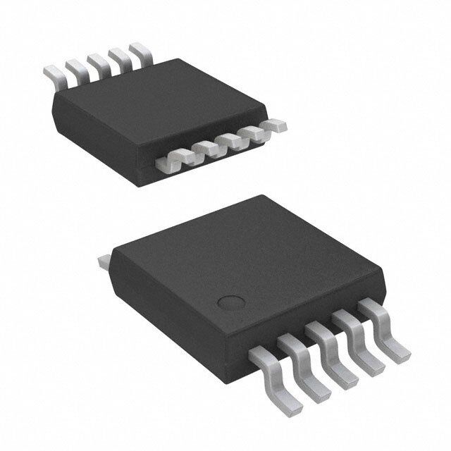
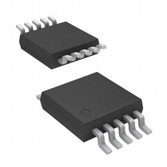
| 产品图片 |
|
| rohs | 符合RoHS无铅 / 符合限制有害物质指令(RoHS)规范要求 |
| 产品系列 | 电源管理 IC,稳压器—开关式稳压器,Texas Instruments TPS60310DGSR- |
| 数据手册 | |
| 产品型号 | TPS60310DGSR |
| PWM类型 | - |
| 产品目录页面 | |
| 产品种类 | 稳压器—开关式稳压器 |
| 供应商器件封装 | 10-VSSOP |
| 其它名称 | 296-13414-6 |
| 包装 | Digi-Reel® |
| 单位重量 | 18.800 mg |
| 同步整流器 | 无 |
| 商标 | Texas Instruments |
| 安装类型 | 表面贴装 |
| 安装风格 | SMD/SMT |
| 宽度 | 3 mm |
| 封装 | Reel |
| 封装/外壳 | 10-TFSOP,10-MSOP(0.118",3.00mm 宽) |
| 封装/箱体 | VSSOP-10 |
| 工作温度 | -40°C ~ 125°C |
| 工作温度范围 | - 40 C to + 125 C |
| 工厂包装数量 | 2500 |
| 开关频率 | 700 kHz |
| 拓扑结构 | Boost |
| 最大工作温度 | + 125 C |
| 最大输入电压 | 1.8 V |
| 最小工作温度 | - 40 C |
| 最小输入电压 | 0.9 V |
| 标准包装 | 1 |
| 电压-输入 | 0.9 V ~ 1.8 V |
| 电压-输出 | 3.3V,1.8 V ~ 3.6 V |
| 电流-输出 | 40mA,20mA |
| 类型 | 升压(升压),切换电容(充电泵) |
| 系列 | TPS60310 |
| 输入电压 | 0.9 V to 1.8 V |
| 输出数 | 2 |
| 输出电压 | 3.3 V |
| 输出电流 | 20 mA, 40 mA |
| 输出端数量 | 2 Output |
| 输出类型 | 固定和可调 |
| 频率-开关 | 700kHz |


- 商务部:美国ITC正式对集成电路等产品启动337调查
- 曝三星4nm工艺存在良率问题 高通将骁龙8 Gen1或转产台积电
- 太阳诱电将投资9.5亿元在常州建新厂生产MLCC 预计2023年完工
- 英特尔发布欧洲新工厂建设计划 深化IDM 2.0 战略
- 台积电先进制程称霸业界 有大客户加持明年业绩稳了
- 达到5530亿美元!SIA预计今年全球半导体销售额将创下新高
- 英特尔拟将自动驾驶子公司Mobileye上市 估值或超500亿美元
- 三星加码芯片和SET,合并消费电子和移动部门,撤换高东真等 CEO
- 三星电子宣布重大人事变动 还合并消费电子和移动部门
- 海关总署:前11个月进口集成电路产品价值2.52万亿元 增长14.8%


PDF Datasheet 数据手册内容提取
TPS60310, TPS60311, TPS60312, TPS60313 SINGLE-CELL TO 3-V/3.3-V, 20-mA DUAL OUTPUT, HIGH-EFFICIENCY CHARGE PUMP WITH SNOOZE MODE SLVS362A – MAY 2001 – REVISED AUGUST 2001 features applications (cid:1) (cid:1) Regulated 3-V or 3.3-V Output Voltage With Pagers up to 20-mA Output Current From a (cid:1) Battery-Powered Toys 0.9-V to 1.8-V Input Voltage Range (cid:1) Portable Measurement Instruments (cid:1) High Power Conversion Efficiency (up to (cid:1) Home Automation Products 90%) Over Wide Output Current Range, (cid:1) Medical Instruments (Like Hearing Optimized for 1.2-V Battery Voltage (cid:1) Instruments) Snooze Mode for Improved Efficiency at (cid:1) Metering Applications Using MSP430 Low-Output Current (cid:1) Microcontroller Additional Output With 2 Times V (OUT1) I (cid:1) (cid:1) Device Quiescent Current Less Than 2 µA Portable Smart Card Readers (cid:1) Supervisor Included; Open Drain or DGS PACKAGES Push-Pull Power Good Output (TOP VIEW) (cid:1) No Inductors Required/Low EMI SNOOZE 1 10 PG (cid:1) Only Five Small, 1-µF Ceramic Capacitors C1– 2 9 GND Required VIN 3 8 C2– (cid:1) Microsmall 10-Pin MSOP Package C1+ 4 7 C2+ OUT1 5 6 OUT2 description The TPS6031X step-up, regulated charge pumps generate a 3-V ±4% or 3.3-V ±4% output voltage ACTUAL SIZE from a 0.9-V to 1.8-V input voltage (one alkaline, 3,05 mm x 4,98 mm NiCd, or NiMH battery). Only five small 1-µF ceramic capacitors are required to build a complete high-efficiency dc/dc charge pump converter. To achieve the high efficiency over a wide input voltage range, the charge pump automatically selects between a 3x or 4x conversion mode. typical application circuit EFFICIENCY vs C1F C2F 1 µF 1 µF OUTPUT CURRENT (OUT2) 90 Snooze Mode 2 4 8 7 80 0.9 V toIN 1P.8U VT 3 C1– C1+ C2– OCU2T+1 5 2× IN 70 VIN + Max 40 mA % 60 1C µINF + TPS60310 OUT2 6 C1 (µO+FUT1) 3M.a3x V 2±04 m%A ciency – 4500 Normal Mode 1 R C1 (µOFUT2) Effi 30 SNOOZE 10 PG 20 ON/OFF GND 9 10 VI = 1.3 V 0 0.001 0.01 0.1 1 10 100 IO – Output Current (OUT2) – mA Snooze mode improves efficiency at an output current in the range of 1 µA to 100 µA. Please be aware that an important notice concerning availability, standard warranty, and use in critical applications of TexasInstruments semiconductor products and disclaimers thereto appears at the end of this data sheet. PRODUCTION DATA information is current as of publication date. Copyright 2001, Texas Instruments Incorporated Products conform to specifications per the terms of Texas Instruments standard warranty. Production processing does not necessarily include testing of all parameters. POST OFFICE BOX 655303 • DALLAS, TEXAS 75265 1
TPS60310, TPS60311, TPS60312, TPS60313 SINGLE-CELL TO 3-V/3.3-V, 20-mA DUAL OUTPUT, HIGH-EFFICIENCY CHARGE PUMP WITH SNOOZE MODE SLVS362A – MAY 2001 – REVISED AUGUST 2001 description (continued) Output 1 (OUT1) can deliver a maximum of 40 mA, from a 1-V input, with output 2 (OUT2) not loaded. OUT2 can deliver a maximum of 20 mA, from a 1-V input, with OUT1 not loaded. Both outputs can be loaded at the same time, but the total output current of the first voltage doubler must not exceed 40 mA. For example, the load at OUT1 is 20 mA and the load at output 2 is 10 mA. In snooze mode, the devices operate with a typical operating current of 2 µA, while the output voltage is maintained at 3.3 V ±10% or 3 V ±10%, respectively. This is lower than the self-discharge current of most batteries. Load current in snooze mode is limited to 2 mA. If the load current increases above 2 mA, the output voltage drops further and the devices automatically exits the snooze mode and operate in normal mode to regulate to the nominal output voltage with higher output currents. The device is set into the snooze mode by taking the SNOOZE pin low, and is set into normal operating mode by taking the SNOOZE pin high. A power-good function supervises the output voltage of OUT2 and can be used for power up and power down sequencing. Power-good (PG) is offered as either open-drain or push-pull output. AVAILABLE OPTIONS OUTPUT OUTPUT OUTPUT OUTPUT PART MARKING DGS NUMBER† PACKAGE CURRENT 1 CURRENT 2 VOLTAGE 1 VOLTAGE 2 FEATURE [mA]‡ [mA]§ [V] [V] TPS60310DGS ATG 40 20 2 x VIN 3.3 Open-drain power-good output TPS60311DGS ATI 40 20 2 x VIN 3 Open-drain power-good output TPS60312DGS ATK 40 20 2 x VIN 3.3 Push-pull power-good output TPS60313DGS ATL 40 20 2 x VIN 3 Push-pull power-good output †The DGS package is available taped and reeled. Add R suffix to device type (e.g. TPS60310DGSR) to order quantities of 2500 devices per reel. ‡If OUT2 is not loaded. §If OUT1 is not loaded. 2 POST OFFICE BOX 655303 • DALLAS, TEXAS 75265
TPS60310, TPS60311, TPS60312, TPS60313 SINGLE-CELL TO 3-V/3.3-V, 20-mA DUAL OUTPUT, HIGH-EFFICIENCY CHARGE PUMP WITH SNOOZE MODE SLVS362A – MAY 2001 – REVISED AUGUST 2001 TPS60310 and TPS60311 functional block diagram C1F C1– C1+ CP1 OUT1 2x (Doubler) VIN Charge Pump PG _ (Push-Pull Output SNOOZE Control Oscillator for TPS60312 and + TPS60313) _ Reg + Vref + _ CP2 1.5x/2x Charge Pump OUT2 C2– C2+ GND C2F Terminal Functions TERMINAL II//OO DDEESSCCRRIIPPTTIIOONN NAME NO. C1+ 4 Positive terminal of the flying capacitor C1F C1– 2 Negative terminal of the flying capacitor C1F C2+ 7 Positive terminal of the flying capacitor C2F C2– 8 Negative terminal of the flying capacitor C2F GND 9 GROUND OUT1 5 O 2 × VIN power output. Bypass OUT1 to GND with the output filter capacitor C(OUT1). OUT2 6 O Regulated 3.3-V power output (TPS60310, TPS60312) or 3-V power output (TPS60311, TPS60313), respectively Bypass OUT2 to GND with the output filter capacitor C(OUT2). PG 10 O Power good detector output. As soon as the voltage on OUT2 reaches about 98% of its nominal value this pin goes high. Open drain output on TPS60310 and TPS60311. A pullup resistor should be connected between PG and OUT1 or OUT2. Push-pull output stage on TPS60312 and TPS60313 SNOOZE 1 I Snooze mode enable input – SNOOZE = Low enables the snooze mode at low output current. – SNOOZE = High disables the snooze mode. VIN 3 I Supply input. Bypass VIN to GND with a ≥ 1-µF capacitor. POST OFFICE BOX 655303 • DALLAS, TEXAS 75265 3
TPS60310, TPS60311, TPS60312, TPS60313 SINGLE-CELL TO 3-V/3.3-V, 20-mA DUAL OUTPUT, HIGH-EFFICIENCY CHARGE PUMP WITH SNOOZE MODE SLVS362A – MAY 2001 – REVISED AUGUST 2001 detailed description operating principle The TPS6031X charge pumps are voltage quadruplers that provide a regulated 3.3-V or 3-V output from a 0.9-V to 1.8-V input. They deliver a maximum load current of 20 mA. Designed specifically for space critical battery powered applications, the complete converter requires only five external capacitors and enables the design to use low-cost, small-sized, 1-µF ceramic capacitors. The TPS6031X circuits consist of an oscillator, a voltage reference, an internal resistive feedback circuit, two error amplifiers, two charge pump stages with MOSFET switches, a shutdown/start-up circuit, and a control circuit. snooze mode The devices contain a circuit which dramatically reduces the quiescent current at light loads. This so called snooze mode must be enabled by pulling the SNOOZE pin low. When the output current decreases below the snooze mode threshold, the device enters the snooze mode. In snooze mode, the main error amplifier with 4% error and 50-µA supply current is disabled and a 10%, 2-µA regulator controls the output voltage. start-up procedure The start-up performance of the device is independent of the level of the snooze input. When voltage is applied to the input, CP1 will first enter a dc start-up mode during which the capacitor on OUT1 is charged up to about V . After that, it starts switching to boost the voltage further up to about two times V . CP1 first enters a dc IN IN start-up mode during which the capacitor on OUT1 is charged up to about V . CP2 then follows and charges IN up the capacitor on OUT2 to about the voltage on OUT1, after that, it also starts switching and boosts up the voltage to its nominal value. The voltage at the SNOOZE pin must not exceed the highest voltage applied to the device. NOTE: During start-up with V = 0 V, the highest voltage is the input voltage. OUT power-good detector The power-good output is an open-drain output on the TPS60310 and TPS60311 or a push-pull output on the TPS60312 and TPS60313. The PG-output pulls low when the output of OUT2 is out of regulation. When the output rises to within 98% of regulation, the power-good output goes active high. In shutdown, power-good is pulled low. In normal operation, an external pullup resistor with the TPS60310 and TPS60311 is typically used to connect the PG pin to VOUT. The resistor should be in the 100-kΩ to 1-MΩ range. If the PG output is not used, it should remain unconnected. Output current at PG (TPS60312, TPS60313) reduces maximum output current at OUT2. In snooze mode, the output voltage is sampled at a rate up to 2 ms and is applied to the power-good comparator. In normal mode, the output voltage is measured continuously. 4 POST OFFICE BOX 655303 • DALLAS, TEXAS 75265
TPS60310, TPS60311, TPS60312, TPS60313 SINGLE-CELL TO 3-V/3.3-V, 20-mA DUAL OUTPUT, HIGH-EFFICIENCY CHARGE PUMP WITH SNOOZE MODE SLVS362A – MAY 2001 – REVISED AUGUST 2001 absolute maximum ratings over operating free-air temperature (unless otherwise noted)† Input voltage, V (IN to GND) (see Note 1) . . . . . . . . . . . . . . . . . . . . . . . . . . . . . . . . . . . . . . . . . . . . . –0.3 V to 2 V I Output voltage, V (OUT1, OUT2, EN, PG to GND) (see Note 1) . . . . . . . . . . . . . . . . . . . . . . . . –0.3 V to 3.6 V O Voltage, (C1+ to GND) . . . . . . . . . . . . . . . . . . . . . . . . . . . . . . . . . . . . . . . . . . . . . . . . . . –0.3 V to V + 0.3 V O(OUT1) Voltage, (C1– to GND, C2– to GND) . . . . . . . . . . . . . . . . . . . . . . . . . . . . . . . . . . . . . . . . . . . –0.3 V to V + 0.3 V IN Voltage, (C2+ to GND) . . . . . . . . . . . . . . . . . . . . . . . . . . . . . . . . . . . . . . . . . . . . . . . . . . –0.3 V to V + 0.3 V O(OUT2) Continuous power dissipation . . . . . . . . . . . . . . . . . . . . . . . . . . . . . . . . . . . . . . . . . . See Dissipation Rating Table Output current, I (OUT1) . . . . . . . . . . . . . . . . . . . . . . . . . . . . . . . . . . . . . . . . . . . . . . . . . . . . . . . . . . . . . . . . . 80 mA O Output current, I (OUT2) . . . . . . . . . . . . . . . . . . . . . . . . . . . . . . . . . . . . . . . . . . . . . . . . . . . . . . . . . . . . . . . . . 40 mA O Storage temperature range, T . . . . . . . . . . . . . . . . . . . . . . . . . . . . . . . . . . . . . . . . . . . . . . . . . . . . –55°C to 150°C stg Maximum junction temperature, T . . . . . . . . . . . . . . . . . . . . . . . . . . . . . . . . . . . . . . . . . . . . . . . . . . . . . . . . . 150°C J †Stresses beyond those listed under “absolute maximum ratings” may cause permanent damage to the device. These are stress ratings only, and functional operation of the device at these or any other conditions beyond those indicated under “recommended operating conditions” is not implied. Exposure to absolute-maximum-rated conditions for extended periods may affect device reliability. NOTE 1: The voltage at SNOOZE and PG can exceed IN up to the maximum rated voltage without increasing the leakage current drawn by these pins. DISSIPATION RATING TABLE TA <25(cid:2)C DERATING FACTOR TA = 70(cid:2)C TA = 85(cid:2)C PACKAGE POWER RATING ABOVE TA = 25(cid:2)C POWER RATING POWER RATING DGS 424 mW 3.4 mW/(cid:2)C 271 mW 220 mW NOTE: The thermal resistance junction to ambient of the DGS package is RTH–JA = 294(cid:2)C/W. recommended operating conditions MIN NOM MAX UNIT Input voltage, VI 0.9 1.8 V Output current (OUT2), IO(OUT2) 20 mA Output current (OUT1), IO(OUT1) 40 mA Input capacitor, CI 1 µF Flying capacitors, C1F, C2F 1 µF Output capacitors, CO(1), CO(2) 1 µF Operating junction temperature, TJ –40 125 °C POST OFFICE BOX 655303 • DALLAS, TEXAS 75265 5
TPS60310, TPS60311, TPS60312, TPS60313 SINGLE-CELL TO 3-V/3.3-V, 20-mA DUAL OUTPUT, HIGH-EFFICIENCY CHARGE PUMP WITH SNOOZE MODE SLVS362A – MAY 2001 – REVISED AUGUST 2001 electrical characteristics at C = C1F = C2F = C = C = 1 µF, T = –40°C to 85°C, IN (OUT1) (OUT2) C V = 1 V, V = V (unless otherwise noted) IN (SNOOZE) IN PARAMETER TEST CONDITIONS MIN TYP MAX UNIT VIN Supply voltage range 0.9 1.8 V VIN ≥ 1.1 V, IO(OUT2) = 0 mA, 40 I(PG,1) = 0 mA IIO(OUT1) VIN = 0.9 V, IO(OUT2) = 0 mA, 20 MMaaxxiimmuumm oouuttpuutt ccuurrrreenntt ffoorr TTPPSS6600331100,, I(PG,1) = 0 mA mmAA TPS60312 VIN ≥ 1.1 V, IO(OUT1) = 0 mA, 20 I(PG,1) = 0 mA IIOO((OOUUTT22)) VIN = 0.9 V, IO(OUT1) = 0 mA, 10 I(PG,1) = 0 mA VIN ≥ 1.1 V, IO(OUT2) = 0 mA, 40 I(PG,1) = 0 mA IIO(OUT1) VIN = 0.9 V, IO(OUT2) = 0 mA, Maximum output current for TPS60311, I(PG,1) = 0 mA 20 TTPPSS6600331133 mmAA VIN ≥ 1 V, IO(OUT1) = 0 mA, 20 I(PG,1) = 0 mA IIO(OUT2) VIN = 0.9 V, IO(OUT1) = 0 mA, 12 I(PG,1) = 0 mA 1.1 V < VIN < 1.8 V, IO(OUT1) = 0 mA 3.17 3.3 3.43 0 < IO(OUT2) < 20 mA VV 0.9 V < VIN < 1.1 V, VO(OUT2) Output voltage for TPS60310, TPS60312 IO(OUT1) = 0 mA, IO(OUT2) < 10 mA 3.17 3.3 3.43 0.9 V < VIN < 1.8 V, V(SNOOZE) = 0 V, 0 < IO(OUT2) < 1 mA or 2.85 3.3 3.6 V 0 < IO(OUT1) < 2 mA 1 V < VIN < 1.8 V, IO(OUT1) = 0 mA, 2.88 3 3.12 0 < IO(OUT2) < 20 mA VV VIN > 1.65 V, IO(OUT1) = 0 mA, VO(OUT2) Output voltage for TPS60311, TPS60313 25 µA < IO(OUT2) < 20 mA 2.88 3 3.15 0.9 V < VIN < 1.8 V, V(SNOOZE) = 0 V, 0 < IO(OUT2) < 1 mA or 2.6 3.3 3.27 V 0 < IO(OUT1) < 2 mA OUT2 IO(OUT2) = 20 mA, IO(OUT1) = 0 mA 30 VVP–P OOuuttppuutt vvoollttaaggee rriippppllee mmVVP–P OUT1 IO(OUT1) = 40 mA, IO(OUT2) = 0 mA 60 IQ Quiescent current (no-load input current) IO = 0 mA, VIN = 1.8 V 35 70 µA VIN = 1.65 V, V(SNOOZE) = 0 V, 2 10 TC = 60°C II(SQ) QQuuiieesscceenntt ssuuppppllyy ccuurrrreenntt iinn ssnnoooozzee mmooddee µAA VIN = 1.65 V, V(SNOOZE) = 0 V, 1.5 4 TC ≤ 25°C fOSC Internal switching frequency 470 700 900 kHz VIL(EN) EN input low voltage VIN = 0.9 V to 1.8 V 0.3×VIN V VIH(EN) EN input high voltage VIN = 0.9 V to 1.8 V 0.7×VIN V Ilkg EN input leakage current VVO(E(NO)U =T 01 )V or VIN or VO(OUT2) or 0.01 0.1 µA LinSkip switching threshold VIN = 1.25 V 7.5 mA IO(OUT1) 2 8 mA SSnnoooozzee mmooddee tthhrreesshhoolldd VVIINN == 11.2255 VV IO(OUT2) 1 4 mA 6 POST OFFICE BOX 655303 • DALLAS, TEXAS 75265
TPS60310, TPS60311, TPS60312, TPS60313 SINGLE-CELL TO 3-V/3.3-V, 20-mA DUAL OUTPUT, HIGH-EFFICIENCY CHARGE PUMP WITH SNOOZE MODE SLVS362A – MAY 2001 – REVISED AUGUST 2001 electrical characteristics at C = C1F = C2F = C = C = 1 µF, T = –40°C to 85°C, IN (OUT1) (OUT2) C V = 1 V, V = V (unless otherwise noted) (continued) IN (SNOOZE) IN PARAMETER TEST CONDITIONS MIN TYP MAX UNIT VO(OUT2) = 0 V 5 20 50 SShhoorrtt cciirrccuuiitt ccuurrrreenntt VVIN = 11.88 VV mmAA VO(OUT1) = 0 V 2 80 150 VIN = 1.25 V, TC = 25°C Output load regulation 0.1 %/mA 2 mA < IO(OUT2) < 20 mA 1 V < VIN < 1.65 V, TC = 25°C, 0.75 %/V IO(OUT) = 10 mA OOuuttppuutt lliinnee rreegguullaattiioonn 1 V < VIN < 1.65 V, TC = 25°C, 1 %/V IO(OUT2) = 1 mA, V(SNOOZE) = 0 V No load start-up time 400 µs Impedance of first charge pump stage 4.0 Ω VIN ≥1.1 V 165 SSttartt-up perfformance att OOUUTT22 ((miiniimum sttartt-up lloadd VIN ≥1 V 330 ΩΩ rreessiissttaannccee)) VIN = 0.9 V 1000 Startup performance at OUT1 (minimum start-up load resistance) VIN = 1 V 500 Ω electrical characteristics for power good comparator of devices TPS6031X at T = –40°C to 85°C, C V = 1 V and V = V (unless otherwise noted) IN (SNOOZE) IN PARAMETER TEST CONDITIONS MIN TYP MAX UNIT V(PG) Power-good trip voltage VO ramping positive VO – 1% VO V Vhys Power-good trip voltage hysteresis VO ramping negative 10% VOL Power-good output voltage low VO = 0 V, I(PG) = 1.6 mA 0.3 V TPS60310 VO = 3.3 V, V(PG) = 3.3 V 0.01 0.1 IIlkg PPoowweerr-ggoooodd lleeaakkaaggee ccuurrrreenntt µAA TPS60311 VO = 3 V, V(PG) = 3 V 0.01 0.1 TPS60312 3 VVOH PPoowweerr-ggoooodd oouuttppuutt vvoollttaaggee hhiigghh IIO(PG) = –55 mmAA VV TPS60313 2.7 TPS60312, IO(PG,1) Output current at power good (source) TPS60313 –5 mA IO(PG,0) Output current at power good (sink) All devices V(PG) = 0 V 1.6 mA TPS60312, R(PG,1) OOuuttpuutt rreessiissttaannccee aatt poowweerr ggoooodd TPS60313 V(PG) = VO(OUT2) 15 Ω R(PG,0) All devices V(PG) = 0 V 100 Ω POST OFFICE BOX 655303 • DALLAS, TEXAS 75265 7
TPS60310, TPS60311, TPS60312, TPS60313 SINGLE-CELL TO 3-V/3.3-V, 20-mA DUAL OUTPUT, HIGH-EFFICIENCY CHARGE PUMP WITH SNOOZE MODE SLVS362A – MAY 2001 – REVISED AUGUST 2001 TYPICAL CHARACTERISTICS Table of Graphs FIGURE η Efficiency vs Output current (TPS60310 and TPS60311) 1, 2 IS Supply current vs Output current 3 IQ Quiescent current vs Input voltage 4 VO(OUT2) Output voltage at OUT2 vs Output current (TPS60310 and TPS60311) 5, 6 VO(OUT1) Output voltage at OUT1 vs Output current at 25°C, VI = 0.9 V, 1.1 V, 1.25 V, 1.4 V, 1.6 V, 1.8 V 7 VO(OUT2) Output voltage at OUT2 vs Input voltage (TPS60310 and TPS60311) 8, 9 VO(OUT1) Output voltage at OUT1 vs Input voltage (TPS60310 and TPS60311) 10 VO(OUT2) Output voltage at OUT2 vs Free-air temperature (TPS60310, TPS60312, TPS60311, and TPS60313) 11, 12 VO(OUT2) Output voltage ripple at OUT2 13 Minimum input voltage vs Output current for TPS60310, TPS60312, TPS60311, and TPS60313 14, 15 Start-up timing enable 16 Switching frequency vs Input voltage 17 Load transient response 18 Line transient response 19 VO Output voltage vs Time 20 Output voltage ripple in Snooze mode 21 TYPICAL CHARACTERISTICS TPS60310, TPS60312 TPS60311, TPS60313 EFFICIENCY EFFICIENCY vs vs OUTPUT CURRENT OUTPUT CURRENT 90 90 80 VI = 0.9 V 80 VI = 0.9 V 70 70 VI = 1.25 V VI = 1.25 V 60 60 % % – – y 50 VI = 1.8 V y 50 VI = 1.8 V c c n n e e ci 40 ci 40 Effi Effi 30 30 20 20 V(Snooze) = VI V(Snooze) = VI 10 10 0 0 0.1 1 10 100 0.1 1 10 100 IO – Output Current – mA IO – Output Current – mA Figure 1 Figure 2 8 POST OFFICE BOX 655303 • DALLAS, TEXAS 75265
TPS60310, TPS60311, TPS60312, TPS60313 SINGLE-CELL TO 3-V/3.3-V, 20-mA DUAL OUTPUT, HIGH-EFFICIENCY CHARGE PUMP WITH SNOOZE MODE SLVS362A – MAY 2001 – REVISED AUGUST 2001 TYPICAL CHARACTERISTICS TPS60310 TPS6031X SUPPLY CURRENT QUIESCENT CURRENT vs vs OUTPUT CURRENT INPUT VOLTAGE 140 36 120 34 TA = –40°C A VI = 0.9 V A 32 y Current – m 18000 VI = 1.8 V µnt Current – 2380 TA = T2A5° =C 85°C uppl 60 VI = 1.25 V esce 26 – S Qui C 40 C 24 I V(Snooze) = VI 20 22 0 20 0 10 20 30 40 0.80 1 1.20 1.40 1.60 1.80 2 IO – Output Current – mA VI – Input Voltage – V Figure 3 Figure 4 TPS60310, TPS60312 TPS60311, TPS60313 OUTPUT VOLTAGE (OUT2) OUTPUT VOLTAGE (OUT2) vs vs OUTPUT CURRENT (OUT2) OUTPUT CURRENT (OUT2) 3.4 3.2 VI = 1.8 V 3.1 VI = 1.25 V VI = 1.8 V 3.2 V VI = 1.25 V V – – 3 e e g g a a Volt 3 VI = 1.1 V Volt 2.9 VI = 1.1 V utput VI = 0.9 V utput VI = 0.9 V O O 2.8 – – VO 2.8 VO 2.7 2.6 2.6 0 10 20 30 40 0 10 20 30 40 IO – Output Current (OUT2) – mA IO – Output Current (OUT2) – mA Figure 5 Figure 6 POST OFFICE BOX 655303 • DALLAS, TEXAS 75265 9
TPS60310, TPS60311, TPS60312, TPS60313 SINGLE-CELL TO 3-V/3.3-V, 20-mA DUAL OUTPUT, HIGH-EFFICIENCY CHARGE PUMP WITH SNOOZE MODE SLVS362A – MAY 2001 – REVISED AUGUST 2001 TYPICAL CHARACTERISTICS TPS60310, TPS60312 TPS60310, TPS60312 OUTPUT VOLTAGE (OUT1) OUTPUT VOLTAGE (OUT2) vs vs OUTPUT CURRENT (OUT1) INPUT VOLTAGE 4 3.35 3.3 3.5 VI = 1.8 V V – 2) 3.25 IO(OUT2) = 0.1 mA V T age – 3 VI = 1.6 V e (OU 3.2 IO(OUT2) = 1 mA IO(OUT2) = 10 mA olt ag ut V VI = 1.4 V Volt IO(OUT2) = 20 mA utp 2.5 VI = 1.25 V put 3.15 – O Out O VI = 1.1 V – 3.1 V O 2 V VI = 0.9 V 3.05 1.5 3 0 20 40 60 0.8 1 1.2 1.4 1.6 1.8 IO – Output Current (OUT1) – mA VI – Input Voltage – V Figure 7 Figure 8 TPS60310, TPS60312 TPS6031x OUTPUT VOLTAGE (OUT2) OUTPUT VOLTAGE (OUT1) vs vs INPUT VOLTAGE INPUT VOLTAGE 3.1 3.5 IO(OUT2) = 0.1 mA IO(OUT2) = 1 mA IO(OUT1) = 0.1 mA V 3.05 V 2) – 1) – 3 T T U U O O IO(OUT1) = 10 mA e ( 3 IO(OUT2) = 10 mA e ( g g a a olt IO(OUT2) = 20 mA olt 2.5 V V ut 2.95 ut IO(OUT1) = 40 mA p p ut ut O O – – 2 VO 2.9 VO 2.85 1.5 0.8 1 1.2 1.4 1.6 1.8 0.8 1 1.2 1.4 1.6 1.8 VI – Input Voltage – V VI – Input Voltage – V Figure 9 Figure 10 10 POST OFFICE BOX 655303 • DALLAS, TEXAS 75265
TPS60310, TPS60311, TPS60312, TPS60313 SINGLE-CELL TO 3-V/3.3-V, 20-mA DUAL OUTPUT, HIGH-EFFICIENCY CHARGE PUMP WITH SNOOZE MODE SLVS362A – MAY 2001 – REVISED AUGUST 2001 TYPICAL CHARACTERISTICS TPS60310, TPS60312 TPS60311, TPS60313 OUTPUT VOLTAGE (OUT2) OUTPUT VOLTAGE (OUT2) vs vs FREE-AIR TEMPERATURE FREE-AIR TEMPERATURE 3.40 3.04 VI = 1 V VI = 1.8 V 3.02 VI = 1.25 V V 3.30 ge (OUT2) – 3.20 VI = 1.25 V VI = 1.8 V e (OUT2) – V 2.938 VI = 1 V a g Volt 3.10 olta put ut V 2.96 – OutO 3 – Outp 2.94 V O V 2.90 2.92 2.80 2.90 –40 10 60 110 –40 10 60 110 TA – Free-Air Temperature – °C TA – Free-Air Temperature – °C Figure 11 Figure 12 TPS60310, TPS60312 MINIMUM INPUT VOLTAGE TPS6031x vs OUTPUT VOLTAGE RIPPLE (OUT2) OUTPUT CURRENT 1.20 IO(OUT2) = 20 mA, 1.15 VI = 1.2 V V – 1.10 ge TA = 85°C a 1.05 olt 10 mV/DIV ut V 1.00 TA = –40°C p n m I 0.95 u m 0.90 ni Mi – n) 0.85 VI(mi 0.80 TA = 25°C 0.75 500 ns/DIV 0.70 0.10 1 10 100 IO – Output Current – mA Figure 13 Figure 14 POST OFFICE BOX 655303 • DALLAS, TEXAS 75265 11
TPS60310, TPS60311, TPS60312, TPS60313 SINGLE-CELL TO 3-V/3.3-V, 20-mA DUAL OUTPUT, HIGH-EFFICIENCY CHARGE PUMP WITH SNOOZE MODE SLVS362A – MAY 2001 – REVISED AUGUST 2001 TYPICAL CHARACTERISTICS TPS60311, TPS60313 MINIMUM INPUT VOLTAGE vs OUTPUT CURRENT START-UP TIMING ENABLE 1.20 1.15 VO(OUT2) V 2 V/DIV – 1.10 e g olta 1.05 VO(OUT1) V ut 1.00 p 2 V/DIV n m I 0.95 u m 0.90 IIN ni Mi – n) 0.85 TA = 85°C 100 mA/DIV V(EN) VI(mi 0.80 TA = 25°C TA = –40°C 1 V/DIV 0.75 50 us/DIV 0.70 0.10 1 10 100 IO – Output Current – mA Figure 15 Figure 16 SWITCHING FREQUENCY vs INPUT VOLTAGE LOAD TRANSIENT RESPONSE 730 20 mV/DIV 720 TA = 85°C z 710 kH VO(OUT2) – cy 700 en TA = 25°C VI = 1.25 V, u Load Step 2 mA to eq 690 18 mA to 2 mA, g Fr TA = –40°C TA = 25°C hin 680 c wit S 670 10 mA/DIV 660 IO(OUT2) 20 us/DIV 650 0.8 1.3 1.8 VI – Input Voltage – V Figure 18 Figure 17 12 POST OFFICE BOX 655303 • DALLAS, TEXAS 75265
TPS60310, TPS60311, TPS60312, TPS60313 SINGLE-CELL TO 3-V/3.3-V, 20-mA DUAL OUTPUT, HIGH-EFFICIENCY CHARGE PUMP WITH SNOOZE MODE SLVS362A – MAY 2001 – REVISED AUGUST 2001 TYPICAL CHARACTERISTICS LINE TRANSIENT RESPONSE VI = 1.1 V to 1.7 V to 1.1 V, IO(OUT2) = 20 mA TA = 25°C VO(OUT2) 50 mV/DIV VI 1 V/DIV 500 us/DIV Figure 19 OUTPUT VOLTAGE vs TIME OUTPUT VOLTAGE RIPPLE IN SNOOZE MODE VI = 1.25 V, VI = 1.25 V, IO(OUT2) = 1 mA, IO(OUT2) = 1 mA, CO(OUT2) = 1 µF CO(OUT2) = 10 µF VO(OUT2) 100 mV/DIV VO(OUT2) 100 mV/DIV 1 V/DIV V(Snooze) 200 us/DIV 200 us/DIV Figure 20 Figure 21 POST OFFICE BOX 655303 • DALLAS, TEXAS 75265 13
TPS60310, TPS60311, TPS60312, TPS60313 SINGLE-CELL TO 3-V/3.3-V, 20-mA DUAL OUTPUT, HIGH-EFFICIENCY CHARGE PUMP WITH SNOOZE MODE SLVS362A – MAY 2001 – REVISED AUGUST 2001 APPLICATION INFORMATION design procedure capacitor selection The TPS6031X devices require only five external capacitors. Their values are closely linked to the required output current and the output noise and ripple requirements. It is possible to only use 1-µF capacitors of the same type. The input capacitor improves system efficiency by reducing the input impedance and stabilizing the input current. The minimum required capacitance of the output capacitor (C ) that can be selected is 1 µF. Depending on the O maximum allowed output ripple voltage, larger values can be chosen. Table 1 shows capacitor values recommended for low output voltage ripple operation. A recommendation is given for the smallest size. Table 1. Recommended Capacitor Values for Low-Output Voltage Ripple Operation CIN CXF COUT VP–P VIN IO(OUT2) [µF] [µF] [µF] [mV] [[VV]] [[mmAA]] AATT 2200 mmAA// CERAMIC CERAMIC CERAMIC VIN = 1.1 V 0.9...1.8 0…20 1 1 1 16 0.9…1.8 0…20 1 1 2.2 10 0.9…1.8 0…20 1 1 10 // 0.1 6 Table 2. Recommended Capacitors MANUFACTURER PART NUMBER SIZE CAPACITANCE TYPE Taiyo Yuden UMK212BJ104MG 0805 0.1 µF Ceramic LMK212BJ105KG 0805 1 µF Ceramic LMK212BJ225MG 0805 2.2 µF Ceramic JMK316BJ475KL 1206 4.7 µF Ceramic AVX 0805ZC105KAT2A 0805 1 µF Ceramic 1206ZC225KAT2A 1206 2.2 µF Ceramic Table 3 lists the manufacturers of recommended capacitors. However, ceramic capacitors will provide the lowest output voltage ripple due to their typically lower ESR. Table 3. Recommended Capacitor Manufacturers MANUFACTURER CAPACITOR TYPE INTERNET Taiyo Yuden X7R/X5R ceramic www.t-yuden.com AVX X7R/X5R ceramic www.avxcorp.com Vishay X7R/X5R ceramic www.vishay.com Kemet X7R/X5R ceramic www.kemet.com TDK X7R/X5R ceramic www.component.tdk.com 14 POST OFFICE BOX 655303 • DALLAS, TEXAS 75265
TPS60310, TPS60311, TPS60312, TPS60313 SINGLE-CELL TO 3-V/3.3-V, 20-mA DUAL OUTPUT, HIGH-EFFICIENCY CHARGE PUMP WITH SNOOZE MODE SLVS362A – MAY 2001 – REVISED AUGUST 2001 APPLICATION INFORMATION capacitor selection (continued) INPUT 3 6 OUTPUT OUT2 0.9 V to 1.8 V + VIN + 3.3 V,20 mA CIN R1 C(OUT2) 1 µF 1 µF TPS60310 10 PG PG 4 7 C1+ C2+ C1F C2F 1 µF 2 8 1 µF C1– C2– 1 5 SNOOZE OUT1 + GND C(OUT1) 9 1 µF Figure 22. Typical Operating Circuit For the maximum output current and best performance, five ceramic capacitors of 1 µF are recommended. For lower currents or higher allowed output voltage ripple, other capacitors can be used. It is recommended that the input and output capacitors have a minimum value of 1 µF. This value is necessary to assure a stable operation of the system due to the linear mode. With flying capacitors lower than 1 µF, the maximum output power decreases. This means that the device works in the linear mode with lower output currents. output filter design The power-good output is capable of driving light loads up to 5 mA (see Figure 23). Therefore, the output resistance of the power-good pin with the output capacitor, can be used as an RC-filter. C1F C1– C1+ VIN Charge Pumps, OUT2 Logic C(OUT2) and Control R(PG1) _ SNOOZE PG + R(PG0) CPG + _ Vref OUT1 C(OUT1) C2– C2+ GND C2F Figure 23. TPS60312, TPS60313 Push-Pull Power-Good Output-Stage as Filtered Supply POST OFFICE BOX 655303 • DALLAS, TEXAS 75265 15
TPS60310, TPS60311, TPS60312, TPS60313 SINGLE-CELL TO 3-V/3.3-V, 20-mA DUAL OUTPUT, HIGH-EFFICIENCY CHARGE PUMP WITH SNOOZE MODE SLVS362A – MAY 2001 – REVISED AUGUST 2001 APPLICATION INFORMATION output filter design (continued) Due to R an output filter can easily be formed with an output capacitor (C ). Cutoff frequency is given (PG,1), PG by: ƒ (cid:1) 1 c 2(cid:1)R C (1) (PG,1) PG (cid:2) (cid:2) V and ratio V /V for the ac ripple is: (PG,1) (cid:1)(cid:6) 1 O I V (2) O(OUT2) (cid:4) (cid:5)2 1(cid:3) 2(cid:1)ƒR C (PG,1) PG with R = 15 Ω, C = 0.1 µF, and f = 600 kHz (at nominal switching frequency) (PG,1) P(cid:2)G (cid:2) V (PG,1) (cid:1)0.175 (3) V O(OUT2) Load current sourced by power-good output reduces maximum output current at OUT2. During start-up (power-good going high) current charging C discharges C . Therefore, C must not be larger than C PG (OUT2) PG PG ≤ 0.1 C(OUT2) or the device does not start. By charging CPG through C(OUT2), the output voltage at OUT2 decreases. If the capacitance of CPG is to large, the circuit detects power bad. The power-good output goes low and discharges C . Then the cycle starts again. Figure 24 shows a configuration with an LC-post filter to further PG reduce output ripple and noise. LP INPUT 3 6 OUT2 0.9 V to 1.8 V + VIN + CIN R1 C(OUT2) CP VP(OUT) 1 µF 1 µF TPS60310 10 PG PG 4 7 C1+ C2+ C1F C2F 1 µF 2 8 1 µF C1– C2– 1 5 SNOOZE OUT1 + ON/OFF GND C(OUT1) 9 1 µF Figure 24. LC-Post Filter Table 4. Recommended Values for Lowest Output Voltage Ripple VVIINN IIOO((OOUUTT22)) CCIINN[[µµFF]] CCXXFF[[µµFF]] CCOOUUTT[[µµFF]] CCPP[[µµFF]] VVPP((OOUUTT)) LLP[[µHH]] [V] [mA] CERAMIC CERAMIC CERAMIC CERAMIC VP–P[mV] 0.9…1.8 20 1 1 1 0.1 0.1 (X7R) 16 0.9…1.8 20 1 1 1 0.1 1 // 0.1 (X7R) 12 0.9…1.8 20 1 1 1 1 0.1 (X7R) 14 0.9…1.8 20 1 1 1 1 1 // 0.1 (X7R) 3 16 POST OFFICE BOX 655303 • DALLAS, TEXAS 75265
TPS60310, TPS60311, TPS60312, TPS60313 SINGLE-CELL TO 3-V/3.3-V, 20-mA DUAL OUTPUT, HIGH-EFFICIENCY CHARGE PUMP WITH SNOOZE MODE SLVS362A – MAY 2001 – REVISED AUGUST 2001 APPLICATION INFORMATION output filter design (continued) 6 3 OUT2 + R1 Display + VIN C(OUT2) 1 M MSP430 CIN 1 µF 1 µF TPS60312 10 PG 1.5 V 4 C1+ C2+ 7 CPG C1F C2F 0.1 µF 1 µF 2 8 1 µF Amplifier Sensor C1– C2– 1 5 ON SNOOZE OUT1 + GND C(OUT1) 9 1 µF Figure 25. Application With MSP430; PG as Supply for Analog Circuits power dissipation As given in the data sheet, the thermal resistance of the unsoldered package is RθJA = 294°C/W. Soldered on the EVM, a typical thermal resistance of RθJA(EVM) = 200°C/W was measured. The thermal resistance can be calculated using equation 4. T –T R (cid:1) J A (4) θJA P D Where: T is the junction temperature. J T is the ambient temperature. A P is the power that needs to be dissipated by the device. D The maximum power dissipation can be calculated using equation 5. P = V × I – V × I = V × (3 × I + I ) – V × I (5) D IN IN O O IN(max) O (SUPPLY) O O The maximum power dissipation happens with maximum input voltage and maximum output current: At maximum load the supply current is approximately 2 mA. P = 1.8 V × (3 × 20 mA + 2 mA) – 3.3 V × 20 mA = 46 mW (6) D With this maximum rating and the thermal resistance of the device on the EVM, the maximum temperature rise above ambient temperature can be calculated using equation 7. ∆TJ = RθJA × PD = 200°C/W × 46 mW = 10°C (7) This means that internal dissipation increases T by 10°C. J The junction temperature of the device must not exceed 125°C. This means the IC can easily be used at ambient temperatures up to: T = T – ∆T = 125°C – 10°C = 115°C (8) A J(max) J layout and board space All capacitors should be soldered as close as possible to the IC. A PCB layout proposal for a two-layer board is shown in Figure 26. Care has been taken to connect all capacitors as close as possible to the circuit to achieve optimized output voltage ripple performance. The bottom layer is not shown in Figure 26. It only consists of a ground-plane with a single track between the two vias that can be seen in the left part of the top layer. POST OFFICE BOX 655303 • DALLAS, TEXAS 75265 17
TPS60310, TPS60311, TPS60312, TPS60313 SINGLE-CELL TO 3-V/3.3-V, 20-mA DUAL OUTPUT, HIGH-EFFICIENCY CHARGE PUMP WITH SNOOZE MODE SLVS362A – MAY 2001 – REVISED AUGUST 2001 APPLICATION INFORMATION layout and board space (continued) PG 9,8 mm GND OUT2 GND VIN OUT1 0 mm EN 0 mm 7,62 mm Figure 26. Recommended PCB Layout for TPS6031X (top layer) device family products Other charge pump dc-dc converters in this family are: Table 5. Product Identification PART DESCRIPTION NUMBER TPS60100 2-cell to regulated 3.3-V, 200-mA low-noise charge pump TPS60101 2-cell to regulated 3.3-V, 100-mA low-noise charge pump TPS60110 3-cell to regulated 5-V, 300-mA low-noise charge pump TPS60111 3-cell to regulated 5-V, 150-mA low-noise charge pump TPS60120 2-cell to regulated 3.3-V, 200-mA high-efficiency charge pump with low-battery comparator TPS60121 2-cell to regulated 3.3-V, 200-mA high-efficiency charge pump with power-good comparator TPS60122 2-cell to regulated 3.3-V, 100-mA high-efficiency charge pump with low-battery comparator TPS60123 2-cell to regulated 3.3-V, 100-mA high-efficiency charge pump with power-good comparator TPS60124 2-cell to regulated 3-V, 200-mA high-efficiency charge pump with low-battery comparator TPS60125 2-cell to regulated 3-V, 200-mA high-efficiency charge pump with power-good comparator TPS60130 3-cell to regulated 5-V, 300-mA high-efficiency charge pump with low-battery comparator TPS60131 3-cell to regulated 5-V, 300-mA high-efficiency charge pump with power-good comparator TPS60132 3-cell to regulated 5-V, 150-mA high-efficiency charge pump with low-battery comparator TPS60133 3-cell to regulated 5-V, 150-mA high-efficiency charge pump with power-good comparator TPS60140 2-cell to regulated 5-V, 100-mA charge pump voltage tripler with low-battery comparator TPS60141 2-cell to regulated 5-V, 100-mA charge pump voltage tripler with power-good comparator TPS60200 2-cell to regulated 3.3-V, 100-mA low-ripple charge pump with low-battery comparator in MSOP10 TPS60201 2-cell to regulated 3.3-V, 100-mA low-ripple charge pump with power-good comparator in MSOP10 TPS60202 2-cell to regulated 3.3-V, 50-mA low-ripple charge pump with low-battery comparator in MSOP10 TPS60203 2-cell to regulated 3.3-V, 50-mA low-ripple charge pump with power-good comparator in MSOP10 TPS60210 2-cell to regulated 3.3-V, 100-mA low-ripple charge pump with ultralow operating current and low-battery comparator in MSOP10 TPS60211 2-cell to regulated 3.3-V, 100-mA low-ripple charge pump with ultralow operating current and power-good comparator in MSOP10 TPS60212 2-cell to regulated 3.3-V, 100-mA low-ripple charge pump with ultralow operating current and low-battery comparator in MSOP10 TPS60213 2-cell to regulated 3.3-V, 50-mA low-ripple charge pump with ultralow operating current and power-good comparator in MSOP10 18 POST OFFICE BOX 655303 • DALLAS, TEXAS 75265
TPS60310, TPS60311, TPS60312, TPS60313 SINGLE-CELL TO 3-V/3.3-V, 20-mA DUAL OUTPUT, HIGH-EFFICIENCY CHARGE PUMP WITH SNOOZE MODE SLVS362A – MAY 2001 – REVISED AUGUST 2001 MECHANICAL DATA DGS (S-DPS-G10) PLASTIC SMALL-OUTLINE PACKAGE 0,27 0,50 0,25 M 0,17 10 6 0,15 NOM 3,05 4,98 2,95 4,78 Gage Plane 0,25 1 5 0°–(cid:1)6° 0,69 3,05 0,41 2,95 Seating Plane 0,15 1,07 MAX 0,10 0,05 4073272/A 03/98 NOTES: A. All linear dimensions are in millimeters. B. This drawing is subject to change without notice. C. Body dimensions do not include mold flash or protrusion. POST OFFICE BOX 655303 • DALLAS, TEXAS 75265 19
PACKAGE OPTION ADDENDUM www.ti.com 13-Nov-2008 PACKAGING INFORMATION OrderableDevice Status(1) Package Package Pins Package EcoPlan(2) Lead/BallFinish MSLPeakTemp(3) Type Drawing Qty TPS60310DGS ACTIVE MSOP DGS 10 80 Green(RoHS& CUNIPDAU Level-1-260C-UNLIM noSb/Br) TPS60310DGSG4 ACTIVE MSOP DGS 10 80 Green(RoHS& CUNIPDAU Level-1-260C-UNLIM noSb/Br) TPS60310DGSR ACTIVE MSOP DGS 10 2500 Green(RoHS& CUNIPDAU Level-1-260C-UNLIM noSb/Br) TPS60310DGSRG4 ACTIVE MSOP DGS 10 2500 Green(RoHS& CUNIPDAU Level-1-260C-UNLIM noSb/Br) TPS60311DGS ACTIVE MSOP DGS 10 80 Green(RoHS& CUNIPDAU Level-1-260C-UNLIM noSb/Br) TPS60311DGSG4 ACTIVE MSOP DGS 10 80 Green(RoHS& CUNIPDAU Level-1-260C-UNLIM noSb/Br) TPS60311DGSR ACTIVE MSOP DGS 10 2500 Green(RoHS& CUNIPDAU Level-1-260C-UNLIM noSb/Br) TPS60311DGSRG4 ACTIVE MSOP DGS 10 2500 Green(RoHS& CUNIPDAU Level-1-260C-UNLIM noSb/Br) TPS60312DGS ACTIVE MSOP DGS 10 80 Green(RoHS& CUNIPDAU Level-1-260C-UNLIM noSb/Br) TPS60312DGSR ACTIVE MSOP DGS 10 2500 Green(RoHS& CUNIPDAU Level-1-260C-UNLIM noSb/Br) TPS60312DGSRG4 ACTIVE MSOP DGS 10 2500 Green(RoHS& CUNIPDAU Level-1-260C-UNLIM noSb/Br) TPS60313DGS ACTIVE MSOP DGS 10 80 Green(RoHS& CUNIPDAU Level-1-260C-UNLIM noSb/Br) TPS60313DGSG4 ACTIVE MSOP DGS 10 80 Green(RoHS& CUNIPDAU Level-1-260C-UNLIM noSb/Br) TPS60313DGSR ACTIVE MSOP DGS 10 2500 Green(RoHS& CUNIPDAU Level-1-260C-UNLIM noSb/Br) TPS60313DGSRG4 ACTIVE MSOP DGS 10 2500 Green(RoHS& CUNIPDAU Level-1-260C-UNLIM noSb/Br) (1)Themarketingstatusvaluesaredefinedasfollows: ACTIVE:Productdevicerecommendedfornewdesigns. LIFEBUY:TIhasannouncedthatthedevicewillbediscontinued,andalifetime-buyperiodisineffect. NRND:Notrecommendedfornewdesigns.Deviceisinproductiontosupportexistingcustomers,butTIdoesnotrecommendusingthispartin anewdesign. PREVIEW:Devicehasbeenannouncedbutisnotinproduction.Samplesmayormaynotbeavailable. OBSOLETE:TIhasdiscontinuedtheproductionofthedevice. (2)EcoPlan-Theplannedeco-friendlyclassification:Pb-Free(RoHS),Pb-Free(RoHSExempt),orGreen(RoHS&noSb/Br)-pleasecheck http://www.ti.com/productcontentforthelatestavailabilityinformationandadditionalproductcontentdetails. TBD:ThePb-Free/Greenconversionplanhasnotbeendefined. Pb-Free(RoHS):TI'sterms"Lead-Free"or"Pb-Free"meansemiconductorproductsthatarecompatiblewiththecurrentRoHSrequirements forall6substances,includingtherequirementthatleadnotexceed0.1%byweightinhomogeneousmaterials.Wheredesignedtobesoldered athightemperatures,TIPb-Freeproductsaresuitableforuseinspecifiedlead-freeprocesses. Pb-Free(RoHSExempt):ThiscomponenthasaRoHSexemptionforeither1)lead-basedflip-chipsolderbumpsusedbetweenthedieand package, or 2) lead-based die adhesive used between the die and leadframe. The component is otherwise considered Pb-Free (RoHS compatible)asdefinedabove. Green(RoHS&noSb/Br):TIdefines"Green"tomeanPb-Free(RoHScompatible),andfreeofBromine(Br)andAntimony(Sb)basedflame retardants(BrorSbdonotexceed0.1%byweightinhomogeneousmaterial) (3) MSL, Peak Temp. -- The Moisture Sensitivity Level rating according to the JEDEC industry standard classifications, and peak solder temperature. Addendum-Page1
PACKAGE OPTION ADDENDUM www.ti.com 13-Nov-2008 Important Information and Disclaimer:The information provided on this page represents TI's knowledge and belief as of the date that it is provided. TI bases its knowledge and belief on information provided by third parties, and makes no representation or warranty as to the accuracy of such information. Efforts are underway to better integrate information from third parties. TI has taken and continues to take reasonable steps to provide representative and accurate information but may not have conducted destructive testing or chemical analysis on incomingmaterialsandchemicals.TIandTIsuppliersconsidercertaininformationtobeproprietary,andthusCASnumbersandotherlimited informationmaynotbeavailableforrelease. InnoeventshallTI'sliabilityarisingoutofsuchinformationexceedthetotalpurchasepriceoftheTIpart(s)atissueinthisdocumentsoldbyTI toCustomeronanannualbasis. Addendum-Page2
PACKAGE MATERIALS INFORMATION www.ti.com 29-Jul-2008 TAPE AND REEL INFORMATION *Alldimensionsarenominal Device Package Package Pins SPQ Reel Reel A0(mm) B0(mm) K0(mm) P1 W Pin1 Type Drawing Diameter Width (mm) (mm) Quadrant (mm) W1(mm) TPS60310DGSR MSOP DGS 10 2500 330.0 12.4 5.3 3.4 1.4 8.0 12.0 Q1 TPS60311DGSR MSOP DGS 10 2500 330.0 12.4 5.3 3.4 1.4 8.0 12.0 Q1 TPS60312DGSR MSOP DGS 10 2500 330.0 12.4 5.3 3.4 1.4 8.0 12.0 Q1 TPS60313DGSR MSOP DGS 10 2500 330.0 12.4 5.3 3.4 1.4 8.0 12.0 Q1 PackMaterials-Page1
PACKAGE MATERIALS INFORMATION www.ti.com 29-Jul-2008 *Alldimensionsarenominal Device PackageType PackageDrawing Pins SPQ Length(mm) Width(mm) Height(mm) TPS60310DGSR MSOP DGS 10 2500 340.5 338.1 20.6 TPS60311DGSR MSOP DGS 10 2500 340.5 338.1 20.6 TPS60312DGSR MSOP DGS 10 2500 340.5 338.1 20.6 TPS60313DGSR MSOP DGS 10 2500 340.5 338.1 20.6 PackMaterials-Page2
IMPORTANTNOTICE TexasInstrumentsIncorporatedanditssubsidiaries(TI)reservetherighttomakecorrections,modifications,enhancements,improvements, andotherchangestoitsproductsandservicesatanytimeandtodiscontinueanyproductorservicewithoutnotice.Customersshould obtainthelatestrelevantinformationbeforeplacingordersandshouldverifythatsuchinformationiscurrentandcomplete.Allproductsare soldsubjecttoTI’stermsandconditionsofsalesuppliedatthetimeoforderacknowledgment. TIwarrantsperformanceofitshardwareproductstothespecificationsapplicableatthetimeofsaleinaccordancewithTI’sstandard warranty.TestingandotherqualitycontroltechniquesareusedtotheextentTIdeemsnecessarytosupportthiswarranty.Exceptwhere mandatedbygovernmentrequirements,testingofallparametersofeachproductisnotnecessarilyperformed. TIassumesnoliabilityforapplicationsassistanceorcustomerproductdesign.Customersareresponsiblefortheirproductsand applicationsusingTIcomponents.Tominimizetherisksassociatedwithcustomerproductsandapplications,customersshouldprovide adequatedesignandoperatingsafeguards. TIdoesnotwarrantorrepresentthatanylicense,eitherexpressorimplied,isgrantedunderanyTIpatentright,copyright,maskworkright, orotherTIintellectualpropertyrightrelatingtoanycombination,machine,orprocessinwhichTIproductsorservicesareused.Information publishedbyTIregardingthird-partyproductsorservicesdoesnotconstitutealicensefromTItousesuchproductsorservicesora warrantyorendorsementthereof.Useofsuchinformationmayrequirealicensefromathirdpartyunderthepatentsorotherintellectual propertyofthethirdparty,oralicensefromTIunderthepatentsorotherintellectualpropertyofTI. ReproductionofTIinformationinTIdatabooksordatasheetsispermissibleonlyifreproductioniswithoutalterationandisaccompanied byallassociatedwarranties,conditions,limitations,andnotices.Reproductionofthisinformationwithalterationisanunfairanddeceptive businesspractice.TIisnotresponsibleorliableforsuchaltereddocumentation.Informationofthirdpartiesmaybesubjecttoadditional restrictions. ResaleofTIproductsorserviceswithstatementsdifferentfromorbeyondtheparametersstatedbyTIforthatproductorservicevoidsall expressandanyimpliedwarrantiesfortheassociatedTIproductorserviceandisanunfairanddeceptivebusinesspractice.TIisnot responsibleorliableforanysuchstatements. TIproductsarenotauthorizedforuseinsafety-criticalapplications(suchaslifesupport)whereafailureoftheTIproductwouldreasonably beexpectedtocauseseverepersonalinjuryordeath,unlessofficersofthepartieshaveexecutedanagreementspecificallygoverning suchuse.Buyersrepresentthattheyhaveallnecessaryexpertiseinthesafetyandregulatoryramificationsoftheirapplications,and acknowledgeandagreethattheyaresolelyresponsibleforalllegal,regulatoryandsafety-relatedrequirementsconcerningtheirproducts andanyuseofTIproductsinsuchsafety-criticalapplications,notwithstandinganyapplications-relatedinformationorsupportthatmaybe providedbyTI.Further,BuyersmustfullyindemnifyTIanditsrepresentativesagainstanydamagesarisingoutoftheuseofTIproductsin suchsafety-criticalapplications. TIproductsareneitherdesignednorintendedforuseinmilitary/aerospaceapplicationsorenvironmentsunlesstheTIproductsare specificallydesignatedbyTIasmilitary-gradeor"enhancedplastic."OnlyproductsdesignatedbyTIasmilitary-grademeetmilitary specifications.BuyersacknowledgeandagreethatanysuchuseofTIproductswhichTIhasnotdesignatedasmilitary-gradeissolelyat theBuyer'srisk,andthattheyaresolelyresponsibleforcompliancewithalllegalandregulatoryrequirementsinconnectionwithsuchuse. TIproductsareneitherdesignednorintendedforuseinautomotiveapplicationsorenvironmentsunlessthespecificTIproductsare designatedbyTIascompliantwithISO/TS16949requirements.Buyersacknowledgeandagreethat,iftheyuseanynon-designated productsinautomotiveapplications,TIwillnotberesponsibleforanyfailuretomeetsuchrequirements. FollowingareURLswhereyoucanobtaininformationonotherTexasInstrumentsproductsandapplicationsolutions: Products Applications Amplifiers amplifier.ti.com Audio www.ti.com/audio DataConverters dataconverter.ti.com Automotive www.ti.com/automotive DSP dsp.ti.com Broadband www.ti.com/broadband ClocksandTimers www.ti.com/clocks DigitalControl www.ti.com/digitalcontrol Interface interface.ti.com Medical www.ti.com/medical Logic logic.ti.com Military www.ti.com/military PowerMgmt power.ti.com OpticalNetworking www.ti.com/opticalnetwork Microcontrollers microcontroller.ti.com Security www.ti.com/security RFID www.ti-rfid.com Telephony www.ti.com/telephony RF/IFandZigBee®Solutions www.ti.com/lprf Video&Imaging www.ti.com/video Wireless www.ti.com/wireless MailingAddress:TexasInstruments,PostOfficeBox655303,Dallas,Texas75265 Copyright©2008,TexasInstrumentsIncorporated