
 Datasheet下载
- 型号: TP3057N/NOPB
- 制造商: Texas Instruments
- 库位|库存: xxxx|xxxx
- 要求:
| 数量阶梯 | 香港交货 | 国内含税 |
| +xxxx | $xxxx | ¥xxxx |
查看当月历史价格
查看今年历史价格
TP3057N/NOPB产品简介:
ICGOO电子元器件商城为您提供TP3057N/NOPB由Texas Instruments设计生产,在icgoo商城现货销售,并且可以通过原厂、代理商等渠道进行代购。 TP3057N/NOPB价格参考。Texas InstrumentsTP3057N/NOPB封装/规格:接口 - 编解码器, PCM, Filter Interface Serial 16-PDIP。您可以下载TP3057N/NOPB参考资料、Datasheet数据手册功能说明书,资料中有TP3057N/NOPB 详细功能的应用电路图电压和使用方法及教程。
TP3057N/NOPB 是由 Texas Instruments(德州仪器)生产的一款接口编解码器芯片,主要用于音频信号的处理和转换。以下是该型号的应用场景分析:

 1. 音频设备
   - 耳机放大器:TP3057N/NOPB 可用于便携式或桌面耳机放大器中,提供高质量的音频信号处理能力。
   - 音响系统:适用于家庭影院、迷你音响等设备,实现音频信号的编码和解码,提升音质表现。
   - 麦克风阵列:支持多通道音频输入,可用于会议系统、语音识别设备中的麦克风阵列。

 2. 通信设备
   - 电话机和IP电话:在固定电话、IP电话或其他语音通信设备中,用于音频信号的数字化处理和传输。
   - 对讲机和无线通信设备:为语音通信提供清晰的音频编解码功能。

 3. 消费电子
   - 便携式媒体播放器:如MP3播放器、录音笔等,需要高保真音频编解码功能的设备。
   - 游戏机配件:例如带语音功能的手柄或耳机,可利用该芯片实现低延迟的音频传输。

 4. 工业与医疗
   - 医疗监测设备:如听诊器、超声波设备等,需要精确处理音频信号的场景。
   - 工业控制设备:用于语音提示、报警系统的音频处理模块。

 5. 物联网(IoT)设备
   - 智能音箱:支持语音助手功能的智能音箱,需要高效的音频编解码性能。
   - 智能家居设备:如门铃、监控摄像头等,涉及语音交互和音频录制的功能。

 特点总结
TP3057N/NOPB 提供了低功耗、高性能的音频编解码解决方案,适合需要高质量音频处理的各种应用场景。其紧凑的封装形式和稳定的性能,使其成为许多音频相关产品的理想选择。
| 参数 | 数值 |
| ADC/DAC数 | 1 / 2 |
| ADC数量 | 1 |
| 产品目录 | 集成电路 (IC)半导体 |
| DAC数量 | 1 |
| 描述 | IC INTERFACE ENHANCED SER 16-DIP接口—CODEC TP3052, TP3053, TP3054, TP3057, Enhanced Serial Interface CODEC/Filter COMBO Family 16-PDIP |
| 产品分类 | |
| 品牌 | Texas Instruments |
| 产品手册 | |
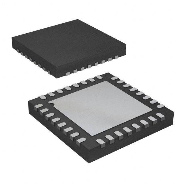
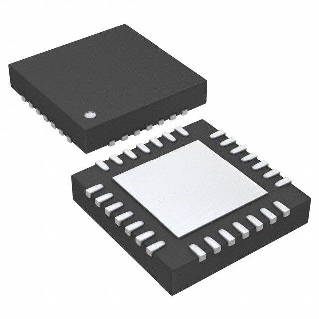
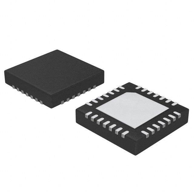
| 产品图片 |
|
| rohs | 符合RoHS无铅 / 符合限制有害物质指令(RoHS)规范要求 |
| 产品系列 | 接口 IC,接口—CODEC,Texas Instruments TP3057N/NOPB- |
| 数据手册 | |
| 产品型号 | TP3057N/NOPB |
| PCN设计/规格 | |
| 三角积分 | 无 |
| 产品种类 | 接口—CODEC |
| 供应商器件封装 | 16-PDIP |
| 信噪比,ADC/DAC(db)(典型值) | - |
| 其它名称 | *TP3057N/NOPB |
| 分辨率 | 8 bit |
| 分辨率(位) | - |
| 动态范围,ADC/DAC(db)(典型值) | - |
| 包装 | 管件 |
| 商标 | Texas Instruments |
| 安装类型 | 通孔 |
| 安装风格 | Through Hole |
| 封装 | Tube |
| 封装/外壳 | 16-DIP(0.300",7.62mm) |
| 封装/箱体 | PDIP-16 |
| 工作温度 | -25°C ~ 125°C |
| 工作电源电压 | +/- 5 V |
| 工厂包装数量 | 25 |
| 接口类型 | Serial |
| 数据接口 | 串行 |
| 最大工作温度 | + 125 C |
| 最小工作温度 | - 25 C |
| 标准包装 | 25 |
| 电压-电源,数字 | ±5V |
| 电压-电源,模拟 | ±5V |
| 电源电流 | 5 mA |
| 类型 | PCM, 滤波器 |
| 系列 | TP3057 |


_renders/CS4265-CNZR.jpg)

PDF Datasheet 数据手册内容提取
TP3054. TP3057 Enhanced Serial Interface CODEC/Filter COMBO Family Literature Number: SNAS569
T P August1994 3 0 5 4 (cid:44) TP3054(cid:44) TP3057 T P ‘‘Enhanced’’ Serial Interface 3 0 CODEC(cid:47)Filter COMBO(cid:201) Family 5 7 ‘ ‘ GeneralDescription Features E n The TP3054(cid:44) TP3057 family consists of m-law and A-law Y CompleteCODECandfilteringsystem(COMBO) h monolithic PCM CODEC(cid:47)filters utilizing the A(cid:47)D and D(cid:47)A including(cid:58) a conversionarchitectureshowninFigure1(cid:44)andaserialPCM (cid:208)Transmithigh-passandlow-passfiltering n interface(cid:46) The devices are fabricated using National’s ad- (cid:208)Receivelow-passfilterwithsinx(cid:47)xcorrection c vanceddouble-polyCMOSprocess(microCMOS)(cid:46) (cid:208)ActiveRCnoisefilters e d Theencodeportionofeachdeviceconsistsofaninputgain (cid:208)m-laworA-lawcompatibleCOderandDECoder ’ ahbdiagjnhuds-ftrpeaaqmsuspelfniiflicteeyrr(cid:44)ntahonaistaercetpjievriecotrRstCsoigpenrneat-lesfirlibtneegrlowawhsi2cw0hit0echHlimezdian-cnaadtepasabcvoietvoreyr (cid:208)(cid:208)(cid:208)ISInnetteerirrannlaaIll(cid:47)Opaureitnoct-ieszireofranocvecoirlctaugiteryreference ’Ser 3400Hz(cid:46)Alsoincludedareauto-zerocircuitryandacom- Y m-law(cid:44)16-pin(cid:208)TP3054 ia panding coder which samples the filtered signal and en- Y A-law(cid:44)16-pin(cid:208)TP3057 l codesitinthecompandedm-laworA-lawPCMformat(cid:46)The Y DesignedforD3(cid:47)D4andCCITTapplications In decode portion of each device consists of an expanding Y g5Voperation t decoder(cid:44) which reconstructs the analog signal from the Y Lowoperatingpower(cid:208)typically50mW e companded m-law or A-law code(cid:44) a low-pass filter which Y Power-downstandbymode(cid:208)typically3mW rf correctsforthesinx(cid:47)xresponseofthedecoderoutputand a rejectssignalsabove3400Hzfollowedbyasingle-ended Y Automaticpower-down c Y TTLorCMOScompatibledigitalinterfaces e power amplifier capable of driving low impedance loads(cid:46) The devices require two 1(cid:46)536 MHz(cid:44) 1(cid:46)544 MHz or 2(cid:46)048 Y Maximizeslineinterfacecardcircuitdensity C MHz transmit and receive master clocks(cid:44) which may be Y Dual-In-Lineorsurfacemountpackages O asynchronous(cid:59)transmitandreceivebitclocks(cid:44)whichmay Y See also AN-370(cid:44) ‘‘Techniques for Designing with D varyfrom64kHzto2(cid:46)048MHz(cid:59)andtransmitandreceive CODEC(cid:47)FilterCOMBOCircuits’’ E framesyncpulses(cid:46)Thetimingoftheframesyncpulsesand C PCMdataiscompatiblewithbothindustrystandardformats(cid:46) (cid:47) F i ConnectionDiagrams lt e r Dual-In-LinePackage PlasticChipCarriers C O M B O F a m i l y TL(cid:47)H(cid:47)5510–1 TopView OrderNumberTP3054JorTP3057J TL(cid:47)H(cid:47)5510–10 SeeNSPackageNumberJ16A TopView OrderNumberTP3054NorTP3057N OrderNumberTP3057V SeeNSPackageNumberN16A SeeNSPackageNumberV20A OrderNumberTP3054WMorTP3057WM SeeNSPackageNumberM16B COMBO(cid:201)andTRI-STATE(cid:201)areregisteredtrademarksofNationalSemiconductorCorporation(cid:46) C1995NationalSemiconductorCorporation TL(cid:47)H(cid:47)5510 RRD-B30M125(cid:47)PrintedinU(cid:46)S(cid:46)A(cid:46)
BlockDiagram FIGURE1 TL(cid:47)H(cid:47)5510–2 PinDescription Symbol Function Symbol Function VBB Negativepowersupplypin(cid:46) shouldbesynchronouswithMCLKXforbestper- VBBeb5Vg5%(cid:46) formance(cid:46) When MCLKR is connected continu- GNDA Analogground(cid:46)Allsignalsarereferenced ouslylow(cid:44)MCLKXisselectedforallinternaltim- tothispin(cid:46) ing(cid:46) When MCLKR is connected continuously high(cid:44)thedeviceispowereddown(cid:46) VFRO Analogoutputofthereceivepowerampli- fier(cid:46) MCLKX Transmit master clock(cid:46) Must be 1(cid:46)536 MHz(cid:44) 1(cid:46)544MHzor2(cid:46)048MHz(cid:46)Maybeasynchronous VCC PVoCsCitieveapo5wVegrs5u%pp(cid:46)lypin(cid:46) swyitnhchMroCnLoKuRs(cid:46)oBpeesrtatpioenrf(cid:46)ormanceisrealizedfrom FSR aRBnCecL8eKkivRHeztofprasumhlsiefetsPtryCaniMnc(cid:46)pdSuaeltseaeFiniwgtuohriceDhsR2e(cid:46)nFaaSnbRdle3iss FSX TBrCaLnKsmXittofrsahmifteosuytntchepuPlsCeMindpauttawohnicDhX(cid:46)enFaSbXleiss an 8 kHz pulse train(cid:44) seeFigures2and3for fortimingdetails(cid:46) timingdetails(cid:46) DR RinetoceDivRefodlalotawiningputht(cid:46)ePFCSMRldeaatdainigsesdhgifete(cid:46)d BCLKX TDhXe(cid:46) Mbiatyclovackrywfhroicmh6sh4iftksHozuttoth2e(cid:46)0P4C8MMdHazt(cid:44)abount BCLKR(cid:47)CLKSEL ThebitclockwhichshiftsdataintoDRaf- mustbesynchronouswithMCLKX(cid:46) 6te4rkthHezFtoSR2(cid:46)l0e4a8dinMgHezd(cid:46)gAel(cid:46)teMrnaaytivvealryy(cid:44)fmroamy DX TheTRI-STATE(cid:201)PCMdataoutputwhichisen- be a logic input which selects either abledbyFSX(cid:46) 1(cid:46)536MHz(cid:47)1(cid:46)544MHzor2(cid:46)048MHzfor TSX Open drain output which pulses low during the master clock in synchronous mode and encodertimeslot(cid:46) BCLKXisusedforbothtransmitandre- GSX Analog output of the transmit input amplifier(cid:46) ceivedirections(seeTableI)(cid:46) Usedtoexternallysetgain(cid:46) MCLKR(cid:47)PDN Receive master clock(cid:46) Must be VFXIb Invertinginputofthetransmitinputamplifier(cid:46) 1(cid:46)536 MHz(cid:44) 1(cid:46)544 MHz or 2(cid:46)048 MHz(cid:46) VFXIa Non-invertinginputofthetransmitinputamplifi- May be asynchronous with MCLKX(cid:44) but er(cid:46) 2
FunctionalDescription POWER-UP ASYNCHRONOUSOPERATION Whenpowerisfirstapplied(cid:44)power-onresetcircuitryinitializ- Forasynchronousoperation(cid:44)separatetransmitandreceive estheCOMBOandplacesitintoapower-downstate(cid:46)All clocks may be applied(cid:46) MCLKX and MCLKR must be non-essentialcircuitsaredeactivatedandtheDXandVFRO 2(cid:46)048MHzfortheTP3057(cid:44)or1(cid:46)536MHz(cid:44)1(cid:46)544MHzforthe outputsareputinhighimpedancestates(cid:46)Topower-upthe TP3054(cid:44)andneednotbesynchronous(cid:46)Forbesttransmis- device(cid:44)alogicallowlevelorclockmustbeappliedtothe sionperformance(cid:44)however(cid:44)MCLKRshouldbesynchronous MCLKR(cid:47)PDNpinandFSXand(cid:47)orFSRpulsesmustbepres- withMCLKX(cid:44)whichiseasilyachievedbyapplyingonlystatic ent(cid:46)Thus(cid:44)2power-downcontrolmodesareavailable(cid:46)The logiclevelstotheMCLKR(cid:47)PDNpin(cid:46)Thiswillautomatically firstistopulltheMCLKR(cid:47)PDNpinhigh(cid:59)thealternativeisto connect MCLKX to all internal MCLKR functions (see Pin holdbothFSXandFSRinputscontinuouslylow(cid:208)thedevice Description)(cid:46)For1(cid:46)544MHzoperation(cid:44)thedeviceautomati- willpower-downapproximately1msafterthelastFSXor cally compensates for the 193rd clock pulse each frame(cid:46) FSR pulse(cid:46) Power-up will occur on the first FSX or FSR FSXstartseachencodingcycleandmustbesynchronous pulse(cid:46)TheTRI-STATEPCMdataoutput(cid:44)DX(cid:44)willremainin with MCLKX and BCLKX(cid:46) FSR starts each decoding cycle thehighimpedancestateuntilthesecondFSXpulse(cid:46) andmustbesynchronouswithBCLKR(cid:46)BCLKRmustbea clock(cid:44) the logic levels shown in Table 1 are not valid in SYNCHRONOUSOPERATION asynchronousmode(cid:46)BCLKXandBCLKRmayoperatefrom Forsynchronousoperation(cid:44)thesamemasterclockandbit 64kHzto2(cid:46)048MHz(cid:46) clockshouldbeusedforboththetransmitandreceivedi- rections(cid:46)Inthismode(cid:44)aclockmustbeappliedtoMCLKX SHORTFRAMESYNCOPERATION and the MCLKR(cid:47)PDN pin can be used as a power-down TheCOMBOcanutilizeeitherashortframesyncpulseora control(cid:46)AlowlevelonMCLKR(cid:47)PDNpowersupthedevice longframesyncpulse(cid:46)Uponpowerinitialization(cid:44)thedevice and a high level powers down the device(cid:46) In either case(cid:44) assumesashortframemode(cid:46)Inthismode(cid:44)bothframesync MCLKX will be selected as the master clock for both the pulses(cid:44) FSX and FSR(cid:44) must be one bit clock period long(cid:44) transmitandreceivecircuits(cid:46)Abitclockmustalsobeap- withtimingrelationshipsspecifiedinFigure2(cid:46)WithFSXhigh plied to BCLKX and the BCLKR(cid:47)CLKSEL can be used to during a falling edge of BCLKX(cid:44) the next rising edge of selecttheproperinternaldividerforamasterclockof1(cid:46)536 BCLKXenablestheDXTRI-STATEoutputbuffer(cid:44)whichwill MHz(cid:44)1(cid:46)544MHzor2(cid:46)048MHz(cid:46)For1(cid:46)544MHzoperation(cid:44) outputthesignbit(cid:46)Thefollowingsevenrisingedgesclock thedeviceautomaticallycompensatesforthe193rdclock outtheremainingsevenbits(cid:44)andthenextfallingedgedis- pulseeachframe(cid:46) ablestheDXoutput(cid:46)WithFSRhighduringafallingedgeof WithafixedlevelontheBCLKR(cid:47)CLKSELpin(cid:44)BCLKXwillbe BCLKR(BCLKXinsynchronousmode)(cid:44)thenextfallingedge selectedasthebitclockforboththetransmitandreceive ofBCLKRlatchesinthesignbit(cid:46)Thefollowingsevenfalling directions(cid:46) Table 1 indicates the frequencies of operation edges latch in the seven remaining bits(cid:46) All four devices whichcanbeselected(cid:44)dependingonthestateofBCLKR(cid:47) may utilize the short frame sync pulse in synchronous or CLKSEL(cid:46)Inthissynchronousmode(cid:44)thebitclock(cid:44)BCLKX(cid:44) asynchronousoperatingmode(cid:46) maybefrom64kHzto2(cid:46)048MHz(cid:44)butmustbesynchro- LONGFRAMESYNCOPERATION nouswithMCLKX(cid:46) Tousethelongframemode(cid:44)boththeframesyncpulses(cid:44) Each FSX pulse begins the encoding cycle and the PCM FSXandFSR(cid:44)mustbethreeormorebitclockperiodslong(cid:44) data from the previous encode cycle is shifted out of the withtimingrelationshipsspecifiedinFigure3(cid:46)Basedonthe enabledDXoutputonthepositiveedgeofBCLKX(cid:46)After8 transmitframesync(cid:44)FSX(cid:44)theCOMBOwillsensewhether bitclockperiods(cid:44)theTRI-STATEDXoutputisreturnedtoa shortorlongframesyncpulsesarebeingused(cid:46)For64kHz high impedance state(cid:46) With an FSR pulse(cid:44) PCM data is operation(cid:44)theframesyncpulsemustbekeptlowforamini- latchedviatheDRinputonthenegativeedgeofBCLKX(or mumof160ns(cid:46)TheDXTRI-STATEoutputbufferisenabled BCLKRifrunning)(cid:46)FSXandFSRmustbesynchronouswith with the rising edge of FSX or the rising edge of BCLKX(cid:44) MCLKX(cid:47)R(cid:46) whichevercomeslater(cid:44)andthefirstbitclockedoutisthe TABLEI(cid:46)SelectionofMasterClockFrequencies signbit(cid:46)ThefollowingsevenBCLKXrisingedgesclockout theremainingsevenbits(cid:46)TheDXoutputisdisabledbythe MasterClock fallingBCLKXedgefollowingtheeighthrisingedge(cid:44)orby BCLKR(cid:47)CLKSEL FrequencySelected FSXgoinglow(cid:44)whichevercomeslater(cid:46)Arisingedgeonthe TP3057 TP3054 receiveframesyncpulse(cid:44)FSR(cid:44)willcausethePCMdataat DRtobelatchedinonthenexteightfallingedgesofBCLKR Clocked 2(cid:46)048MHz 1(cid:46)536MHzor (BCLKXinsynchronousmode)(cid:46)Allfourdevicesmayutilize 1(cid:46)544MHz thelongframesyncpulseinsynchronousorasynchronous 0 1(cid:46)536MHzor 2(cid:46)048MHz mode(cid:46) 1(cid:46)544MHz InapplicationswheretheLSBbitisusedforsignallingwith 1 2(cid:46)048MHz 1(cid:46)536MHzor FSRtwobitclockperiodslong(cid:44)thedecoderwillinterpretthe lostLSBas‘‘(cid:40)(cid:47)(cid:50)’’tominimizenoiseanddistortion(cid:46) 1(cid:46)544MHz 3
FunctionalDescription (Continued) TRANSMITSECTION (due to encoding delay)(cid:44) which totals 290 ms(cid:46) Any offset The transmit section input is an operational amplifier with voltageduetothefiltersorcomparatoriscancelledbysign provisionforgainadjustmentusingtwoexternalresistors(cid:44) bitintegration(cid:46) seeFigure4(cid:46)Thelownoiseandwidebandwidthallowgains RECEIVESECTION inexcessof20dBacrosstheaudiopassbandtobereal- The receive section consists of an expanding DAC which ized(cid:46)Theopampdrivesaunity-gainfilterconsistingofRC drives a fifth order switched-capacitor low pass filter active pre-filter(cid:44) followed by an eighth order switched-ca- clocked at 256 kHz(cid:46) The decoder is A-law (TP3057) or pacitor bandpass filter clocked at 256 kHz(cid:46) Theoutputof m-law(TP3054)andthe5thorderlowpassfiltercorrectsfor thisfilterdirectlydrivestheencodersample-and-holdcircuit(cid:46) thesinx(cid:47)xattenuationduetothe8kHzsample(cid:47)hold(cid:46)The The A(cid:47)D is of companding type according to m-law filteristhenfollowedbya2ndorderRCactivepost-filter(cid:47) (TP3054) or A-law (TP3057) coding conventions(cid:46) A preci- poweramplifercapableofdrivinga600Xloadtoalevelof sionvoltagereferenceistrimmedinmanufacturingtopro- 7(cid:46)2dBm(cid:46)Thereceivesectionisunity-gain(cid:46)Upontheoccur- tpvaiudblesleeaocnfoTinnrtpraounltssmothviseesrsliooaanmdCp(hltinMagrAaXoc)ftetohrfiesntifcoilstme)(cid:46)irnToahulletypFu2tS(cid:46)(cid:44)5XaVnfrpdaemtahekens(sytehneec rfaelnlicnegoefdFgSeRo(cid:44)fththeednaetaxtateitghhetDBRCLinKpRut(iBsCcLloKcXk)epdeirnioodns(cid:46)thAet theendofthedecodertimeslot(cid:44)thedecodingcyclebegins(cid:44) successive-approximationencodingcyclebegins(cid:46)The8-bit and 10 ms later the decoder DAC output is updated(cid:46) The codeisthenloadedintoabufferandshiftedoutthroughDX total decoder delay is E 10 ms (decoder update) plus atthenextFSXpulse(cid:46)Thetotalencodingdelaywillbeap- 110 ms (filter delay) plus 62(cid:46)5 ms ((cid:40)(cid:47)(cid:50) frame)(cid:44) which gives proximately165ms(duetothetransmitfilter)plus125ms approximately180ms(cid:46) 4
AbsoluteMaximumRatings If Military(cid:47)Aerospace specified devices are required(cid:44) VoltageatanyDigitalInputor please contact the National Semiconductor Sales Output VCCa0(cid:46)3VtoGNDAb0(cid:46)3V Office(cid:47)Distributorsforavailabilityandspecifications(cid:46) OperatingTemperatureRange b25(cid:167)Ctoa125(cid:167)C VCCtoGNDA 7V StorageTemperatureRange b65(cid:167)Ctoa150(cid:167)C VBBtoGNDA b7V LeadTemperature(Soldering(cid:44)10seconds) 300(cid:167)C VoltageatanyAnalogInput ESD(HumanBodyModel) 2000V orOutput VCCa0(cid:46)3VtoVBBb0(cid:46)3V Latch-UpImmunitye100mAonanyPin Electrical Characteristics Unlessotherwisenoted(cid:44)limitsprintedinBOLDcharactersareguaranteedforVCC e5(cid:46)0Vg5%(cid:44)VBBeb5(cid:46)0Vg5%(cid:59)TAe0(cid:167)Cto70(cid:167)Cbycorrelationwith100%electricaltestingatTAe25(cid:167)C(cid:46)Allotherlimits areassuredbycorrelationwithotherproductiontestsand(cid:47)orproductdesignandcharacterization(cid:46)Allsignalsreferencedto GNDA(cid:46)TypicalsspecifiedatVCCe5(cid:46)0V(cid:44)VBBeb5(cid:46)0V(cid:44)TAe25(cid:167)C(cid:46) Symbol Parameter Conditions Min Typ Max Units DIGITALINTERFACE VIL InputLowVoltage 0(cid:46)6 V VIH InputHighVoltage 2(cid:46)2 V VOL OutputLowVoltage DX(cid:44)ILe3(cid:46)2mA 0(cid:46)4 V SIGR(cid:44)ILe1(cid:46)0mA 0(cid:46)4 V TSX(cid:44)ILe3(cid:46)2mA(cid:44)OpenDrain 0(cid:46)4 V VOH OutputHighVoltage DX(cid:44)IHeb3(cid:46)2mA 2(cid:46)4 V SIGR(cid:44)IHeb1(cid:46)0mA 2(cid:46)4 V IIL InputLowCurrent GNDAsVINsVIL(cid:44)AllDigitalInputs b10 10 mA IIH InputHighCurrent VIHsVINsVCC b10 10 mA IOZ OutputCurrentinHighImpedance DX(cid:44)GNDAsVOsVCC b10 10 mA State(TRI-STATE) ANALOGINTERFACEWITHTRANSMITINPUTAMPLIFIER(ALLDEVICES) IIXA InputLeakageCurrent b2(cid:46)5VsVsa2(cid:46)5V(cid:44)VFXIaorVFXIb b200 200 nA RIXA InputResistance b2(cid:46)5VsVsa2(cid:46)5V(cid:44)VFXIaorVFXIb 10 MX ROXA OutputResistance ClosedLoop(cid:44)UnityGain 1 3 X RLXA LoadResistance GSX 10 kX CLXA LoadCapacitance GSX 50 pF VOXA OutputDynamicRange GSX(cid:44)RLt10kX b2(cid:46)8 2(cid:46)8 V AVXA VoltageGain VFXIatoGSX 5000 V(cid:47)V FUXA UnityGainBandwidth 1 2 MHz VOSXA OffsetVoltage b20 20 mV VCMXA Common-ModeVoltage CMRRXAl60dB b2(cid:46)5 2(cid:46)5 V CMRRXA Common-ModeRejectionRatio DCTest 60 dB PSRRXA PowerSupplyRejectionRatio DCTest 60 dB ANALOGINTERFACEWITHRECEIVEFILTER(ALLDEVICES) RORF OutputResistance PinVFRO 1 3 X RLRF LoadResistance VFROeg2(cid:46)5V 600 X CLRF LoadCapacitance 500 pF VOSRO OutputDCOffsetVoltage b200 200 mV POWERDISSIPATION(ALLDEVICES) ICC0 Power-DownCurrent NoLoad(Note) 0(cid:46)5 1(cid:46)5 mA IBB0 Power-DownCurrent NoLoad(Note) 0(cid:46)05 0(cid:46)3 mA ICC1 Power-UpActiveCurrent NoLoad 5(cid:46)0 9(cid:46)0 mA IBB1 Power-UpActiveCurrent NoLoad 5(cid:46)0 9(cid:46)0 mA Note(cid:58)ICC0andIBB0aremeasuredafterfirstachievingapower-upstate(cid:46) 5
TimingSpecificationsUnlessotherwisenoted(cid:44)limitsprintedinBOLDcharactersareguaranteedforVCCe 5(cid:46)0Vg5%(cid:44)VBBeb5(cid:46)0Vg5%(cid:59)TAe0(cid:167)Cto70(cid:167)Cbycorrelationwith100%electricaltestingatTAe25(cid:167)C(cid:46)Allotherlimitsare assuredbycorrelationwithotherproductiontestsand(cid:47)orproductdesignandcharacterization(cid:46)AllsignalsreferencedtoGNDA(cid:46) TypicalsspecifiedatVCCe5(cid:46)0V(cid:44)VBBeb5(cid:46)0V(cid:44)TAe25(cid:167)C(cid:46)AlltimingparametersaremeasuredatVOHe2(cid:46)0VandVOLe 0(cid:46)7V(cid:46)SeeDefinitionsandTimingConventionssectionfortestmethodsinformation(cid:46) Symbol Parameter Conditions Min Typ Max Units 1(cid:47)tPM FrequencyofMasterClocks DependsontheDeviceUsedandthe 1(cid:46)536 MHz BCLKR(cid:47)CLKSELPin(cid:46) 1(cid:46)544 MHz MCLKXandMCLKR 2(cid:46)048 MHz tRM RiseTimeofMasterClock MCLKXandMCLKR 50 ns tFM FallTimeofMasterClock MCLKXandMCLKR 50 ns tPB PeriodofBitClock 485 488 15725 ns tRB RiseTimeofBitClock BCLKXandBCLKR 50 ns tFB FallTimeofBitClock BCLKXandBCLKR 50 ns tWMH WidthofMasterClockHigh MCLKXandMCLKR 160 ns tWML WidthofMasterClockLow MCLKXandMCLKR 160 ns tSBFM Set-UpTimefromBCLKXHigh FirstBitClockaftertheLeading 100 ns toMCLKXFallingEdge EdgeofFSX tSFFM Set-UpTimefromFSXHigh LongFrameOnly 100 ns toMCLKXFallingEdge tWBH WidthofBitClockHigh VIHe2(cid:46)2V 160 ns tWBL WidthofBitClockLow VILe0(cid:46)6V 160 ns tHBFL HoldingTimefromBitClock LongFrameOnly 0 ns LowtoFrameSync tHBFS HoldingTimefromBitClock ShortFrameOnly 0 ns HightoFrameSync tSFB Set-UpTimefromFrameSync LongFrameOnly 80 ns toBitClockLow tDBD DelayTimefromBCLKXHigh Loade150pFplus2LSTTLLoads 0 140 ns toDataValid tDBTS DelayTimetoTSXLow Loade150pFplus2LSTTLLoads 140 ns tDZC DelayTimefromBCLKXLowto CLe0pFto150pF 50 165 ns DataOutputDisabled tDZF DelayTimetoValidDatafrom CLe0pFto150pF 20 165 ns FSXorBCLKX(cid:44)Whichever ComesLater tSDB Set-UpTimefromDRValidto 50 ns BCLKR(cid:47)XLow tHBD HoldTimefromBCLKR(cid:47)XLowto 50 ns DRInvalid tSF Set-UpTimefromFSX(cid:47)Rto ShortFrameSyncPulse(1BitClock 50 ns BCLKX(cid:47)RLow PeriodLong) tHF HoldTimefromBCLKX(cid:47)RLow ShortFrameSyncPulse(1BitClock 100 ns toFSX(cid:47)RLow PeriodLong) tHBFl HoldTimefrom3rdPeriodof LongFrameSyncPulse(from3to8Bit 100 ns BitClockLowtoFrameSync ClockPeriodsLong) (FSXorFSR) tWFL MinimumWidthoftheFrame 64kBit(cid:47)sOperatingMode 160 ns SyncPulse(LowLevel) 6
TimingDiagrams 3 H(cid:47)5510– TL(cid:47) g n mi Ti c n y S e m a Fr ort h S 2(cid:46) E R U G FI 7
TimingDiagrams (Continued) 4 H(cid:47)5510– TL(cid:47) g n mi Ti c n y S e m a Fr g n o L 3(cid:46) E R U G FI 8
TransmissionCharacteristicsUnlessotherwisenoted(cid:44)limitsprintedinBOLDcharactersareguaranteedfor VCCe5(cid:46)0Vg5%(cid:44)VBBeb5(cid:46)0Vg5%(cid:59)TAe0(cid:167)Cto70(cid:167)Cbycorrelationwith100%electricaltestingatTAe25(cid:167)C(cid:46)Allother limitsareassuredbycorrelationwithotherproductiontestsand(cid:47)orproductdesignandcharacterization(cid:46)GNDAe0V(cid:44)fe 1(cid:46)02kHz(cid:44)VINe0dBm0(cid:44)transmitinputamplifierconnectedforunitygainnon-inverting(cid:46)TypicalsspecifiedatVCCe5(cid:46)0V(cid:44)VBB eb5(cid:46)0V(cid:44)TAe25(cid:167)C(cid:46) Symbol Parameter Conditions Min Typ Max Units AMPLITUDERESPONSE AbsoluteLevels Nominal0dBm0Levelis4dBm (DefinitionofNominalGain) (600X) 0dBm0 1(cid:46)2276 Vrms tMAX VirtualDecisionValveDefined MaxOverloadLevel PerCCITTRec(cid:46)G711 TP3054(3(cid:46)17dBm0) 2(cid:46)501 VPK TP3057(3(cid:46)14dBm0) 2(cid:46)492 VPK GXA TransmitGain(cid:44)Absolute TAe25(cid:167)C(cid:44)VCCe5V(cid:44)VBBeb5V InputatGSXe0dBm0at1020Hz TP3054(cid:47)57 b0(cid:46)15 0(cid:46)15 dB GXR TransmitGain(cid:44)RelativetoGXA fe16Hz b40 dB fe50Hz b30 dB fe60Hz b26 dB fe200Hz b1(cid:46)8 b0(cid:46)1 dB fe300Hzb3000Hz b0(cid:46)15 0(cid:46)15 dB fe3300Hz b0(cid:46)35 0(cid:46)05 dB fe3400Hz b0(cid:46)7 0 dB fe4000Hz b14 dB fe4600HzandUp(cid:44)Measure b32 dB Responsefrom0Hzto4000Hz GXAT AbsoluteTransmitGainVariation RelativetoGXA b0(cid:46)1 0(cid:46)1 dB withTemperature GXAV AbsoluteTransmitGainVariation RelativetoGXA b0(cid:46)05 0(cid:46)05 dB withSupplyVoltage GXRL TransmitGainVariationswith SinusoidalTestMethod Level ReferenceLeveleb10dBm0 VFXIaeb40dBm0toa3dBm0 b0(cid:46)2 0(cid:46)2 dB VFXIaeb50dBm0tob40dBm0 b0(cid:46)4 0(cid:46)4 dB VFXIaeb55dBm0tob50dBm0 b1(cid:46)2 1(cid:46)2 dB GRA ReceiveGain(cid:44)Absolute TAe25(cid:167)C(cid:44)VCCe5V(cid:44)VBBeb5V InputeDigitalCodeSequencefor 0dBm0Signalat1020Hz TP3054(cid:47)57 b0(cid:46)15 0(cid:46)15 dB GRR ReceiveGain(cid:44)RelativetoGRA fe0Hzto3000Hz b0(cid:46)15 0(cid:46)15 dB fe3300Hz b0(cid:46)35 0(cid:46)05 dB fe3400Hz b0(cid:46)7 0 dB fe4000Hz b14 dB GRAT AbsoluteReceiveGainVariation RelativetoGRA b0(cid:46)1 0(cid:46)1 dB withTemperature GRAV AbsoluteReceiveGainVariation RelativetoGRA b0(cid:46)05 0(cid:46)05 dB withSupplyVoltage GRRL ReceiveGainVariationswith SinusoidalTestMethod(cid:59)Reference Level InputPCMCodeCorrespondstoan IdeallyEncodedPCMLevel eb40dBm0toa3dBm0 b0(cid:46)2 0(cid:46)2 dB eb50dBm0tob40dBm0 b0(cid:46)4 0(cid:46)4 dB eb55dBm0tob50dBm0 b1(cid:46)2 1(cid:46)2 dB VRO ReceiveOutputDriveLevel RLe600X b2(cid:46)5 2(cid:46)5 V 9
TransmissionCharacteristics (Continued)Unlessotherwisenoted(cid:44)limitsprintedinBOLDcharactersare guaranteedforVCCe5(cid:46)0Vg5%(cid:44)VBBeb5(cid:46)0Vg5%(cid:59)TAe0(cid:167)Cto70(cid:167)Cbycorrelationwith100%electricaltestingatTAe 25(cid:167)C(cid:46)Allotherlimitsareassuredbycorrelationwithotherproductiontestsand(cid:47)orproductdesignandcharacterization(cid:46)GNDA e0V(cid:44)fe1(cid:46)02kHz(cid:44)VINe0dBm0(cid:44)transmitinputamplifierconnectedforunitygainnon-inverting(cid:46)TypicalsspecifiedatVCCe 5(cid:46)0V(cid:44)VBBeb5(cid:46)0V(cid:44)TAe25(cid:167)C(cid:46) Symbol Parameter Conditions Min Typ Max Units ENVELOPEDELAYDISTORTIONWITHFREQUENCY DXA TransmitDelay(cid:44)Absolute fe1600Hz 290 315 ms DXR TransmitDelay(cid:44)RelativetoDXA fe500Hz–600Hz 195 220 ms fe600Hz–800Hz 120 145 ms fe800Hz–1000Hz 50 75 ms fe1000Hz–1600Hz 20 40 ms fe1600Hz–2600Hz 55 75 ms fe2600Hz–2800Hz 80 105 ms fe2800Hz–3000Hz 130 155 ms DRA ReceiveDelay(cid:44)Absolute fe1600Hz 180 200 ms DRR ReceiveDelay(cid:44)RelativetoDRA fe500Hz–1000Hz b40 b25 ms fe1000Hz–1600Hz b30 b20 ms fe1600Hz–2600Hz 70 90 ms fe2600Hz–2800Hz 100 125 ms fe2800Hz–3000Hz 145 175 ms NOISE NXC TransmitNoise(cid:44)CMessage TP3054 12 15 dBrnC0 Weighted NXP TransmitNoise(cid:44)PMessage TP3057 b74 b67 dBm0p Weighted NRC ReceiveNoise(cid:44)CMessage PCMCodeisAlternatingPositive Weighted andNegativeZero(cid:208)TP3054 8 11 dBrnC0 NRP ReceiveNoise(cid:44)PMessage PCMCodeEqualsPositive Weighted Zero(cid:208)TP3057 b82 b79 dBm0p NRS Noise(cid:44)SingleFrequency fe0kHzto100kHz(cid:44)LoopAround b53 dBm0 Measurement(cid:44)VFXIae0Vrms PPSRX PositivePowerSupplyRejection(cid:44) VFXIaeb50dBm0 Transmit VCCe5(cid:46)0VDCa100mVrms fe0kHz–50kHz(Note2) 40 dBC NPSRX NegativePowerSupplyRejection(cid:44) VFXIaeb50dBm0 Transmit VBBeb5(cid:46)0VDCa100mVrms fe0kHz–50kHz(Note2) 40 dBC PPSRR PositivePowerSupplyRejection(cid:44) PCMCodeEqualsPositiveZero Receive VCCe5(cid:46)0VDCa100mVrms MeasureVFR0 fe0Hz–4000Hz 40 dBC fe4kHz–25kHz 40 dB fe25kHz–50kHz 36 dB NPSRR NegativePowerSupplyRejection(cid:44) PCMCodeEqualsPositiveZero Receive VBBeb5(cid:46)0VDCa100mVrms MeasureVFR0 fe0Hz–4000Hz 40 dBC fe4kHz–25kHz 40 dB fe25kHz–50kHz 36 dB 10
TransmissionCharacteristics (Continued)Unlessotherwisenoted(cid:44)limitsprintedinBOLDcharactersare guaranteedforVCCe5(cid:46)0Vg5%(cid:44)VBBeb5(cid:46)0Vg5%(cid:59)TAe0(cid:167)Cto70(cid:167)Cbycorrelationwith100%electricaltestingatTAe 25(cid:167)C(cid:46)Allotherlimitsareassuredbycorrelationwithotherproductiontestsand(cid:47)orproductdesignandcharacterization(cid:46)GNDA e0V(cid:44)fe1(cid:46)02kHz(cid:44)VINe0dBm0(cid:44)transmitinputamplifierconnectedforunitygainnon-inverting(cid:46)TypicalsspecifiedatVCCe 5(cid:46)0V(cid:44)VBBeb5(cid:46)0V(cid:44)TAe25(cid:167)C(cid:46) Symbol Parameter Conditions Min Typ Max Units SOS SpuriousOut-of-BandSignals LoopAroundMeasurement(cid:44)0dBm0(cid:44) b30 dB attheChannelOutput 300Hzto3400HzInputPCMCodeApplied atDR(cid:46) 4600Hz–7600Hz b30 dB 7600Hz–8400Hz b40 dB 8400Hz–100(cid:44)000Hz b30 dB DISTORTION STDX SignaltoTotalDistortion SinusoidalTestMethod(Note3) STDR TransmitorReceive Levele3(cid:46)0dBm0 33 dBC Half-Channel e0dBm0tob30dBm0 36 dBC eb40dBm0 XMT 29 dBC RCV 30 dBC eb55dBm0 XMT 14 dBC RCV 15 dBC SFDX SingleFrequencyDistortion(cid:44) b46 dB Transmit SFDR SingleFrequencyDistortion(cid:44) b46 dB Receive IMD IntermodulationDistortion LoopAroundMeasurement(cid:44) b41 dB VFXaeb4dBm0tob21dBm0(cid:44)Two FrequenciesintheRange 300Hz–3400Hz CROSSTALK CTX-R TransmittoReceiveCrosstalk(cid:44) fe300Hz–3400Hz 0dBm0TransmitLevel DReQuietPCMCode b90 b75 dB CTR-X ReceivetoTransmitCrosstalk(cid:44) fe300Hz–3400Hz(cid:44)VFXIeMultitone b90 b70 dB 0dBm0ReceiveLevel (Note2) ENCODINGFORMATATDXOUTPUT TP3057 TP3054 A-Law m-Law (IncludesEvenBitInversion) VIN(atGSX)eaFull-Scale 1 0 0 0 0 0 0 0 1 0 1 0 1 0 1 0 VIN(atGSX)e0V (cid:208)01 11 11 11 11 11 11 11 01 11 00 11 00 11 00 11 VIN(atGSX)ebFull-Scale 0 0 0 0 0 0 0 0 0 0 1 0 1 0 1 0 Note1(cid:58)Measuredbyextrapolationfromthedistortiontestresultatb50dBm0(cid:46) Note2(cid:58)PPSRX(cid:44)NPSRX(cid:44)andCTR-Xaremeasuredwithab50dBm0activationsignalappliedtoVFXIa(cid:46) Note3(cid:58)DevicesaremeasuredusingCmessageweightedfilterform-LawandpsophometricweightedfilterforA-Law(cid:46) 11
ApplicationsInformation POWERSUPPLIES While the pins of the TP305X family are well protected ThiscommongroundpointshouldbedecoupledtoVCCand againstelectricalmisuse(cid:44)itisrecommendedthatthestan- VBBwith10mFcapacitors(cid:46) dard CMOS practice be followed(cid:44) ensuring that ground is RECEIVEGAINADJUSTMENT connectedtothedevicebeforeanyotherconnectionsare made(cid:46)Inapplicationswheretheprintedcircuitboardmaybe For applications where a TP305X family CODEC(cid:47)filter re- pluggedintoa‘‘hot’’socketwithpowerandclocksalready ceiveoutputmustdrivea600Xload(cid:44)butapeakswinglower present(cid:44)anextralonggroundpinintheconnectorshould than g2(cid:46)5Visrequired(cid:44)thereceivegaincanbeeasilyad- beused(cid:46) justedbyinsertingamatchedT-padorq-padattheoutput(cid:46) TableIIliststherequiredresistorvaluesfor600Xtermina- All ground connections to each device should meet at a tions(cid:46)Asthesearegenerallynon-standardvalues(cid:44)theequa- commonpointascloseaspossibletotheGNDApin(cid:46)This tionscanbeusedtocomputetheattenuationoftheclosest minimizestheinteractionofgroundreturncurrentsflowing practical set of resistors(cid:46) It may be necessary to use un- throughacommonbusimpedance(cid:46)0(cid:46)1 mFsupplydecou- equal values for the R1 orR4armsoftheattenuatorsto pling capacitors should be connected from this common achieve a precise attenuation(cid:46) Generally it is tolerable to ground point to VCC and VBB(cid:44) as close to the device as allowasmalldeviationoftheinputimpedancefromnominal possible(cid:46) whilestillmaintainingagoodreturnloss(cid:46)Forexamplea30 Forbestperformance(cid:44)thegroundpointofeachCODEC(cid:47) dBreturnlossagainst600Xisobtainediftheoutputimped- FILTERonacardshouldbeconnectedtoacommoncard anceoftheattenuatorisintherange282Xto319X(as- groundinstarformation(cid:44)ratherthanviaagroundbus(cid:46) sumingaperfecttransformer)(cid:46) T-PadAttenuator R1eZ1(cid:35)NN22ba11Jb20Z1(cid:46)Z2(cid:35)N2Nb1J R2e20Z1(cid:46)Z2(cid:35)N2Nb1J Where(cid:58)Ne0POWERIN POWEROUT and Se0Z1 Z2 Also(cid:58)Ze0ZSC(cid:35)ZOC WhereZSCeimpedancewithshortcircuittermination andZOCeimpedancewithopencircuittermination q-PadAttenuator TL(cid:47)H(cid:47)5510–5 R3e0Z1(cid:46)Z2(cid:35)N2b1J 2 N R3eZ1(cid:35)N2bN22bNS1a1J Note(cid:58)SeeApplicationNote370forfurtherdetails(cid:46) 12
ApplicationsInformation (Continued) TABLEII(cid:46)AttentuatorTablesforZ1eZ2e300X (AllValuesinX) dB R1 R2 R3 R4 0(cid:46)1 1(cid:46)7 26k 3(cid:46)5 52k 0(cid:46)2 3(cid:46)5 13k 6(cid:46)9 26k 0(cid:46)3 5(cid:46)2 8(cid:46)7k 10(cid:46)4 17(cid:46)4k 0(cid:46)4 6(cid:46)9 6(cid:46)5k 13(cid:46)8 13k 0(cid:46)5 8(cid:46)5 5(cid:46)2k 17(cid:46)3 10(cid:46)5k 0(cid:46)6 10(cid:46)4 4(cid:46)4k 21(cid:46)3 8(cid:46)7k 0(cid:46)7 12(cid:46)1 3(cid:46)7k 24(cid:46)2 7(cid:46)5k 0(cid:46)8 13(cid:46)8 3(cid:46)3k 27(cid:46)7 6(cid:46)5k 0(cid:46)9 15(cid:46)5 2(cid:46)9k 31(cid:46)1 5(cid:46)8k 1(cid:46)0 17(cid:46)3 2(cid:46)6l 34(cid:46)6 5(cid:46)2k 2 34(cid:46)4 1(cid:46)3k 70 2(cid:46)6k 3 51(cid:46)3 850 107 1(cid:46)8k 4 68 650 144 1(cid:46)3k 5 84 494 183 1(cid:46)1k 6 100 402 224 900 7 115 380 269 785 8 379 284 317 698 9 143 244 370 630 10 156 211 427 527 11 168 184 490 535 12 180 161 550 500 13 190 142 635 473 14 200 125 720 450 15 210 110 816 430 16 218 98 924 413 18 233 77 1(cid:46)17k 386 20 246 61 1(cid:46)5k 366 TypicalSynchronousApplication TL(cid:47)H(cid:47)5510–6 Note1(cid:58)XMITgaine20clog(cid:35)R1aR2Jwhere(R1aR2)l10KX(cid:46) R2 FIGURE4 13
ConnectionDiagrams (Continued) PlasticChipCarrier TL(cid:47)H(cid:47)5510–7 TopView OrderNumberTP3057V SeeNSPackageNumberV20A 14
PhysicalDimensions inches(millimeters) CavityDual-In-LinePackage(J) OrderNumberTP3054JorTP3057J NSPackageNumberJ16A MoldedSmallOutlinePackage(WM) OrderNumberTP3054WMorTP3057WM NSPackageNumberM16B 15
y mil PhysicalDimensionsinches(millimeters)(Continued) a F O B M O C r e t l i F (cid:47) C E D O C e c a f r e t n I MoldedDual-In-LinePackage(N) l OrderNumberTP3054NorTP3057N a NSPackageNumberN16A i r e S ’ ’ d e c n a h n E ‘ ‘ 7 5 0 3 P T (cid:44) 4 5 LIFE SUPPORT POLICY 0 3 NATIONAL’S PRODUCTS ARE NOT AUTHORIZED FOR USE AS CRITICAL COMPONENTS IN LIFE SUPPORT P DEVICES OR SYSTEMS WITHOUT THE EXPRESS WRITTEN APPROVAL OF THE PRESIDENT OF NATIONAL T SEMICONDUCTORCORPORATION(cid:46)Asusedherein(cid:58) 1(cid:46) Life support devices or systems are devices or 2(cid:46) A critical component is any component of a life systems which(cid:44) (a) are intended for surgical implant supportdeviceorsystemwhosefailuretoperformcan intothebody(cid:44)or(b)supportorsustainlife(cid:44)andwhose bereasonablyexpectedtocausethefailureofthelife failure to perform(cid:44) when properly used in accordance support device or system(cid:44) or to affect its safety or with instructions for use provided in the labeling(cid:44) can effectiveness(cid:46) bereasonablyexpectedtoresultinasignificantinjury totheuser(cid:46) NationalSemiconductor NationalSemiconductor NationalSemiconductor NationalSemiconductor Corporation Europe HongKongLtd(cid:46) JapanLtd(cid:46) 1111WestBardinRoad Fax(cid:58)(a49)0-180-5308586 13thFloor(cid:44)StraightBlock(cid:44) Tel(cid:58) 81-043-299-2309 Arlington(cid:44)TX76017 Email(cid:58)cnjwge(cid:64)tevm2(cid:46)nsc(cid:46)com OceanCentre(cid:44)5CantonRd(cid:46) Fax(cid:58)81-043-299-2408 Tel(cid:58)1(800)272-9959 Deutsch Tel(cid:58)(a49)0-180-5308585 Tsimshatsui(cid:44)Kowloon Fax(cid:58)1(800)737-7018 English Tel(cid:58)(a49)0-180-5327832 HongKong Fran(cid:51)aisTel(cid:58)(a49)0-180-5329358 Tel(cid:58)(852)2737-1600 Italiano Tel(cid:58)(a49)0-180-5341680 Fax(cid:58)(852)2736-9960 Nationaldoesnotassumeanyresponsibilityforuseofanycircuitrydescribed(cid:44)nocircuitpatentlicensesareimpliedandNationalreservestherightatanytimewithoutnoticetochangesaidcircuitryandspecifications(cid:46)
IMPORTANTNOTICE TexasInstrumentsIncorporatedanditssubsidiaries(TI)reservetherighttomakecorrections,modifications,enhancements,improvements, andotherchangestoitsproductsandservicesatanytimeandtodiscontinueanyproductorservicewithoutnotice.Customersshould obtainthelatestrelevantinformationbeforeplacingordersandshouldverifythatsuchinformationiscurrentandcomplete.Allproductsare soldsubjecttoTI’stermsandconditionsofsalesuppliedatthetimeoforderacknowledgment. TIwarrantsperformanceofitshardwareproductstothespecificationsapplicableatthetimeofsaleinaccordancewithTI’sstandard warranty.TestingandotherqualitycontroltechniquesareusedtotheextentTIdeemsnecessarytosupportthiswarranty.Exceptwhere mandatedbygovernmentrequirements,testingofallparametersofeachproductisnotnecessarilyperformed. TIassumesnoliabilityforapplicationsassistanceorcustomerproductdesign.Customersareresponsiblefortheirproductsand applicationsusingTIcomponents.Tominimizetherisksassociatedwithcustomerproductsandapplications,customersshouldprovide adequatedesignandoperatingsafeguards. TIdoesnotwarrantorrepresentthatanylicense,eitherexpressorimplied,isgrantedunderanyTIpatentright,copyright,maskworkright, orotherTIintellectualpropertyrightrelatingtoanycombination,machine,orprocessinwhichTIproductsorservicesareused.Information publishedbyTIregardingthird-partyproductsorservicesdoesnotconstitutealicensefromTItousesuchproductsorservicesora warrantyorendorsementthereof.Useofsuchinformationmayrequirealicensefromathirdpartyunderthepatentsorotherintellectual propertyofthethirdparty,oralicensefromTIunderthepatentsorotherintellectualpropertyofTI. ReproductionofTIinformationinTIdatabooksordatasheetsispermissibleonlyifreproductioniswithoutalterationandisaccompanied byallassociatedwarranties,conditions,limitations,andnotices.Reproductionofthisinformationwithalterationisanunfairanddeceptive businesspractice.TIisnotresponsibleorliableforsuchaltereddocumentation.Informationofthirdpartiesmaybesubjecttoadditional restrictions. ResaleofTIproductsorserviceswithstatementsdifferentfromorbeyondtheparametersstatedbyTIforthatproductorservicevoidsall expressandanyimpliedwarrantiesfortheassociatedTIproductorserviceandisanunfairanddeceptivebusinesspractice.TIisnot responsibleorliableforanysuchstatements. TIproductsarenotauthorizedforuseinsafety-criticalapplications(suchaslifesupport)whereafailureoftheTIproductwouldreasonably beexpectedtocauseseverepersonalinjuryordeath,unlessofficersofthepartieshaveexecutedanagreementspecificallygoverning suchuse.Buyersrepresentthattheyhaveallnecessaryexpertiseinthesafetyandregulatoryramificationsoftheirapplications,and acknowledgeandagreethattheyaresolelyresponsibleforalllegal,regulatoryandsafety-relatedrequirementsconcerningtheirproducts andanyuseofTIproductsinsuchsafety-criticalapplications,notwithstandinganyapplications-relatedinformationorsupportthatmaybe providedbyTI.Further,BuyersmustfullyindemnifyTIanditsrepresentativesagainstanydamagesarisingoutoftheuseofTIproductsin suchsafety-criticalapplications. TIproductsareneitherdesignednorintendedforuseinmilitary/aerospaceapplicationsorenvironmentsunlesstheTIproductsare specificallydesignatedbyTIasmilitary-gradeor"enhancedplastic."OnlyproductsdesignatedbyTIasmilitary-grademeetmilitary specifications.BuyersacknowledgeandagreethatanysuchuseofTIproductswhichTIhasnotdesignatedasmilitary-gradeissolelyat theBuyer'srisk,andthattheyaresolelyresponsibleforcompliancewithalllegalandregulatoryrequirementsinconnectionwithsuchuse. TIproductsareneitherdesignednorintendedforuseinautomotiveapplicationsorenvironmentsunlessthespecificTIproductsare designatedbyTIascompliantwithISO/TS16949requirements.Buyersacknowledgeandagreethat,iftheyuseanynon-designated productsinautomotiveapplications,TIwillnotberesponsibleforanyfailuretomeetsuchrequirements. FollowingareURLswhereyoucanobtaininformationonotherTexasInstrumentsproductsandapplicationsolutions: Products Applications Audio www.ti.com/audio CommunicationsandTelecom www.ti.com/communications Amplifiers amplifier.ti.com ComputersandPeripherals www.ti.com/computers DataConverters dataconverter.ti.com ConsumerElectronics www.ti.com/consumer-apps DLP®Products www.dlp.com EnergyandLighting www.ti.com/energy DSP dsp.ti.com Industrial www.ti.com/industrial ClocksandTimers www.ti.com/clocks Medical www.ti.com/medical Interface interface.ti.com Security www.ti.com/security Logic logic.ti.com Space,AvionicsandDefense www.ti.com/space-avionics-defense PowerMgmt power.ti.com TransportationandAutomotive www.ti.com/automotive Microcontrollers microcontroller.ti.com VideoandImaging www.ti.com/video RFID www.ti-rfid.com OMAPMobileProcessors www.ti.com/omap WirelessConnectivity www.ti.com/wirelessconnectivity TIE2ECommunityHomePage e2e.ti.com MailingAddress:TexasInstruments,PostOfficeBox655303,Dallas,Texas75265 Copyright©2011,TexasInstrumentsIncorporated