ICGOO在线商城 > 电路保护 > TVS - 变阻器,MOV > TMOV14RP275E

 Datasheet下载
- 型号: TMOV14RP275E
- 制造商: Littelfuse
- 库位|库存: xxxx|xxxx
- 要求:
| 数量阶梯 | 香港交货 | 国内含税 |
| +xxxx | $xxxx | ¥xxxx |
查看当月历史价格
查看今年历史价格
TMOV14RP275E产品简介:
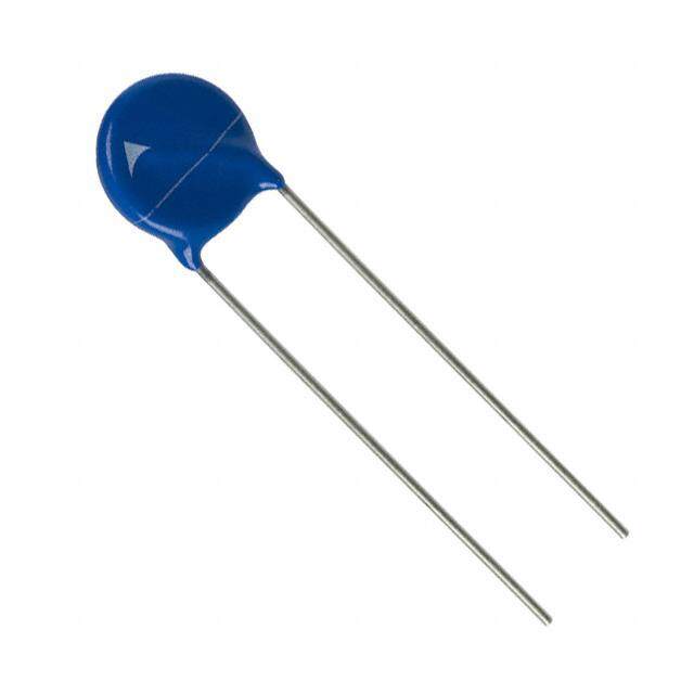
ICGOO电子元器件商城为您提供TMOV14RP275E由Littelfuse设计生产,在icgoo商城现货销售,并且可以通过原厂、代理商等渠道进行代购。 TMOV14RP275E价格参考。LittelfuseTMOV14RP275E封装/规格:TVS - 变阻器,MOV, 430V 6kA Varistor 1 Circuit Through Hole Disc 14mm。您可以下载TMOV14RP275E参考资料、Datasheet数据手册功能说明书,资料中有TMOV14RP275E 详细功能的应用电路图电压和使用方法及教程。
Littelfuse Inc. 的 TMOV14RP275E 是一款瞬态电压抑制器(TVS),属于金属氧化物变阻器(MOV)系列,主要用于保护电子设备免受瞬态过电压的损害。以下是该型号的应用场景:

 1. 电源线路保护
   - TMOV14RP275E 可用于交流或直流电源线路上,防止雷击、电涌或其他瞬态电压对电源系统造成破坏。
   - 典型应用包括家用电器(如空调、冰箱、洗衣机)、工业设备和电源适配器。

 2. 通信设备保护
   - 在通信接口中,例如电话线、网络线(以太网)或天线输入端,该器件可以吸收由于雷击或开关操作引起的瞬态电压。
   - 常见于调制解调器、路由器和无线基站等设备。

 3. 信号线路保护
   - 适用于低速或高速信号线路的过压保护,例如传感器信号线、控制信号线或数据传输线。
   - 能够有效保护微控制器、模拟电路和其他敏感元件。

 4. 汽车电子保护
   - 在汽车电子系统中,TMOV14RP275E 可用于保护车载电子设备免受负载突降、启动冲击或其他瞬态电压的影响。
   - 应用场景包括车载音响、导航系统、发动机控制单元(ECU)等。

 5. 工业自动化设备
   - 用于工业自动化控制系统中的电源和信号线路保护,防止因电涌或电磁干扰导致设备故障。
   - 例如可编程逻辑控制器(PLC)、变频器和伺服驱动器。

 6. 消费电子产品
   - 在消费类电子产品中,如电视、音响、打印机等,该器件可用于保护内部电路免受外部瞬态电压的影响。
   - 提高产品的可靠性和使用寿命。

 特性与优势
- 高能量吸收能力:能够承受较大的瞬态电流,适合严苛环境下的应用。
- 快速响应时间:在瞬态电压出现时迅速钳位,保护后级电路。
- 可靠性高:经过严格测试,能够在恶劣环境下长期稳定工作。

总之,TMOV14RP275E 广泛应用于需要过电压保护的各种场景,确保电子设备的安全性和稳定性。
| 参数 | 数值 |
| 产品目录 | |
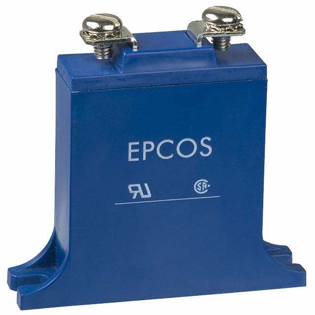
| 描述 | VARISTOR 387V 6KA DISC 14MM压敏电阻 THERMALLY PROTECTED VARISTOR 14MM |
| 产品分类 | |
| 品牌 | Littelfuse Inc |
| 产品手册 | |
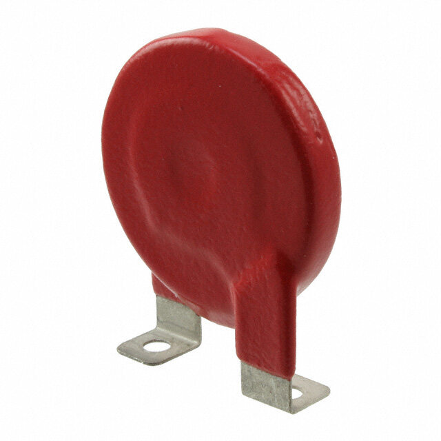
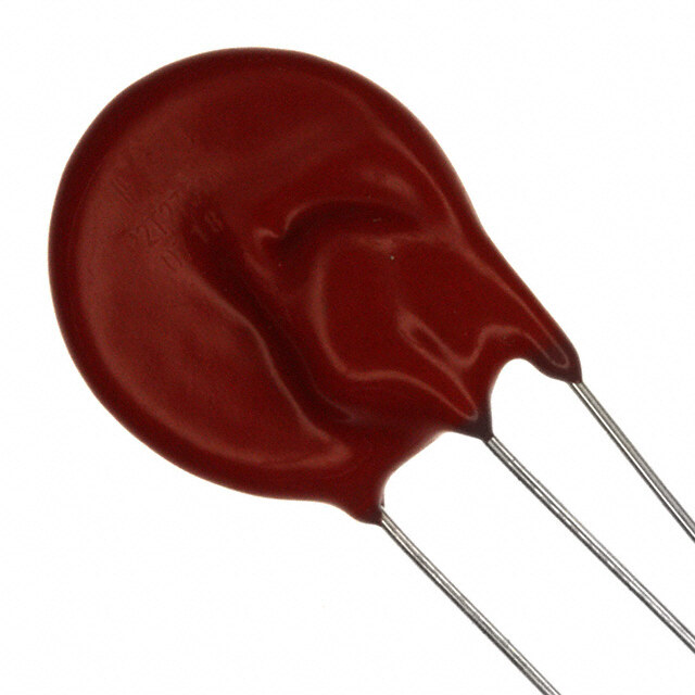
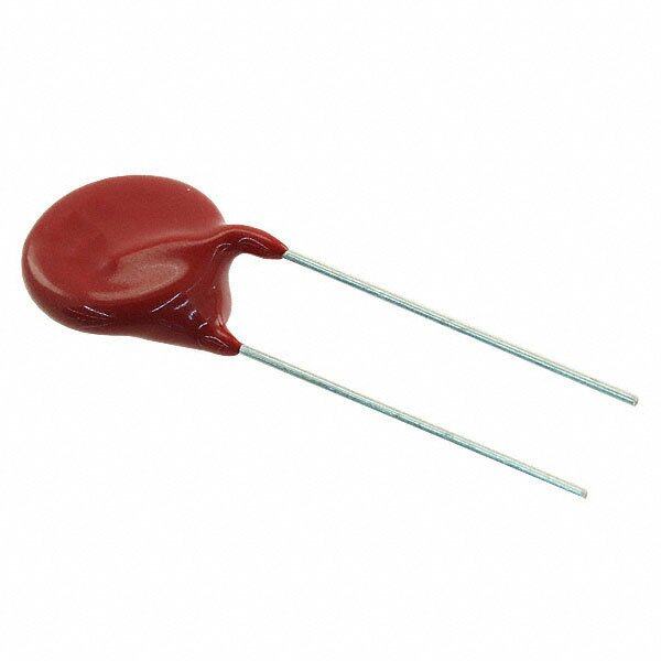
| 产品图片 |
|
| rohs | 符合RoHS无铅 / 符合限制有害物质指令(RoHS)规范要求 |
| 产品系列 | Littelfuse TMOV14RP275ETMOV® |
| 数据手册 | |
| 产品型号 | TMOV14RP275E |
| 产品 | MOV |
| 产品培训模块 | http://www.digikey.cn/PTM/IndividualPTM.page?site=cn&lang=zhs&ptm=25313http://www.digikey.cn/PTM/IndividualPTM.page?site=cn&lang=zhs&ptm=25936 |
| 产品种类 | 压敏电阻 |
| 其它名称 | TMOV14R275EP |
| 包装 | 散装 |
| 变阻器电压 | 387V |
| 商标 | Littelfuse |
| 外壳直径 | 14 mm |
| 安装 | Radial |
| 封装 | Bulk |
| 封装/外壳 | 圆盘 14mm |
| 尺寸 | 14 mm Dia. |
| 峰值浪涌电流 | 6 kA |
| 工作温度范围 | - 55 C to + 85 C |
| 工厂包装数量 | 500 |
| 最大AC电压 | 275VAC |
| 最大DC电压 | 350VDC |
| 标准包装 | 500 |
| 电压额定值AC | 275 V |
| 电容 | 450 pF |
| 电流-浪涌 | 6kA |
| 电路数 | 1 |
| 直径 | 14 mm |
| 端接类型 | Radial |
| 能量 | 110J |
| 钳位电压 | 710 V |


- 商务部:美国ITC正式对集成电路等产品启动337调查
- 曝三星4nm工艺存在良率问题 高通将骁龙8 Gen1或转产台积电
- 太阳诱电将投资9.5亿元在常州建新厂生产MLCC 预计2023年完工
- 英特尔发布欧洲新工厂建设计划 深化IDM 2.0 战略
- 台积电先进制程称霸业界 有大客户加持明年业绩稳了
- 达到5530亿美元!SIA预计今年全球半导体销售额将创下新高
- 英特尔拟将自动驾驶子公司Mobileye上市 估值或超500亿美元
- 三星加码芯片和SET,合并消费电子和移动部门,撤换高东真等 CEO
- 三星电子宣布重大人事变动 还合并消费电子和移动部门
- 海关总署:前11个月进口集成电路产品价值2.52万亿元 增长14.8%


PDF Datasheet 数据手册内容提取
Metal-Oxide Varistors (MOVs) Radial Lead Varistors > TMOV® and iTMOV® Varistor Series TMOV® and iTMOV® Varistor Series RoHS Description The Littelfuse TMOV® and iTMOV® thermally protected varistors represent a new development in integrated circuit protection. Both versions are comprised of radial leaded Metal Oxide Varistors (MOVs) with an integrated thermally activated element designed to open in the event of overheating due to the abnormal overvoltage, limited current, conditions outlined in UL1449. The TMOV® and iTMOV® varistor’s integrated thermal element, in conjunction with appropriate enclosure design, helps facilitate SPD module compliance to UL1449 for both cord connected and permanently connected applications. The TMOV® and iTMOV® varistors offer quick thermal response due to the close proximity of the integrated thermal element to the MOV body. The integrated Agency Approvals configuration also offers lower inductance than most discrete solutions resulting in improved clamping Agency Agency Approval Agency File Number performance to fast overvoltage transients. UL1449 E320116 The iTMOV® varistor differs from the TMOV® varistor by the inclusion of a third lead for the purpose of indicating that QC 42201-C001, the MOV has been disconnected from the circuit. This lead QC 42201-A001, IECQ-C BSI 15.0009 IEC 60950-1 (Annex Q) facilitates connection to monitoring circuitry. IEC 61051-1, Additionally TMOV® and iTMOV® varistors are wave IEC 61051-2, 40021525 solderable, thus simplifying end product assembly by IEC 60950-1 (Annex Q) reducing the the expense and rework associated with hand soldering operations. Additional Information Features • RoHS compliant and • -55°C to +85°C Lead–free available operating temp range • Designed to facilitate • Three-lead version Datasheet Resources Samples compliance to UL1449 available for indication iTMOV iTMOV iTMOV for SPD products purposes • High peak surge current rating up to 10kA • Wave solderable Datasheet Resources Samples • Standard lead form TMOV TMOV TMOV and spacing option Applications • SPD Products • GFCI (Ground Fault • AC Panel Protection Current Interupter) Modules • UPS (Uninterruptable • AC Line Power Supplies Power Supply) • White Goods • Surge Protected Strip Connectors • Plug-in SPD • AC Power Meters • Inverters • Relocatable AC • AC/DC Power Supplies Power Taps © 2017 Littelfuse, Inc. Specifications are subject to change without notice. Revised: 09/14/17
Metal-Oxide Varistors (MOVs) Radial Lead Varistors > TMOV® and iTMOV® Varistor Series Absolute Maximum Ratings • For ratings of individual members of a series, see Device Ratings and Specifications chart Continuous TMOV® and iTMOV® Varistor Series Units Steady State Applied Voltage: AC Voltage Range (V ) 115 to 750 V M(AC)RMS Transient: Peak Pulse Current (I ) - For 8x20µs Current Wave, single pulse 6,000 to 10,000 A TM Single-Pulse Energy Capability - For 2ms Current Wave 35 to 480 J Operating Ambient Temperature Range (T ) -55 to +85 °C A Storage Temperature Range (T ) -55 to +125 °C STG Temperature Coefficient (αV) of Clamping Voltage (V ) at Specified Test Current <0.01 %/°C C Hi-Pot Encapsulation (COATING Isolation Voltage Capability) 2,500 V Thermal Protection Isolation Voltage Capability (when operated) 600 V COATING Insulation Resistance 1,000 MΩ Indicator Lead Rating (Lead-3 - iTMOV® varistor only): Continuous RMS current 100 mA Surge Current, 8/20µs 10,000 A CAUTION: Stresses above those listed in “Absolute Maximum Ratings” may cause permanent damage to the device. This is a stress only rating and operation of the device at these or any other conditions above those indicated in the operational sections of this specification is not implied. Ratings & Specifications Maximum Rating (85°C) Specifications (25°C) TMOV® Varistor iTMOV® Varistor Continuous Transient Varistor Maximum Typical Lead–free And RoHS Lead–free and RoHS Voltage at Clamping Capaci- Compliant Models Compliant Models Disc AC DC Energy Peak Surge 1mA Test Voltage tance Diameter Volts Volts 2ms Current 8/20µs Current 8/20µs f = 1MHz I 1 × I 2 × V V Part Part V V W TM TM N(DC) N(DC) V I C Branding Branding M(AC)RMS M(DC) TM Pulse Pulse Min Max C PK Number Number (mm) (V) (V) (J) (A) (A) (V) (V) (A) (pF) TMOV14RP115E P4T115E TMOV14RP115M P4T115M 14 115 150 35 6000 4500 162 198 300 50 1100 TMOV20RP115E P2T115E TMOV20RP115M P2T115M 20 115 150 52 10000 6500 162 198 300 100 2400 TMOV14RP130E P4T130E TMOV14RP130M P4T130M 14 130 170 50 6000 4500 184.5 225.5 340 50 1000 TMOV20RP130E P2T130E TMOV20RP130M P2T130M 20 130 170 100 10000 6500 184.5 225.5 340 100 1900 TMOV14RP140E P4T140E TMOV14RP140M P4T140M 14 140 180 55 6000 4500 198 242 360 50 900 TMOV20RP140E P2T140E TMOV20RP140M P2T140M 20 140 180 110 10000 6500 198 242 360 100 1750 TMOV14RP150E P4T150E TMOV14RP150M P4T150M 14 150 200 60 6000 4500 216 264 395 50 800 TMOV20RP150E P2T150E TMOV20RP150M P2T150M 20 150 200 120 10000 6500 216 264 395 100 1600 TMOV14RP175E P4T175E TMOV14RP175M P4T175M 14 175 225 70 6000 4500 243 297 455 50 700 TMOV20RP175E P2T175E TMOV20RP175M P2T175M 20 175 225 135 10000 6500 243 297 455 100 1400 TMOV14RP200E P4T200E TMOV14RP200M P4T200M 14 200 260 75 6000 4500 283 345 530 50 630 TMOV20RP200E P2T200E TMOV20RP200M P2T200M 20 200 260 154 10000 6500 283 345 530 100 1250 TMOV14RP230E P4T230E TMOV14RP230M P4T230M 14 230 300 80 6000 4500 324 396 595 50 550 TMOV20RP230E P2T230E TMOV20RP230M P2T230M 20 230 300 160 10000 6500 324 396 595 100 1100 TMOV14RP250E P4T250E TMOV14RP250M P4T250M 14 250 320 100 6000 4500 351 429 650 50 500 TMOV20RP250E P2T250E TMOV20RP250M P2T250M 20 250 320 170 10000 6500 351 429 650 100 1000 TMOV14RP275E P4T275E TMOV14RP275M P4T275M 14 275 350 110 6000 4500 387 473 710 50 450 TMOV20RP275E P2T275E TMOV20RP275M P2T275M 20 275 350 190 10000 6500 387 473 710 100 900 TMOV14RP300E P4T300E TMOV14RP300M P4T300M 14 300 385 125 6000 4500 423 517 775 50 400 TMOV20RP300E P2T300E TMOV20RP300M P2T300M 20 300 385 250 10000 6500 423 517 775 100 800 TMOV14RP320E P4T320E TMOV14RP320M P4T320M 14 320 420 136 6000 4500 459 561 840 50 380 TMOV20RP320E P2T320E TMOV20RP320M P2T320M 20 320 420 270 10000 6500 459 561 840 100 750 TMOV14RP385E P4T385E TMOV14RP385M P4T385M 14 385 505 150 6000 4500 558 682 1025 50 360 TMOV20RP385E P2T385E TMOV20RP385M P2T385M 20 385 505 300 10000 6500 558 682 1025 100 700 TMOV14RP420E P4T420E TMOV14RP420M P4T420M 14 420 560 160 6000 4500 612 748 1120 50 300 TMOV20RP420E P2T420E TMOV20RP420M P2T420M 20 420 560 320 10000 6500 612 748 1120 100 600 TMOV14RP460E P4T460E TMOV14RP460M P4T460M 14 460 610 180 6000 4500 675 825 1240 50 220 TMOV20RP460E P2T460E TMOV20RP460M P2T460M 20 460 610 360 10000 6500 675 825 1240 100 200 TMOV14RP510E P4T510E TMOV14RP510M P4T510M 14 510 670 185 6000 4500 738 902 1355 50 200 TMOV20RP510E P2T510E TMOV20RP510M P2T510M 20 510 670 325 10000 6500 738 902 1355 100 350 TMOV14RP550E P4T550E TMOV14RP550M P4T550M 14 550 715 190 6000 4500 819 1001 1500 50 180 TMOV20RP550E P2T550E TMOV20RP550M P2T550M 20 550 715 360 10000 6500 819 1001 1500 100 300 © 2017 Littelfuse, Inc. Specifications are subject to change without notice. Revised: 09/14/17
Metal-Oxide Varistors (MOVs) Radial Lead Varistors > TMOV® and iTMOV® Varistor Series Ratings & Specifications Maximum Rating (85°C) Specifications (25°C) TMOV® Varistor iTMOV® Varistor Continuous Transient Typical Varistor Voltage Maximum Lead–free And RoHS Lead–free and RoHS Capaci- Compliant Models Compliant Models Disc AC DC Energy Peak Surge at 1mA Test Clamping tance Diameter Volts Volts 2ms Current 8/20µs Current Voltage 8/20µs f = 1MHz I 1 × I 2 × V Part Part V V W TM TM N(DC) V Max V I C Branding Branding M(AC)RMS M(DC) TM Pulse Pulse Min N(DC) C PK Number Number (mm) (V) (V) (J) (A) (A) (V) (V) (A) (pF) TMOV14RP575E P4T575E TMOV14RP575M P4T575M 14 575 730 195 6000 4500 857 1047 1568 50 170 TMOV20RP575E P2T575E TMOV20RP575M P2T575M 20 575 730 375 10000 6500 857 1047 1568 100 275 TMOV14RP625E P4T625E TMOV14RP625M P4T625M 14 625 825 200 6000 4500 900 1100 1650 50 160 TMOV20RP625E P2T625E TMOV20RP625M P2T625M 20 625 825 400 10000 6500 900 1100 1650 100 250 TMOV14RP750E P4T750E TMOV14RP750M P4T750M 14 750 970 210 6000 4500 1080 1320 1980 50 140 TMOV20RP750E P2T750E TMOV20RP750M P2T750M 20 750 970 480 10000 6500 1080 1320 1980 100 175 Thermal Characteristics Current, Energy, Power Derating Curve 10 100 Typical E U 5A VAL 80 2.5A D 0.5A E 0.125A AT 60 1 R F O NT 40 E C R E P 20 0.1 10 100 1000 10000 0 -55 50 60 70 80 90 100 110 120 130 Time(s) AMBIENT TEMPERATURE (oC) Figure 1 Figure 2 * Figure 4: Typical time to open circuit under UL1449 Note : Th e A TbMnOorVm®a al nOdv ieTrMvoOltaVg®e v Lairmisittoerds Caurerr einntte Tnedset d, in conjunction For applications exceeding 85°C ambient temperature, the peak with appropriate enclosure design, to help facilitate SPD module surge current and energy ratings must be reduced as shown compliance to UL 1449, 3rd Edition Section 39.4 (abnormal above. overvoltage limited current requirements). Under these extreme abnormal overvoltage conditions, some units will exhibit substantial heating, arcing and venting prior to opening. Modules should be designed to contain this possibility. Application testing is strongly recommended. Maximum Clamping Voltage for 14mm Parts Maximum Clamping Voltage for 20mm Parts 10000 Maximum Clamping Voltage 10000 750V Maximum Clamping Voltage Clamping Voltage (V) 1000 Maximum Leakage Current 255346433571586222075005050005VVVVVVVVVV Clamping Voltage (V) 1000 Maximum Leakage Current 523534643557810622270550005005VVVVVVVVVV 750V 250V 250V 230V 230V 200V 200V 175V 175V 100 111115345000VVVV 100 111151340500VVVV 0.000001 0.000010.0001 0.001 0.01 0.1 1 10 100 1000 10000 0.0000010.000010.0001 0.001 0.01 0.1 1 10 100 1000 10000 Peak Current (A) Peak Current (A) Figure 7: V-I Characteristic Curves for 20mm Types Figure 3 Figure 4 Figure 6: V-I Characteristic Curves for 14mm Types © 2017 Littelfuse, Inc. Specifications are subject to change without notice. Revised: 09/14/17
Metal-Oxide Varistors (MOVs) Radial Lead Varistors > TMOV® and iTMOV® Varistor Series Repetitive Surge Capability for 14mm Parts Repetitive Surge Capability for 20mm Parts 10000 1 2 15 10000 1 2 15 102 102 103 103 104 104 1000 105 1000 105 A) 106 A) 106 Peak Current ( 100 Peak Current ( 100 10 10 1 1 10 100 1000 10000 10 100 1000 10000 Figure 5 Impulse Duration (µs) Figure 6 Impulse Duration (μs) NOTE: AveraFgieg puorwee r8 d: isPsuiplastieon R oaf ttrianngsi eCntus rsvheousl df onort 1ex4cmeemd 0 .t6yWpes NOTE: Average power dissipation of transients should not exceed 1.0W Figure 9: Pulse Rating Curves for 20mm types Wave Solder Profile Because the TMOV® and iTMOV® varistors contain a thermal protection device, care must be taken when soldering the devices into place. Two soldering methods are possible. Firstly, hand soldering: It is recommended to heat-sink the leads of the device. Secondly, wave solder- ing: It is critically important that all preheat stage and the solder bath temperatures are rigidly controlled. Non Lead–free Profile Lead–free Profile 300 300 Maximum Wave 260C Maximum Wave 240C 250 250 C) C) E (º 200 E (º 200 R R U U T T A 150 A 150 R R E E P P M 100 M 100 E E T T 50 50 0 0 0 0.5 1 1.5 2 2.5 3 3.5 4 0 0.5 1 1.5 2 2.5 3 3.5 4 Figure 7 TIME(MINUTES) Figure 8 TIME(MINUTES) Physical Specifications Environmental Specifications Operating/Storage -55°C to +85°C Lead Material Copper clad steel wire Temperature +85°C, 85% RH , 1000 hours Humidity Aging Soldering Solderability per MIL–STD–202, +/-10% typical voltage change Characteristics Method 208 +85°C to -55°C 5 times Thermal Shock +/-10% typical voltage change Cured, flame retardant epoxy polymer Insulating Material meets UL94 V–0 requirements Solvent Resistance MIL–STD–202, Method 215 Marked with LF, voltage, UL/CSA logos, Device Labeling and date code Moisture Sensitivity Level 1, J-STD-020 © 2017 Littelfuse, Inc. Specifications are subject to change without notice. Revised: 09/14/17
Metal-Oxide Varistors (MOVs) Radial Lead Varistors > TMOV® and iTMOV® Varistor Series Lead Configurations TMOV® Varistor iTMOV® Varistor 2 Thermal Thermal Fuse Fuse Element Element 3 Monitor Lead Line MOV Line Fuse 3 MOV uit Circ 1 2 1 ed ect Note: MOVs are non-polarized passive elements iTMOV VariMstoornitor LeadLED Prot o T R iTMOV® Varistor Application Examples Neutral The application examples below show how the indicator lead on the iTMOV® varistor can be used to indicate that the Figure 1. Application example 1 thermal element has been opened. This signifies that the circuit is no longer protected from transients by the MOV. Line Application Example 1 Application Example 3 Line Fuse uit Circ In this case, the LED is normally on, and is off when the This circuit illustrates the use of the monitoring lead od f e thermal element opens. the iTMOV® viaTMrisOVto Vra rtisoto rensure that Requipment is onlyotect operated when overvoltage protection present. In noPrrmal AC OPTOCOUPLER o Line operation the load switch relay solenoid is powered vTia the TO STATUS Line Fuse uit indicator lead of the iTMOV® varistor. In the eALvINGeNHUTn/NAtCL IAAoRTMOfR the Circ thermal eNleeumtrael nt being activated, the relay will de-activate, iTMOV Varistor LED otected cilluutmtiniFngiga uptreeo .2w. Aeprp lticoat itohn eex pamropltee 2cted circuit and the fault LED will Pr o Line T Line R ApplicFaigLLtuiinnireeoeN 1Fen.uu iA stTrEepMaplxOliaVca mVtiaornpis eltoexra m2ple 1 LED To Protected Circuit Line FuseiTMOV Varistor Fault LED L(looassd oSfw p" inrLtoceohotae ndRc lPteaioolmawnyp)ered" otected Circuit Line Fuse R uit (Normallyoff) To Pr This circuNite uutrtaillizes an optocoupler to provide Circ Neutral R galvanic isolations between the iTMOV® varistor d e and thFiegu irne d1. iAcpaptliicniaTgtMio nOo Verx Vaaamlraipsrltemo r1 circuitry. R otect Figure 3. Application example 3 Pr AC OPTOCOUPLER o Please note: Indicator circuits are provided as a Line T TO STATUS guideline only. Verification of actual indicator circuitry LineN Feuustreal ALINGNHUT/NACLIAARTd CircuitMOR ivsa ltuhees r esespleocntesidb imlituy sotf b teh ea pepnrdo pursiaetre. Cfoorm thpeo nsepnetc ific Figure 2. iATpMpOliVca Vtiaornis etoxrample 2 R otecte AC line voltage service and application. Pr AC OPTOCOUPLER o T Line TO STATUS ANNUNCIATOR NLeinuetr aFluse L(looassd oSfw LpIiGrtocHhteT Rc/AteiolLanAy)RM Figure 2. Application example 2 " nLeooand lPaomwpered" Circuit iTMOV Varistor ed ect Line F(Naourltm LaElDlyoff) Prot o Line Fuse L(looassd oSfw pirtochte RRcteiolany) T FigureN 3e.u Atrpapllication example 3 " nLeooand lPaomwpered" Circuit iTMOV Varistor ed ect © 2017 Littelfuse, Inc. F(Naourltm LaElDlyoff) Prot Specifications are subject to change without notice. o Revised: 09/14/17 T R Neutral Figure 3. Application example 3
Metal-Oxide Varistors (MOVs) Radial Lead Varistors > TMOV® and iTMOV® Varistor Series Device Dimensions Straight Lead Forms Curved Lead Forms TMOV® Varistor iTMOV® Varistor TMOV® Varistor iTMOV® Varistor (outer crimp) (inner crimp) Dia D Dia D Dia D Dia D A A Monitor Monitor Lead Lead L3 L3 Seating L L Plane Dia c Dia c Dia b Dia b e3 Dia b Dia b e3 E E E E e e1 e e1 e e1 e e1 e2 e2 TMOV® Varistor iTMOV® Varistor V Dimension VolRtaMgSe 14mm Size 20mm Size 14mm Size 20mm Size Model Min. Max. Min. Max. Min. Max. Min. Max. mm (in) mm (in) mm (in) mm (in) mm (in) mm (in) mm (in) mm (in) A ALL 17.0 (0.669) 22.0 (0.866) 23.0 (0.906) 28.0 (1.10) 17.0 (0.669) 22.0 (0.866) 23.0 (0.906) 28.0 (1.10) Straight Lead A ALL -- 22.5 (0.886) -- 31.0 (1.221) -- 22.5 (0.886) -- 31.0 (1.221) Crimped Lead Dia D ALL 13.5 (0.531) 17.0 (0.669) 19.0 (0.748) 23.0 (0.906) 13.5 (0.531) 17.0 (0.669) 19.0 (0.748) 23.0 (0.906) e ALL 6.5 (0.256) 8.5 (0.335) 6.5 (0.256) 8.5 (0.335) 6.5 (0.256) 8.5 (0.335) 6.5 (0.256) 8.5 (0.335) 115-175 1.5 (0.059) 4.0 (0.157) 1.5 (0.059) 4.0 (0.157) 1.5 (0.059) 4.0 (0.157) 1.5 (0.059) 4.0 (0.157) e1 200-275 2.0 (0.079) 4.5 (0.177) 2.0 (0.079) 4.5 (0.177) 2.0 (0.079) 4.5 (0.177) 2.0 (0.079) 4.5 (0.177) Bulk Pack 300-420 3.0 (0.118) 5.5 (0.217) 3.0 (0.118) 5.5 (0.217) 3.0 (0.118) 5.5 (0.217) 3.0 (0.118) 5.5 (0.217) 460-750 0 2.0 (0.079) 0 2.0 (0.079) 0 2.0 (0.079) 0 2.0 (0.079) e1 115-420 0 2.0 (0.079) 0 2.0 (0.079) 0 2.0 (0.079) 0 2.0 (0.079) Tape & Reel and In-Line Lead 460-550* 0 2.0 (0.079) 0 2.0 (0.079) 0 2.0 (0.079) 0 2.0 (0.079) e2 ALL n/a n/a n/a n/a 4.0 (0.157) 6.0 (0.236) 4.0 (0.157) 6.0 (0.236) e3 ALL n/a n/a n/a n/a 0 2.0 (0.079) 0 2.0 (0.079) 115-175 -- 9.0 (0.354) -- 9.0 (0.354) -- 9.0 (0.354) -- 9.0 (0.354) 200-275 -- 9.5 (0.374) -- 9.5 (0.374) -- 9.5 (0.374) -- 9.5 (0.374) E 300-460 -- 11.0 (0.433) -- 11.0 (0.433) -- 11.0 (0.433) -- 11.0 (0.433) 510-575 -- 12.0 (0.472) -- 12.0 (0.472) -- 12.0 (0.472) -- 12.0 (0.472) 625-750 -- 13.0 (0.512) -- 13.0 (0.512) -- 13.0 (0.512) -- 13.0 (0.512) L ALL 25.4 (1.00) -- 25.4 (1.00) -- 25.4 (1.00) -- 25.4 (1.00) -- L3 ALL n/a n/a n/a n/a 6.0 (0.236) -- 6.0 (0.236) -- 115-420 0.76 (0.030) 0.86 (0.034) 0.76 (0.030) 0.86 (0.034) 0.76 (0.030) 0.86 (0.034) 0.76 (0.030) 0.86 (0.034) Dia b 460-750 0.76 (0.030) 0.86 (0.034) 0.95 (0.037) 1.05 (0.041) 0.76 (0.030) 0.86 (0.034) 0.95 (0.037) 1.05 (0.041) Dia c ALL n/a n/a n/a n/a 0.76 (0.030) 0.86 (0.034) 0.76 (0.030) 0.86 (0.034) Outside Lead Only NOTES: * Tape and Reel packaging option is available only for devices up to 420Vrms. © 2017 Littelfuse, Inc. Specifications are subject to change without notice. Revised: 09/14/17
Metal-Oxide Varistors (MOVs) Radial Lead Varistors > TMOV® and iTMOV® Varistor Series Tape and Reel Specification iTMOV® VARISTOR WITH INNER CRIMP TMOV® VARISTOR WITH OUTER CRIMP P E P E P2 ∆P ∆P P2 ∆P ∆P ∆H ∆H ∆H ∆H B1 B1 H1 S PELAATNINEG C H1 S PELAATNINEG C W0 W2 W1 W0 W2 W1 H0 Øb H0 Øb W W ØD0 ØD0 P1P0 F t P1P0 F t iTMOV® VARISTOR WITH STRAIGHT LEADS TMOV® VARISTOR WITH STRAIGHT LEADS P E P E P2 ∆P ∆P P2 ∆P ∆P ∆H ∆H ∆H ∆H H1 H1 H W0 W2 W1 H W0 W2 W1 Øb Øb L L W W ØD0 ØD0 P1P0 F t P1P0 F t CRIMPED LEADS STRAIGHT LEADS DESCRIPTION MODEL SIZE MODEL SIZE 14mm 20mm 14mm 20mm B Component Top to Seating Plane 22.5 Max 31 Max 22.0 Max 28.0 Max 1 P Pitch of Component 25.4 +/- 1.0 25.4 +/- 1.0 25.4 ±1.0 25.4 ±1.0 P Feed Hole Pitch 12.7 +/- 0.2 12.7 +/- 0.2 12.7 ±0.2 12.7 ±0.2 0 P Feed Hole Center to Pitch 8.95 +/- 0.7 8.95 +/- 0.7 8.95 ±0.7 8.95 ±0.7 1 P Hole Center to Component Center 12.7 +/- 0.7 12.7 +/- 0.7 12.7 ±0.7 12.7 ±0.7 2 F Lead to Lead Distance 7.5 +/- 0.8 7.5 +/- 0.8 7.5 ±0.8 7.5 ±0.8 Δh Component Alignment 2.0 Max 2.0 Max 2.0 Max 2.0 Max W Tape Width 18.0 +1.0/-0.5 18.0 +1.0/-0.5 18.0 +1.0/-0.5 18.0 +1.0/-0.5 W Hold Down Tape Width 12.0 +/- 0.3 12.0 +/- 0.3 12.0 ±0.3 12.0 ±0.3 0 W Hole Position 9.0 +0.75/-0.50 9.0 +0.75/-0.50 9.0 +0.75/-0.5 9.0 +0.75/-0.5 1 W Hold Down Tape Position 0.5 Max 0.5 Max 0.5 Max 0.5 Max 2 NOTES: Height from Tape Centre to Component • Dimensions in mm H -- -- 18.0 +2.0/-0 18.0 +2.0/-0 Base (non-crimped parts) • Reel capacity varies with voltage. H Seating Plane Height (crimped parts only) 16.0 +/- 0.5 16.0 +/- 0.5 -- -- • Leads are crimped and in-line. 0 This excludes the monitor lead H Component Height 40.0 Max 46.5 Max 40.0 Max 46.5 Max on iTMOV® varistor which are not 1 crimped and not in-line. C Crimp Length (crimped parts only) 2.6 typ 2.6 typ -- -- • To order tape and reel option please add suffix 'L2T7' to end of D Feed Hole Diameter 4.0 +/- 0.2 4.0 +/- 0.2 4.0 ±0.2 4.0 ±0.2 standard part number. 0 t Total Tape Thickness 0.7 +/- 0.2 0.7 +/- 0.2 0.7 ±0.2 0.7 ±0.2 • Tape and reel option is available for rated voltages up to L Length of Clipped Lead 11.0 Max 11.0 Max 11.0 Max 11.0 Max 420V. Contact factory regarding availability of higher voltages. Δp Component Alignment 3 Max. 1.00mm 3 Max 3 deg Max, 3 deg Max, • Contact Littelfuse for additional 1.0mm Max 1.0mm Max details. © 2017 Littelfuse, Inc. Specifications are subject to change without notice. Revised: 09/14/17
Metal-Oxide Varistors (MOVs) Radial Lead Varistors > TMOV® and iTMOV® Varistor Series Part Numbering System Base Part Codes Option Codes1 (See ratings & specifications tables and notes below) (See below) TMOV 20 R P 150 E XXXXX DEVICE FAMILY NON-STANDARD LEAD FORM, PACKAGING Littelfuse Thermally Protected MOV and LEAD SPACING OPTIONS1: DISC DIAMETER (mm) L2B7: Lead Form: Crimped and In-Line2 Leads 14 or 20mm Packaging: Bulk Pack CERAMIC SHAPE Lead Spacing3: 7.5mm R: Round LEAD-FREE/RoHS L2T7: Lead Form: Crimped and In-Line2 Leads COMPLIANT INDICATOR Packaging: Tape and Reel4 Lead Spacing3: 7.5mm V M(AC)RMS 115V to 750V L3T7: Lead Form: Straight Leads and In-Line2 Leads SERIES DESIGNATOR Packing: Tape and Reel E: TMOV (2-Leaded, without indicator lead) Lead Spacing: 7.5mm M: iTMOV (3-Leaded, with indicator lead option) Option Codes: X2855: Nickel Barrier coated wire option -- All standard parts use tinned copper clad steel wire. Nickel Barrier coated wire is available as an option, consisting of Copper wire with a flashing of Nickel NOTES: followed by a top coating of Tin. To order append standard model BASE PART number with "X2855." Example: 1 Use Base Part Code only to receive standard product: Standard Model Order As Lead Form: Straight Leads. Devices greater than 420Vrms are TMOV20RP115E TMOV20RP115EX2855 provided In-Line2. LPeacakda Sgpinagc:i nBgu:l k7. 5Pmacmk +/-1.0mm Other non-standard options may be available - please contact Littelfuse. 2 “In-Line” refers to straight row of leads at the tip where product is to contact the circuit board. Refer to “e1” in Device Dimensions section. 3 Lead Spacing refers to span between leads as “e” dimension in Device Dimensions section. 4 Due to device bulk, tape and reel packaging option is available only for devices up to 420Vrms. Pack Quantities Pack Quantities Rated Bulk Pack Tape and Reel Voltage Model Size Model Size 14mm 20mm 14mm 20mm 115-250 600 400 500 400 275-550 500 300 400 300 575-750 400 200 n/a n/a NOTE: Tape and Reel available up to 420V only - please contact factory regarding availability of higher voltage parts. Disclaimer Notice - Information furnished is believed to be accurate and reliable. However, users should independently evaluate the suitability of and test each product selected for their own applications. Littelfuse products are not designed for, and may not be used in, all applications. Read complete Disclaimer Notice at www.littelfuse.com/disclaimer-electronics. © 2017 Littelfuse, Inc. Specifications are subject to change without notice. Revised: 09/14/17