 Datasheet下载
- 型号: TLC3704IN
- 制造商: Texas Instruments
- 库位|库存: xxxx|xxxx
- 要求:
| 数量阶梯 | 香港交货 | 国内含税 |
| +xxxx | $xxxx | ¥xxxx |
查看当月历史价格
查看今年历史价格
TLC3704IN产品简介:
ICGOO电子元器件商城为您提供TLC3704IN由Texas Instruments设计生产,在icgoo商城现货销售,并且可以通过原厂、代理商等渠道进行代购。 TLC3704IN价格参考¥4.70-¥11.65。Texas InstrumentsTLC3704IN封装/规格:线性 - 比较器, 通用 比较器 CMOS,推挽式,TTL 14-PDIP。您可以下载TLC3704IN参考资料、Datasheet数据手册功能说明书,资料中有TLC3704IN 详细功能的应用电路图电压和使用方法及教程。
TLC3704IN 是 Texas Instruments(德州仪器)生产的一款四路电压比较器,属于线性比较器类别。该器件广泛应用于需要将模拟信号与参考电平进行比较的场合,常用于电平检测、电压监控、窗口检测、信号调理和控制系统中。

典型应用场景包括:

1. 电源监控与过压保护:用于检测电源电压是否超出设定范围,触发保护电路,防止设备损坏。
2. 电池管理系统:监测电池电压,判断电池是否过充或过放,实现智能管理。
3. 温度控制系统:配合温度传感器使用,当温度超过设定阈值时,控制风扇或加热装置启停。
4. 工业自动化控制:在PLC或传感器系统中用于信号比较与开关控制。
5. 音频与通信设备:用于信号检测、门限判断或波形整形。
6. 窗口比较器设计:通过组合多个比较器,判断输入信号是否在设定的电压窗口内。

该器件具有低功耗、宽电源电压范围(2.7V至16V)以及输出兼容TTL/CMOS等优点,适用于多种工业和消费类电子产品中。
| 参数 | 数值 |
| 产品目录 | 集成电路 (IC)半导体 |
| CMRR,PSRR(典型值) | 84dB CMRR |
| 描述 | IC VOLT COMPARATOR QUAD 14-DIP模拟比较器 Quad V |
| 产品分类 | |
| 品牌 | Texas Instruments |
| 产品手册 | |
| 产品图片 |
|
| rohs | 符合RoHS无铅 / 符合限制有害物质指令(RoHS)规范要求 |
| 产品系列 | 校验器 IC,Texas Instruments TLC3704INLinCMOS™ |
| 数据手册 | |
| 产品型号 | TLC3704IN |
| PCN设计/规格 | |
| 产品 | Analog Comparators |
| 产品目录页面 | |
| 产品种类 | 模拟比较器 |
| 传播延迟(最大值) | 4.5µs |
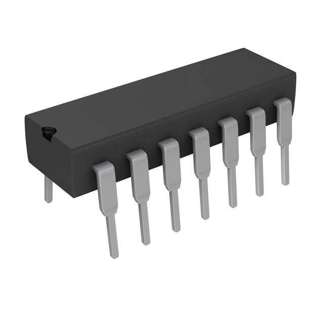
| 供应商器件封装 | 14-PDIP |
| 偏转电压—最大值 | 5 mV |
| 元件数 | 4 |
| 其它名称 | 296-10306-5 |
| 包装 | 管件 |
| 单位重量 | 1 g |
| 响应时间 | 1.1 us |
| 商标 | Texas Instruments |
| 安装类型 | 通孔 |
| 安装风格 | Through Hole |
| 封装 | Tube |
| 封装/外壳 | 14-DIP(0.300",7.62mm) |
| 封装/箱体 | PDIP-14 |
| 工作温度 | -40°C ~ 85°C |
| 工厂包装数量 | 25 |
| 最大功率耗散 | 1150 mW |
| 最大工作温度 | + 85 C |
| 最小工作温度 | - 40 C |
| 标准包装 | 25 |
| 比较器类型 | General Purpose |
| 滞后 | - |
| 电压-电源,单/双 (±) | 3 V ~ 16 V |
| 电压-输入失调(最大值) | 5mV @ 10V |
| 电流-输入偏置(最大值) | 5pA @ 5V |
| 电流-输出(典型值) | 20mA |
| 电流-静态(最大值) | 125µA |
| 电源电压-最大 | 16 V |
| 电源电压-最小 | 3 V |
| 电源电流 | 20 uA |
| 电源电流—最大值 | 20 uA |
| 类型 | 通用 |
| 系列 | TLC3704 |
| 输入偏压电流—最大 | 5 pA |
| 输出电流—典型值 | 4 mA |
| 输出类型 | CMOS,推挽式,TTL |
| 通道数量 | 4 Channel |


- 商务部:美国ITC正式对集成电路等产品启动337调查
- 曝三星4nm工艺存在良率问题 高通将骁龙8 Gen1或转产台积电
- 太阳诱电将投资9.5亿元在常州建新厂生产MLCC 预计2023年完工
- 英特尔发布欧洲新工厂建设计划 深化IDM 2.0 战略
- 台积电先进制程称霸业界 有大客户加持明年业绩稳了
- 达到5530亿美元!SIA预计今年全球半导体销售额将创下新高
- 英特尔拟将自动驾驶子公司Mobileye上市 估值或超500亿美元
- 三星加码芯片和SET,合并消费电子和移动部门,撤换高东真等 CEO
- 三星电子宣布重大人事变动 还合并消费电子和移动部门
- 海关总署:前11个月进口集成电路产品价值2.52万亿元 增长14.8%


PDF Datasheet 数据手册内容提取
TLC3704, TLC3704M QUAD MICROPOWER LinCMOS VOLTAGE COMPARATORS SLCS117C − NOVEMBER 1986 − REVISED NOVEMBER 2009 (cid:1) Push-Pull CMOS Output Drives Capacitive D, J, OR N PACKAGE Loads Without Pullup Resistor, (TOP VIEW) I = ± 8 mA O (cid:1) Very Low Power...200 µW Typ at 5 V 1OUT 1 14 3OUT 2OUT 2 13 4OUT (cid:1) Fast Response Time...tPLH = 2.7 µs Typ VDD 3 12 GND With 5-mV Overdrive 2IN− 4 11 4IN+ (cid:1) Single Supply Operation...3 V to 16 V 2IN+ 5 10 4IN− TLC3704M...4 V to 16 V 1IN− 6 9 3IN+ (cid:1) On-Chip ESD Protection 1IN+ 7 8 3IN− description PW PACKAGE The TLC3704 consists of four independent (TOP VIEW) micropower voltage comparators designed to 1OUT 1 14 3OUT operate from a single supply and be compatible 2OUT 2 13 4OUT with modern HCMOS logic systems. They are functionally similar to the LM339 but use 1/20th VDD 3 12 GND 2IN− 4 11 4IN+ the power for similar response times. The 2IN+ 5 10 4IN− push-pull CMOS output stage drives capacitive 1IN− 6 9 3IN+ loads directly without a power-consuming pullup 1IN+ 7 8 3IN− resistor to achieve the stated response time. Eliminating the pullup resistor not only reduces power dissipation, but also saves board space FK PACKAGE (TOP VIEW) and component cost. The output stage is also fully compatible with TTL requirements. UT UT UT UT O O CO O Texas Instruments LinCMOS process offers 2 1 N3 4 superior analog performance to standard CMOS 3 2 1 20 19 processes. Along with the standard CMOS VDD 4 18 GND advantages of low power without sacrificing NC 5 17 NC speed, high input impedance, and low bias 2IN− 6 16 4IN+ currents, the LinCMOS process offers extremely NC 7 15 NC stable input offset voltages with large differential 2IN+ 8 14 4IN− 9 10 11 12 13 input voltages. This characteristic makes it possible to build reliable CMOS comparators. − + C −+ N N N NN The TLC3704C is characterized for operation 1I 1I 3I3I over the commercial temperature range of 0°C to NC − No internal connection 70°C. The TLC3704I is characterized for operation over the extended industrial tempera- ture range of − 40°C to 85°C. The TLC3704M is symbol (each comparator) characterized for operation over the full military temperature range of − 55°C to 125°C. The IN+ TLC3704Q is characterized for operation from − OUT 40°C to 125°C. IN− Please be aware that an important notice concerning availability, standard warranty, and use in critical applications of TexasInstruments semiconductor products and disclaimers thereto appears at the end of this data sheet. LinCMOS is a trademark of Texas Instruments Incorporated. PRODUCTION DATA information is current as of publication date. Copyright 2009, Texas Instruments Incorporated Products conform to specifications per the terms of Texas Instruments standard warranty. Production processing does not necessarily include testing of all parameters. POST OFFICE BOX 655303 • DALLAS, TEXAS 75265 1
TLC3704, TLC3704M QUAD MICROPOWER LinCMOS VOLTAGE COMPARATORS SLCS117C − NOVEMBER 1986 − REVISED NOVEMBER 2009 AVAILABLE OPTIONS PACKAGE TA VVatIO 2mm5°aaCxx SMALL OUTLINE CERAMIC CERAMIC DIP PLASTIC DIP TSSOP (D) (FK) (J) (N) (PW) 0°C to 70°C 5 mV TLC3704CD — — TLC3704CN TLC3704CPW −40°C to 85°C 5 mV TLC3704ID — — TLC3704IN TLC3704IPW −55°C to 125°C 5 mV TLC3704MD TLC3704MFK TLC3704MJ — — −40°C to 125°C 5 mV — — TLC3704QJ — — The D and PW packages are available taped and reeled. Add R suffix to the device type (e.g., TLC3704CDR). functional block diagram (each comparator) VDD IN+ Differential Input OUT Circuits IN− GND absolute maximum ratings over operating free-air temperature range (unless otherwise noted)† Supply voltage range, V (see Note 1) . . . . . . . . . . . . . . . . . . . . . . . . . . . . . . . . . . . . . . . . . . . . . −0.3 V to 18 V DD Differential input voltage, V (see Note 2) . . . . . . . . . . . . . . . . . . . . . . . . . . . . . . . . . . . . . . . . . . . . . . . . . . . ±18 V ID Input voltage range, V . . . . . . . . . . . . . . . . . . . . . . . . . . . . . . . . . . . . . . . . . . . . . . . . . . . . . . . . . . . . . . . . −0.3 to V I DD Output voltage range, V . . . . . . . . . . . . . . . . . . . . . . . . . . . . . . . . . . . . . . . . . . . . . . . . . . . . . . . . . . . . . −0.3 to V O DD Input current, I . . . . . . . . . . . . . . . . . . . . . . . . . . . . . . . . . . . . . . . . . . . . . . . . . . . . . . . . . . . . . . . . . . . . . . . . . . ±5 mA I Output current, I (each output) . . . . . . . . . . . . . . . . . . . . . . . . . . . . . . . . . . . . . . . . . . . . . . . . . . . . . . . . . . . ±20 mA O Total supply current into V . . . . . . . . . . . . . . . . . . . . . . . . . . . . . . . . . . . . . . . . . . . . . . . . . . . . . . . . . . . . . . 40 mA DD Total current out of GND . . . . . . . . . . . . . . . . . . . . . . . . . . . . . . . . . . . . . . . . . . . . . . . . . . . . . . . . . . . . . . . . . . 60 mA Continuous total power dissipation . . . . . . . . . . . . . . . . . . . . . . . . . . . . . . . . . . . . . See Dissipation Rating Table Operating free-air temperature range, T :TLC3704C . . . . . . . . . . . . . . . . . . . . . . . . . . . . . . . . . . . . . . . 0 to 70°C A TLC3704I . . . . . . . . . . . . . . . . . . . . . . . . . . . . . . . . . . . −40°C to 85°C TLC3704M . . . . . . . . . . . . . . . . . . . . . . . . . . . . . . . . . −55°C to 125°C TLC3704Q . . . . . . . . . . . . . . . . . . . . . . . . . . . . . . . . . −40°C to 125°C Storage temperature range . . . . . . . . . . . . . . . . . . . . . . . . . . . . . . . . . . . . . . . . . . . . . . . . . . . . . . . . −65°C to 150°C Case temperature for 60 seconds: FK package . . . . . . . . . . . . . . . . . . . . . . . . . . . . . . . . . . . . . . . . . . . . . . 260°C Lead temperature 1,6 mm (1/16 inch) from case for 10 seconds: D or N package . . . . . . . . . . . . . . . . 260°C Lead temperature 1,6 mm (1/16 inch) from case for 60 seconds: J package . . . . . . . . . . . . . . . . . . . . . 300°C †Stresses beyond those listed under “absolute maximum ratings” may cause permanent damage to the device. These are stress ratings only, and functional operation of the device at these or any other conditions beyond those indicated under “recommended operating conditions” is not implied. Exposure to absolute-maximum-rated conditions for extended periods may affect device reliability. NOTES: 1. All voltage values, except differential voltages, are with respect to network ground. 2. Differential voltages are at IN+ with respect to IN−. 2 POST OFFICE BOX 655303 • DALLAS, TEXAS 75265
TLC3704, TLC3704M QUAD MICROPOWER LinCMOS VOLTAGE COMPARATORS SLCS117C − NOVEMBER 1986 − REVISED NOVEMBER 2009 DISSIPATION RATING TABLE PACKAGE TA ≤ 25°C DERATING FACTOR TA = 70°C TA = 85°C TA = 125°C POWER RATING ABOVE TA = 25°C POWER RATING POWER RATING POWER RATING D 950 mW 7.6 mW/°C 608 mW 494 mW N/A FK 1375 mW 11.0 mW/°C 880 mW 715 mW 275 mW J 1375 mW 11.0 mW/°C 880 mW 715 mW 275 mW N 1150 mW 9.2 mW/°C 736 mW 598 mW N/A PW 675 mW 5.4 mW/°C 432 mW 351 mW N/A recommended operating conditions TLC3704C UUNNIITT MIN NOM MAX Supply voltage, VDD 3 5 16 V Common-mode input voltage, VIC − 0.2 VDD − 1.5 V High-level output current, IOH − 20 mA Low-level output current, IOL 20 mA Operating free-air temperature, TA 0 70 °C electrical characteristics at specified operating free-air temperature, V = 5 V DD (unless otherwise noted) TLC3704C PPAARRAAMMEETTEERR TTEESSTT CCOONNDDIITTIIOONNSS†† TTA MIN TYP MAX UUNNIITT VDD = 5 V to 10 V, 25°C 1.2 5 VVIO IInnppuutt ooffffsseett vvoollttaaggee VIC = VICRmin, See Note 3 0°C to 70°C 6.5 mmVV 25°C 1 pA IIIO IInnppuutt ooffffsseett ccuurrrreenntt VVIC = 22.55 VV 70°C 0.3 nA 25°C 5 pA IIIB IInnppuutt bbiiaass ccuurrrreenntt VVIC = 22.55 VV 70°C 0.6 nA 0 to 25°C VDD − 1 VVICR CCoommmmoonn-mmooddee iinnppuutt vvoollttaaggee rraannggee 0 to VV 0°C to 70°C VDD − 1.5 25°C 84 CCMMRRRR CCoommmmoonn-mmooddee rreejjeeccttiioonn rraattiioo VVIICC = VVIICCRRmmiinn 70°C 84 ddBB 0°C 84 25°C 85 kkSSVVRR SSuuppppllyy-vvoollttaaggee rreejjeeccttiioonn rraattiioo VVDDDD = 55 VV ttoo 1100 VV 70°C 85 ddBB 0°C 85 25°C 4.5 4.7 VVOH HHiigghh-lleevveell oouuttppuutt vvoollttaaggee VVID = 11 VV, IIOH = −44 mmAA 70°C 4.3 VV 25°C 210 300 VVOL LLooww-lleevveell oouuttppuutt vvoollttaaggee VVID = −11 VV, IIOH = 44 mmAA 70°C 375 mmVV 25°C 35 80 IIDD SSuuppppllyy ccuurrrreenntt ((aallll ffoouurr ccoommppaarraattoorrss)) OOuuttppuuttss llooww, NNoo llooaadd 0°C to 70°C 100 µµAA †All characteristics are measured with zero common-mode voltage unless otherwise noted. NOTE 3: The offset voltage limits given are the maximum values required to drive the output up to 4.5 V or down to 0.3 V. POST OFFICE BOX 655303 • DALLAS, TEXAS 75265 3
TLC3704, TLC3704M QUAD MICROPOWER LinCMOS VOLTAGE COMPARATORS SLCS117C − NOVEMBER 1986 − REVISED NOVEMBER 2009 recommended operating conditions TLC3704I UUNNIITT MIN NOM MAX Supply voltage, VDD 3 5 16 V Common-mode input voltage, VIC − 0.2 VDD − 1.5 V High-level output current, IOH − 20 mA Low-level output current, IOL 20 mA Operating free-air temperature, TA − 40 85 °C electrical characteristics at specified operating free-air temperature, V = 5 V, V = 0 (unless DD IC otherwise noted) TLC3704I PPAARRAAMMEETTEERR TTEESSTT CCOONNDDIITTIIOONNSS TTA MIN TYP MAX UUNNIITT VDD = 5 V to 10 V, 25°C 1.2 5 VVIO IInnppuutt ooffffsseett vvoollttaaggee VIC = VICRmin, See Note 3 −40°C to 85°C 7 mmVV 25°C 1 pA IIIO IInnppuutt ooffffsseett ccuurrrreenntt VVIC = 22.55 VV 85°C 1 nA 25°C 5 pA IIIB IInnppuutt bbiiaass ccuurrrreenntt VVIC = 22.55 VV 85°C 2 nA 0 to 25°C VDD − 1 VVICR CCoommmmoonn-mmooddee iinnppuutt vvoollttaaggee rraannggee 0 to VV −40°C to 85°C VDD − 1.5 25°C 84 CCMMRRRR CCoommmmoonn-mmooddee rreejjeeccttiioonn rraattiioo VVIICC = VVIICCRRmmiinn 85°C 84 ddBB −40°C 83 25°C 85 kkSSVVRR SSuuppppllyy-vvoollttaaggee rreejjeeccttiioonn rraattiioo VVDDDD = 55 VV ttoo 1100 VV 85°C 85 ddBB −40°C 83 25°C 4.5 4.7 VVOH HHiigghh-lleevveell oouuttppuutt vvoollttaaggee VVID = 11 VV, IIOH = −44 mmAA 85°C 4.3 VV 25°C 210 300 VVOL LLooww-lleevveell oouuttppuutt vvoollttaaggee VVID = −11 VV, IIOH = 44 mmAA 85°C 400 mmVV 25°C 35 80 IIDD SSuuppppllyy ccuurrrreenntt ((aallll ffoouurr ccoommppaarraattoorrss)) OOuuttppuuttss llooww, NNoo llooaadd −40°C to 85°C 125 µµAA NOTE 3: The offset voltage limits given are the maximum values required to drive the output up to 4.5 V or down to 0.3 V. 4 POST OFFICE BOX 655303 • DALLAS, TEXAS 75265
TLC3704, TLC3704M QUAD MICROPOWER LinCMOS VOLTAGE COMPARATORS SLCS117C − NOVEMBER 1986 − REVISED NOVEMBER 2009 recommended operating conditions TLC3704M UUNNIITT MIN NOM MAX Supply voltage, VDD 4 5 16 V Common-mode input voltage, VIC 0 VDD − 1.5 V High-level output current, IOH − 20 mA Low-level output current, IOL 20 mA Operating free-air temperature, TA − 55 125 °C electrical characteristics at specified operating free-air temperature, V = 5 V, V = 0 (unless DD IC otherwise noted) TLC3704M PPAARRAAMMEETTEERR TTEESSTT CCOONNDDIITTIIOONNSS TTA MIN TYP MAX UUNNIITT VDD = 5 V to 10 V, 25°C 1.2 5 VVIO IInnppuutt ooffffsseett vvoollttaaggee VIC = VICRmin, See Note 3 −55°C to 125°C 10 mmVV 25°C 1 pA IIIO IInnppuutt ooffffsseett ccuurrrreenntt VVIC = 22.55 VV 125°C 15 nA 25°C 5 pA IIIB IInnppuutt bbiiaass ccuurrrreenntt VVIC = 22.55 VV 125°C 30 nA 0 to 25°C VDD − 1 VVICR CCoommmmoonn-mmooddee iinnppuutt vvoollttaaggee rraannggee 0 to VV −55°C to 125°C VDD − 1.5 25°C 84 CCMMRRRR CCoommmmoonn-mmooddee rreejjeeccttiioonn rraattiioo VVIICC = VVIICCRRmmiinn 125°C 83 ddBB −55°C 82 25°C 85 kkSSVVRR SSuuppppllyy-vvoollttaaggee rreejjeeccttiioonn rraattiioo VVDDDD = 55 VV ttoo 1100 VV 125°C 85 ddBB −55°C 82 25°C 4.5 4.7 VVOH HHiigghh-lleevveell oouuttppuutt vvoollttaaggee VVID = 11 VV, IIOH = −44 mmAA 125°C 4.2 VV 25°C 210 300 VVOL LLooww-lleevveell oouuttppuutt vvoollttaaggee VVID = −11 VV, IIOH = 44 mmAA 125°C 500 mmVV 25°C 35 80 IIDD SSuuppppllyy ccuurrrreenntt ((aallll ffoouurr ccoommppaarraattoorrss)) OOuuttppuuttss llooww, NNoo llooaadd −55°C to 125°C 175 µµAA NOTE 3: The offset voltage limits given are the maximum values required to drive the output up to 4.5 V or down to 0.3 V. POST OFFICE BOX 655303 • DALLAS, TEXAS 75265 5
TLC3704, TLC3704M QUAD MICROPOWER LinCMOS VOLTAGE COMPARATORS SLCS117C − NOVEMBER 1986 − REVISED NOVEMBER 2009 recommended operating conditions TLC3704Q UUNNIITT MIN NOM MAX Supply voltage, VDD 3 5 16 V Common-mode input voltage, VIC −0.2 VDD − 1.5 V High-level output current, IOH − 20 mA Low-level output current, IOL 20 mA Operating free-air temperature, TA − 40 125 °C electrical characteristics at specified operating free-air temperature, V = 5 V, V = 0 (unless DD IC otherwise noted) TLC3704Q PPAARRAAMMEETTEERR TTEESSTT CCOONNDDIITTIIOONNSS TTA MIN TYP MAX UUNNIITT VDD = 5 V to 10 V, 25°C 1.2 5 VVIO IInnppuutt ooffffsseett vvoollttaaggee VIC = VICRmin, See Note 3 −40°C to 125°C 7 mmVV 25°C 1 pA IIIO IInnppuutt ooffffsseett ccuurrrreenntt VVIC = 22.55 VV 125°C 15 nA 25°C 5 pA IIIB IInnppuutt bbiiaass ccuurrrreenntt VVIC = 22.55 VV 125°C 30 nA CCoommmmoonn-mmooddee iinnppuutt vvoollttaaggee 25°C 0 to VDD − 1 VVICR range −40°C to 125°C 0 to VDD − 1.5 VV 25°C 84 CCMMRRRR CCoommmmoonn-mmooddee rreejjeeccttiioonn rraattiioo VVIICC = VVIICCRRmmiinn 125°C 83 ddBB −40°C 83 25°C 85 kkSSVVRR SSuuppppllyy-vvoollttaaggee rreejjeeccttiioonn rraattiioo VVDDDD = 55 VV ttoo 1100 VV 125°C 85 ddBB −40°C 83 25°C 4.5 4.7 VVOH HHiigghh-lleevveell oouuttppuutt vvoollttaaggee VVID = 11 VV, IIOH = −44 mmAA 125°C 4.2 VV 25°C 210 300 VVOL LLooww-lleevveell oouuttppuutt vvoollttaaggee VVID = −11 VV, IIOH = 44 mmAA 125°C 500 mmVV SSuuppppllyy ccuurrrreenntt ((aallll ffoouurr 25°C 35 80 IIDD comparators) OOuuttppuuttss llooww, NNoo llooaadd −40°C to 125°C 175 µµAA NOTE 3: The offset voltage limits given are the maximum values required to drive the output up to 4.5 V or down to 0.3 V. 6 POST OFFICE BOX 655303 • DALLAS, TEXAS 75265
TLC3704, TLC3704M QUAD MICROPOWER LinCMOS VOLTAGE COMPARATORS SLCS117C − NOVEMBER 1986 − REVISED NOVEMBER 2009 switching characteristics, V = 5 V, T = 25°C DD A TLC3704C, TLC3704I PPAARRAAMMEETTEERR TTEESSTT CCOONNDDIITTIIOONNSS TLC3704M, TLC3704Q UUNNIITT MIN TYP MAX Overdrive = 2 mV 4.5 Overdrive = 5 mV 2.7 ff = 1100 kkHHz, Overdrive = 10 mV 1.9 ttPLH PPrrooppaaggaattiioonn ddeellaayy ttiimmee, llooww-ttoo-hhiigghh-lleevveell oouuttppuutt†† CCLL == 5500 ppFF Overdrive = 20 mV 1.4 µss Overdrive = 40 mV 1.1 VI = 1.4-V step at IN+ 1.1 Overdrive = 2 mV 4 Overdrive = 5 mV 2.3 ff = 1100 kkHHz, Overdrive = 10 mV 1.5 ttPHL PPrrooppaaggaattiioonn ddeellaayy ttiimmee, hhiigghh-ttoo-llooww-lleevveell oouuttppuutt†† CCLL == 5500 ppFF Overdrive = 20 mV 0.95 µss Overdrive = 40 mV 0.65 VI = 1.4-V step at IN+ 0.15 f = 10 kHz, tf Fall time CL = 50 pF Overdrive = 50 mV 50 ns f = 10 kHz, tr Rise time CL = 50 pF Overdrive = 50 mV 125 ns †Simultaneous switching of inputs causes degradation in output response. POST OFFICE BOX 655303 • DALLAS, TEXAS 75265 7
TLC3704, TLC3704M QUAD MICROPOWER LinCMOS VOLTAGE COMPARATORS SLCS117C − NOVEMBER 1986 − REVISED NOVEMBER 2009 PRINCIPLES OF OPERATION LinCMOSprocess The LinCMOS process is a linear polysilicon-gate CMOS process. Primarily designed for single-supply applications, LinCMOS products facilitate the design of a wide range of high-performance analog functions from operational amplifiers to complex mixed-mode converters. This short guide is intended to answer the most frequently asked questions related to the quality and reliability of LinCMOS products. Direct further questions to the nearest TI field sales office. electrostatic discharge CMOS circuits are prone to gate oxide breakdown when exposed to high voltages even if the exposure is only for very short periods of time. Electrostatic discharge (ESD) is one of the most common causes of damage to CMOS devices. It can occur when a device is handled without proper consideration for environmental electrostatic charges, e.g., during board assembly. If a circuit in which one amplifier from a dual op amp is being used and the unused pins are left open, high voltages tends to develop. If there is no provision for ESD protection, these voltages may eventually punch through the gate oxide and cause the device to fail. To prevent voltage buildup, each pin is protected by internal circuitry. Standard ESD-protection circuits safely shunt the ESD current by providing a mechanism whereby one or more transistors break down at voltages higher than the normal operating voltages but lower than the breakdown voltage of the input gate. This type of protection scheme is limited by leakage currents which flow through the shunting transistors during normal operation after an ESD voltage has occurred. Although these currents are small, on the order of tens of nanoamps, CMOS amplifiers are often specified to draw input currents as low as tens of picoamps. To overcome this limitation, TI design engineers developed the patented ESD-protection circuit shown in Figure 1. This circuit can withstand several successive 2-kV ESD pulses, while reducing or eliminating leakage currents that may be drawn through the input pins. A more detailed discussion of the operation of the TI ESD-protection circuit is presented on the next page. All input and output pins on LinCMOS and Advanced LinCMOS products have associated ESD-protection circuitry that undergoes qualification testing to withstand 2000 V discharged from a 100-pF capacitor through a 1500-Ω resistor (human body model) and 200 V from a 100-pF capacitor with no current-limiting resistor (charged device model). These tests simulate both operator and machine handling of devices during normal test and assembly operations. VDD R1 Input To Protected Circuit R2 Q1 Q2 D1 D2 D3 GND Figure 1. LinCMOS ESD-Protection Schematic 8 POST OFFICE BOX 655303 • DALLAS, TEXAS 75265
TLC3704, TLC3704M QUAD MICROPOWER LinCMOS VOLTAGE COMPARATORS SLCS117C − NOVEMBER 1986 − REVISED NOVEMBER 2009 PRINCIPLES OF OPERATION input protection circuit operation Texas Instruments patented protection circuitry allows for both positive- and negative-going ESD transients. These transients are characterized by extremely fast rise times and usually low energies, and can occur both when the device has all pins open and when it is installed in a circuit. positive ESD transients Initial positive charged energy is shunted through Q1 to V . Q1 turns on when the voltage at the input rises SS above the voltage on the V pin by a value equal to the V of Q1. The base current increases through R2 DD BE with input current as Q1 saturates. The base current through R2 forces the voltage at the drain and gate of Q2 to exceed its threshold level (V ∼ 22 to 26 V) and turn Q2 on. The shunted input current through Q1 to V is T SS now shunted through the n-channel enhancement-type MOSFET Q2 to V . If the voltage on the input pin SS continues to rise, the breakdown voltage of the zener diode D3 is exceeded, and all remaining energy is dissipated in R1 and D3. The breakdown voltage of D3 is designed to be 24 to 27 V, which is well below the gate- oxide voltage of the circuit to be protected. negative ESD transients The negative charged ESD transients are shunted directly through D1. Additional energy is dissipated in R1 and D2 as D2 becomes forward biased. The voltage seen by the protected circuit is − 0.3 V to −1 V (the forward voltage of D1 and D2). circuit-design considerations LinCMOS products are being used in actual circuit environments that have input voltages that exceed the recommended common-mode input voltage range and activate the input protection circuit. Even under normal operation, these conditions occur during circuit power up or power down, and in many cases, when the device is being used for a signal conditioning function. The input voltages can exceed V and not damage the device ICR only if the inputs are current limited. The recommended current limit shown on most product data sheets is ±5 mA. Figures 2 and 3 show typical characteristics for input voltage versus input current. Normal operation and correct output state can be expected even when the input voltage exceeds the positive supply voltage. Again, the input current should be externally limited even though internal positive current limiting is achieved in the input protection circuit by the action of Q1. When Q1 is on, it saturates and limits the current to approximately 5-mA collector current by design. When saturated, Q1 base current increases with input current. This base current is forced into the V pin and into the device I or the V supply through R2 DD DD DD producing the current limiting effects shown in Figure 2. This internal limiting lasts only as long as the input voltage is below the V of Q2. T When the input voltage exceeds the negative supply voltage, normal operation is affected and output voltage states may not be correct. Also, the isolation between channels of multiple devices (duals and quads) can be severely affected. External current limiting must be used since this current is directly shunted by D1 and D2 and no internal limiting is achieved. If normal output voltage states are required, an external input voltage clamp is required (see Figure 4). POST OFFICE BOX 655303 • DALLAS, TEXAS 75265 9
TLC3704, TLC3704M QUAD MICROPOWER LinCMOS VOLTAGE COMPARATORS SLCS117C − NOVEMBER 1986 − REVISED NOVEMBER 2009 PRINCIPLES OF OPERATION circuit-design considerations (continued) INPUT CURRENT INPUT CURRENT vs vs INPUT VOLTAGE INPUT VOLTAGE 8 10 TA = 25° C TA = 25° C 9 7 8 6 A A m m 7 nt − 5 nt − 6 e e Curr 4 Curr 5 ut ut np 3 np 4 − I − I 3 II 2 II 2 1 1 0 0 VDD VDD + 4 VDD + 8 VDD + 12 VDD − 0.3 VDD − 0.5 VDD − 0.7 VDD − 0.9 VI − Input Voltage − V VI − Input Voltage − V Figure 2 Figure 3 VDD RI VI + PositiveVoltageInputCurrentLimit: 1/2 V (cid:2)V (cid:2)0.3V TLC3704 R (cid:1) I DD I 5mA Vref − NegativeVoltageInputCurrentLimit: (cid:2)V (cid:2)V (cid:2)((cid:2)0.3V) R (cid:1) I DD See Note A I 5mA NOTE A: If the correct input state is required when the negative input exceeds GND, a Schottky clamp is required. Figure 4. Typical Input Current-Limiting Configuration for a LinCMOS Comparator 10 POST OFFICE BOX 655303 • DALLAS, TEXAS 75265
TLC3704, TLC3704M QUAD MICROPOWER LinCMOS VOLTAGE COMPARATORS SLCS117C − NOVEMBER 1986 − REVISED NOVEMBER 2009 PARAMETER MEASUREMENT INFORMATION The TLC3704 contains a digital output stage which, if held in the linear region of the transfer curve, can cause damage to the device. Conventional operational amplifier/comparator testing incorporates the use of a servo loop which is designed to force the device output to a level within this linear region. Since the servo-loop method of testing cannot be used, we offer the following alternatives for measuring parameters such as input offset voltage, common-mode rejection, etc. To verify that the input offset voltage falls within the limits specified, the limit value is applied to the input as shown in Figure 5(a). With the noninverting input positive with respect to the inverting input, the output should be high. With the input polarity reversed, the output should be low. A similar test can be made to verify the input offset voltage at the common-mode extremes. The supply voltages can be slewed as shown in Figure 5(b) for the V test, rather than changing the input voltages, to provide ICR greater accuracy. 5 V 1 V + + Applied VIO − Applied VIO − Limit VO Limit VO − 4 V (a) VIO WITH VIC = 0 V (b) VIO WITH VIC = 4 V Figure 5. Method for Verifying That Input Offset Voltage Is Within Specified Limits A close approximation of the input offset voltage can be obtained by using a binary search method to vary the differential input voltage while monitoring the output state. When the applied input voltage differential is equal, but opposite in polarity, to the input offset voltage, the output changes states. Figure 6 illustrates a practical circuit for direct dc measurement of input offset voltage that does not bias the comparator in the linear region. The circuit consists of a switching mode servo loop in which IC1a generates a triangular waveform of approximately 20-mV amplitude. IC1b acts as a buffer, with C2 and R4 removing any residual d.c. offset. The signal is then applied to the inverting input of the comparator under test, while the noninverting input is driven by the output of the integrator formed by IC1c through the voltage divider formed by R8 and R9. The loop reaches a stable operating point when the output of the comparator under test has a duty cycle of exactly 50%, which can only occur when the incoming triangle wave is sliced symmetrically or when the voltage at the noninverting input exactly equals the input offset voltage. Voltage divider R8 and R9 provides an increase in the input offset voltage by a factor of 100 to make measurement easier. The values of R5, R7, R8, and R9 can significantly influence the accuracy of the reading; therefore, it is suggested that their tolerance level be one percent or lower. Measuring the extremely low values of input current requires isolation from all other sources of leakage current and compensation for the leakage of the test socket and board. With a good picoammeter, the socket and board leakage can be measured with no device in the socket. Subsequently, this open socket leakage value can be subtracted from the measurement obtained with a device in the socket to obtain the actual input current of the device. POST OFFICE BOX 655303 • DALLAS, TEXAS 75265 11
TLC3704, TLC3704M QUAD MICROPOWER LinCMOS VOLTAGE COMPARATORS SLCS117C − NOVEMBER 1986 − REVISED NOVEMBER 2009 PARAMETER MEASUREMENT INFORMATION VDD C3 R5 0.68 µF IC1a 1.8 kΩ 1% 1/4 TLC274CN C2 + Buffer 1 µF 1/4 TLICC12c74CN R6 − 1 MΩ DUT − − R4 + VIO 47 kΩ (X100) + R7 1.8 kΩ 1% Integrator R1 240 kΩ IC1b C4 1/4 TLC274CN 0.1 µF − C1 0.1 µF + Triangle R8 Generator R9 10 kΩ 1% 100 Ω 1% R2 10 kΩ R3 100 Ω Figure 6. Circuit for Input Offset Voltage Measurement Response time is defined as the interval between the application of an input step function and the instant when the output reaches 50% of its maximum value. Response time for the low-to-high-level output is measured from the leading edge of the input pulse, while response time for the high-to-low-level output is measured from the trailing edge of the input pulse. Response time measurement at low input signal levels can be greatly affected by the input offset voltage. The offset voltage should be balanced by the adjustment at the inverting input as shown in Figure 7, so that the circuit is just at the transition point. A low signal, for example 105-mV or 5-mV overdrive, causes the output to change state. 12 POST OFFICE BOX 655303 • DALLAS, TEXAS 75265
TLC3704, TLC3704M QUAD MICROPOWER LinCMOS VOLTAGE COMPARATORS SLCS117C − NOVEMBER 1986 − REVISED NOVEMBER 2009 PARAMETER MEASUREMENT INFORMATION VDD Pulse 1 µF Generator 50 Ω + 1 V DUT 10 Ω 10-Turn − CL − 1P Votentiometer 1 kΩ 0.1 µF (see Note A) TEST CIRCUIT Overdrive Overdrive Input 100 mV Input 100 mV 90% 90% Low-to-High High-to-Low Level Output 50% Level Output 50% 10% 10% tr tf tPLH tPHL VOLTAGE WAVEFORMS NOTE A: CL includes probe and jig capacitance. Figure 7. Response, Rise, and Fall Times Circuit and Voltage Waveforms POST OFFICE BOX 655303 • DALLAS, TEXAS 75265 13
TLC3704, TLC3704M QUAD MICROPOWER LinCMOS VOLTAGE COMPARATORS SLCS117C − NOVEMBER 1986 − REVISED NOVEMBER 2009 TYPICAL CHARACTERISTICS Table of Graphs FIGURE VIO Input offset voltage Distribution 8 IIB Input bias current vs Free-air temperature 9 CMRR Common-mode rejection ratio vs Free-air temperature 10 kSVR Supply-voltage rejection ratio vs Free-air temperature 11 vvss FFrreeee-aaiirr tteemmppeerraattuurree 1122 VVOH HHiigghh-lleevveell oouuttppuutt ccuurrrreenntt vs High-level output current 13 vvss LLooww-lleevveell oouuttppuutt ccuurrrreenntt 1144 VVOL LLooww-lleevveell oouuttppuutt vvoollttaaggee vs Free-air temperature 15 tt Output transition time vs Load capacitance 16 Supply current response to an output voltage transition 17 Low-to-high-level output response for various input overdrives 18 High-to-low-level output response for various input overdrives 19 tPLH Low-to-high-level output response time vs Supply voltage 20 tPHL High-to-low-level output response time vs Supply voltage 21 vvss FFrreeqquueennccyy 2222 IIDDDD SSuuppppllyy ccuurrrreenntt vvss SSuuppppllyy vvoollttaaggee 2233 vs Free-air temperature 24 INPUT BIAS CURRENT vs DISTRIBUTION OF INPUT FREE-AIR TEMPERATURE† OFFSET VOLTAGE† 200 10 VDD = 5 V É VDD = 5 V 180 VIC = 2.5 V VIC = 2.5 V TA = 25° C É 160 698 Units Tested ÉÇÇ A From 4 Wafer Lots − n 1 140 ÉÇÇ nt s e Unit 120 ÉÇÇ Curr umber of 18000 ÇÇÇÇÉÉÉÇÇÇÇÇÇ put Bias 0.1 N n 60 ÇÇÉÇÉÇÇÉ − IB 0.01 II 40 ÇÇÉÇÉÇÇÉÇÉÉ ÇÉÉÇÇÉÇÉÇÇÉÇÉÉÇ 20 ÇÉÉÇÉÉÇÇÉÇÉÇÇÉÇÉÉÇÉÉÇÉ 0.001 0 −5 −4 −3 −2 −1 0 1 2 3 4 5 25 50 75 100 125 VIO − Input Offset Voltage − mV TA − Free-Air Temperature − °C Figure 8 Figure 9 †Data at high and low temperatures are applicable only within the rated operating free-air temperature ranges of the various devices. 14 POST OFFICE BOX 655303 • DALLAS, TEXAS 75265
TLC3704, TLC3704M QUAD MICROPOWER LinCMOS VOLTAGE COMPARATORS SLCS117C − NOVEMBER 1986 − REVISED NOVEMBER 2009 TYPICAL CHARACTERISTICS† COMMON-MODE REJECTION RATIO SUPPLY VOLTAGE REJECTION RATIO vs vs FREE-AIR TEMPERATURE FREE-AIR TEMPERATURE 90 90 B Ratio − d 8886 VDD = 5 V atio − dB 8886 VDD = 5 V to 10 V on 84 n R 84 ecti ctio Rej 82 eje 82 ode 80 ge R 80 mon-M 78 y Volta 78 m 76 pl 76 Co Sup R − 74 − R 74 R V M 72 S 72 C k 70 70 −75 −50 −25 0 25 50 75 100 125 −75 −50 −25 0 25 50 75 100 125 TA − Free-Air Temperature − °C TA − Free-Air Temperature − °C Figure 10 Figure 11 HIGH-LEVEL OUTPUT VOLTAGE HIGH-LEVEL OUTPUT VOLTAGE vs vs FREE-AIR TEMPERATURE HIGH-LEVEL OUTPUT CURRENT 5 VDD VDD = 5 V V V 4.95 IOH = − 4 mA e − −0.25 VDD = 16 V age − 4.9 Voltag −0.5 olt 4.85 ut V p out 4.8 Out −0.75 10 V ut el el O 4.75 Lev −1 h-Lev 4.7 nput −1.25 5 V Hig 4.65 gh-I − Hi −1.5 4 V H 4.6 − O H V 4.55 VO −1.75 TA = 25°C 3 V 4.5 −2 −75 −50 −25 0 25 50 75 100 125 0 −2.5 −5 −7.5 −10 −12.5 −15 −17.5 −20 TA − Free-Air Temperature − °C IOH − High-Level Output Current − mA Figure 12 Figure 13 †Data at high and low temperatures are applicable only within the rated operating free-air temperature ranges of the various devices. POST OFFICE BOX 655303 • DALLAS, TEXAS 75265 15
TLC3704, TLC3704M QUAD MICROPOWER LinCMOS VOLTAGE COMPARATORS SLCS117C − NOVEMBER 1986 − REVISED NOVEMBER 2009 TYPICAL CHARACTERISTICS† LOW-LEVEL OUTPUT VOLTAGE LOW-LEVEL OUTPUT VOLTAGE vs vs LOW-LEVEL OUTPUT CURRENT FREE-AIR TEMPERATURE 1.5 400 − V 1.25 TA = 25°C 3 V 4 V mV 350 VIODLD = = 4 5 m VA e − utput Voltag 1 5 V put Voltage 320500 el O 0.75 Out 200 Lev 10 V vel w- Le 150 o 0.5 w- − L Lo L − 100 VO 0.25 VDD = 16 V OL V 50 0 0 0 2 4 6 8 10 12 14 16 18 20 −75 −50 −25 0 25 50 75 100 125 IOL − Low-Level Output Current − mA TA − Free-Air Temperature − °C Figure 14 Figure 15 OUTPUT TRANSITION TIME vs SUPPLY CURRENT RESPONSE LOAD CAPACITANCE TO AN OUTPUT VOLTAGE TRANSITION 250 VDD = 5 V VDD = 5 V 225 TA = 25°C CL = 50 pF f = 10 kHz 10 200 yA s Rise Time plm n Time − n 117550 I − SupDDCurrent − 5 sitio 125 Fall Time 0 n 100 a Tr t − t 7550 Outputoltage − V 50 25 V 0 0 200 400 600 800 1000 CL − Load Capacitance − pF t − Time Figure 16 Figure 17 †Data at high and low temperatures are applicable only within the rated operating free-air temperature ranges of the various devices. 16 POST OFFICE BOX 655303 • DALLAS, TEXAS 75265
TLC3704, TLC3704M QUAD MICROPOWER LinCMOS VOLTAGE COMPARATORS SLCS117C − NOVEMBER 1986 − REVISED NOVEMBER 2009 TYPICAL CHARACTERISTICS LOW-TO-HIGH-LEVEL OUTPUT RESPONSE HIGH-TO-LOW-LEVEL OUTPUT RESPONSE FOR VARIOUS INPUT OVERDRIVES FOR VARIOUS INPUT OVERDRIVES 5 5 40 mV utpute − V 2100 mmVV utpute − V 4200 mmVV V − OOVoltag 52 mmVV V − OOVoltag 1520 mmmVVV 0 0 VDD = 5 V 100 100 TA = 25° C al mV al mV CL = 50 pF DifferentiInputoltage − 0 VTCADL D== =25 505° p VCF DifferentiInputoltage − 0 V V 0 1 2 3 4 5 0 1 2 3 4 5 tPLH − Low-to-High-Level Output tPHL − High-to-Low-Level Output Response Time − µs Response Time − µs Figure 18 Figure 19 LOW-TO-HIGH-LEVEL HIGH-TO-LOW-LEVEL OUTPUT RESPONSE TIME OUTPUT RESPONSE TIME vs vs SUPPLY VOLTAGE SUPPLY VOLTAGE 6 6 CL = 50 pF TA = 25°C CL = 50 pF 5 5 TA = 25°C Overdrive = 2 mV Levelµs 4 Levelµs 4 Overdrive = 2 mV High-nse − Low-nse − − Low-to-PLHOutput Respo 32 20 mV 105 mmVV − High-to-PHLOutput Respo 32 150 m mVV t t 20 mV 1 1 40 mV 40 mV 0 0 0 2 4 6 8 10 12 14 16 0 2 4 6 8 10 12 14 16 VDD − Supply Voltage − V VDD − Supply Voltage − V Figure 20 Figure 21 POST OFFICE BOX 655303 • DALLAS, TEXAS 75265 17
TLC3704, TLC3704M QUAD MICROPOWER LinCMOS VOLTAGE COMPARATORS SLCS117C − NOVEMBER 1986 − REVISED NOVEMBER 2009 TYPICAL CHARACTERISTICS† AVERAGE SUPPLY CURRENT (PER COMPARATOR) SUPPLY CURRENT vs vs FREQUENCY SUPPLY VOLTAGE 10000 80 TA = 25°C 70 ONou tLpouatsd sLow TA = − 55°C µA CL = 50 pF TA = − 40°C − VDD = 16 V A Current 1000 10 V µrent − 6500 TA = 25°C y ur pl C p y 40 e Su 5 V uppl g S Avera 100 4 V − DD 30 TA = 125°C − D V 20 TA = 85°C D V 10 3 V 10 0 0.01 0.1 1 10 100 0 2 4 6 8 10 12 14 16 f − Frequency − kHz VDD − Supply Voltage − V Figure 22 Figure 23 SUPPLY CURRENT vs FREE-AIR TEMPERATURE 30 VDD = 5 V No Load 25 A µ − nt 20 e r ur Outputs Low C y 15 pl p u S − 10 D D I Outputs High 5 0 −75 −50 −25 0 25 50 75 100 125 TA − Free-Air Temperature − °C Figure 24 †Data at high and low temperatures are applicable only within the rated operating free-air temperature ranges of the various devices. 18 POST OFFICE BOX 655303 • DALLAS, TEXAS 75265
TLC3704, TLC3704M QUAD MICROPOWER LinCMOS VOLTAGE COMPARATORS SLCS117C − NOVEMBER 1986 − REVISED NOVEMBER 2009 APPLICATION INFORMATION The inputs should always remain within the supply rails in order to avoid forward biasing the diodes in the electrostatic discharge (ESD) protection structure. If either input exceeds this range, the device is not damaged as long as the input is limited to less than 5 mA. To maintain the expected output state, the inputs must remain within the common-mode range. For example, at 25°C with V = 5 V, both inputs must remain between − 0.2 V and 4 V to DD ensure proper device operation. To ensure reliable operation, the supply should be decoupled with a capacitor (0.1 µF) that is positioned as close to the device as possible. Output and supply current limitations should be watched carefully since the TLC3704 does not provide current protection. For example, each output can source or sink a maximum of 20 mA; however, the total current to ground can only be an absolute maximum of 60 mA. This prohibits sinking 20 mA from each of the four outputs simultaneously since the total current to ground would be 80 mA. The TLC3704 has internal ESD-protection circuits that prevents functional failures at voltages up to 2000 V as tested under MIL-STD-883C, Method 3015.2; however, care should be exercised in handling these devices as exposure to ESD may result in the degradation of the device parametric performance. Table of Applications FIGURE Pulse-width-modulated motor speed controller 25 Enhanced supply supervisor 26 Two-phase nonoverlapping clock generator 27 Micropower switching regulator 28 POST OFFICE BOX 655303 • DALLAS, TEXAS 75265 19
TLC3704, TLC3704M QUAD MICROPOWER LinCMOS VOLTAGE COMPARATORS SLCS117C − NOVEMBER 1986 − REVISED NOVEMBER 2009 APPLICATION INFORMATION 12 V SN75603 DIR Half-H Driver 5 V EN 1/2 TLC3704 See Note A + 100 kΩ 10 kΩ + 5 V − 10 kΩ C1 Motor 0.01 µF − 1/2 TLC3704 (see Note B) 12 V SN75604 DIR Half-H Driver 10 kΩ 5 V EN 10 kΩ Motor Speed Control Potentiometer 5 V Direction Control S1 SPDT NOTES: A. The recommended minimum capacitance is 10 µF to eliminate common ground switching noise. B. Adjust C1 for change in oscillator frequency Figure 25. Pulse-Width-Modulated Motor Speed Controller 20 POST OFFICE BOX 655303 • DALLAS, TEXAS 75265
TLC3704, TLC3704M QUAD MICROPOWER LinCMOS VOLTAGE COMPARATORS SLCS117C − NOVEMBER 1986 − REVISED NOVEMBER 2009 APPLICATION INFORMATION 5 V 12 V VCC SENSE 5 V 12-V 3.3 kΩ 1/2 TLC3704 10 kΩ Sense + To µP RESIN TL7705A RESET Reset 1 kΩ − REF CT GND 2.5 V 1 µF CT (see Note B) 1/2 TLC3704 + To µP Interrupt R1 Early Power Fail V(UNREG) − (see Note A) Monitors 5 VDC Rail R2 Monitors 12 VDC Rail Early Power Fail Warning NOTES: A. (R1 +R2) V (cid:1) 2.5 (UNREG) R2 B. The value of CT determines the time delay of reset. Figure 26. Enhanced Supply Supervisor POST OFFICE BOX 655303 • DALLAS, TEXAS 75265 21
TLC3704, TLC3704M QUAD MICROPOWER LinCMOS VOLTAGE COMPARATORS SLCS117C − NOVEMBER 1986 − REVISED NOVEMBER 2009 APPLICATION INFORMATION 12 V R1 12 V 100 kΩ (see Note B) 12 V 1/2 TLC3704 − OUT1 R2 5 kΩ + 1/2 TLC3704 − 100 kΩ (see Note C) + 1/2 TLC3704 22 kΩ − C1 0.01 µF OUT2 (see Note A) + 100 kΩ 100 kΩ R3 100 kΩ (see Note B) 12 V OUT1 OUT2 NOTES: A. Adjust C1 for a change in oscillator frequency where: 1/f = 1.85(100 kΩ)C1 B. Adjust R1 and R3 to change duty cycle C. Adjust R2 to change deadtime Figure 27. Two-Phase Nonoverlapping Clock Generator 22 POST OFFICE BOX 655303 • DALLAS, TEXAS 75265
TLC3704, TLC3704M QUAD MICROPOWER LinCMOS VOLTAGE COMPARATORS SLCS117C − NOVEMBER 1986 − REVISED NOVEMBER 2009 APPLICATION INFORMATION V (cid:1) 6Vto16V I I (cid:1) 0.01mAto0.25mA L V (cid:1) 2.5(R1 (cid:3) R2) O R2 1/2 TLC3704 1/2 TLC3704 VI SK9504 (see Note C) + 100 kΩ G S 100 kΩ − VI + VI − 47 µF 100 kΩ D Tantalum C1 + 180 µF IN5818 (see Note A) 100 kΩ R = 6 Ω L = 1 mH R1 (see Note D) VO 100 kΩ TLC271 (see Note B) VI RL 470 µF + R2 100 kΩ − C2 100 pF 100 kΩ 270 kΩ VI LM385 2.5 V NOTES: A. Adjust C1 for a change in oscillator frequency B. TLC271 − Tie pin 8 to pin 7 for low bias operation C. SK9504 − VDS = 40 V IDS = 1 Awill D. To achieve microampere current drive, the inductance of the circuit must be increased. Figure 28. Micropower Switching Regulator POST OFFICE BOX 655303 • DALLAS, TEXAS 75265 23
PACKAGE OPTION ADDENDUM www.ti.com 24-Aug-2018 PACKAGING INFORMATION Orderable Device Status Package Type Package Pins Package Eco Plan Lead/Ball Finish MSL Peak Temp Op Temp (°C) Device Marking Samples (1) Drawing Qty (2) (6) (3) (4/5) 5962-9096901M2A ACTIVE LCCC FK 20 1 TBD POST-PLATE N / A for Pkg Type -55 to 125 5962- 9096901M2A TLC3704 MFKB 5962-9096901MCA ACTIVE CDIP J 14 1 TBD A42 N / A for Pkg Type -55 to 125 5962-9096901MC A TLC3704MJB TLC3704CD ACTIVE SOIC D 14 50 Green (RoHS CU NIPDAU Level-1-260C-UNLIM 0 to 70 TLC3704C & no Sb/Br) TLC3704CDR ACTIVE SOIC D 14 2500 Green (RoHS CU NIPDAU Level-1-260C-UNLIM 0 to 70 TLC3704C & no Sb/Br) TLC3704CN ACTIVE PDIP N 14 25 Green (RoHS CU NIPDAU N / A for Pkg Type 0 to 70 TLC3704CN & no Sb/Br) TLC3704CNSR ACTIVE SO NS 14 2000 Green (RoHS CU NIPDAU Level-1-260C-UNLIM 0 to 70 TLC3704 & no Sb/Br) TLC3704CPW ACTIVE TSSOP PW 14 90 Green (RoHS CU NIPDAU Level-1-260C-UNLIM 0 to 70 P3704 & no Sb/Br) TLC3704CPWR ACTIVE TSSOP PW 14 2000 Green (RoHS CU NIPDAU Level-1-260C-UNLIM 0 to 70 P3704 & no Sb/Br) TLC3704CPWRG4 ACTIVE TSSOP PW 14 2000 Green (RoHS CU NIPDAU Level-1-260C-UNLIM 0 to 70 P3704 & no Sb/Br) TLC3704ID ACTIVE SOIC D 14 50 Green (RoHS CU NIPDAU Level-1-260C-UNLIM -40 to 85 TLC3704I & no Sb/Br) TLC3704IDG4 ACTIVE SOIC D 14 50 Green (RoHS CU NIPDAU Level-1-260C-UNLIM -40 to 85 TLC3704I & no Sb/Br) TLC3704IDR ACTIVE SOIC D 14 2500 Green (RoHS CU NIPDAU Level-1-260C-UNLIM -40 to 85 TLC3704I & no Sb/Br) TLC3704IN ACTIVE PDIP N 14 25 Green (RoHS CU NIPDAU N / A for Pkg Type -40 to 85 TLC3704IN & no Sb/Br) TLC3704IPW ACTIVE TSSOP PW 14 90 Green (RoHS CU NIPDAU Level-1-260C-UNLIM -40 to 85 P3704I & no Sb/Br) TLC3704IPWR ACTIVE TSSOP PW 14 2000 Green (RoHS CU NIPDAU Level-1-260C-UNLIM -40 to 85 P3704I & no Sb/Br) TLC3704MD ACTIVE SOIC D 14 50 Green (RoHS CU NIPDAU Level-1-260C-UNLIM -55 to 125 TLC3704MD & no Sb/Br) Addendum-Page 1
PACKAGE OPTION ADDENDUM www.ti.com 24-Aug-2018 Orderable Device Status Package Type Package Pins Package Eco Plan Lead/Ball Finish MSL Peak Temp Op Temp (°C) Device Marking Samples (1) Drawing Qty (2) (6) (3) (4/5) TLC3704MDG4 ACTIVE SOIC D 14 50 Green (RoHS CU NIPDAU Level-1-260C-UNLIM -55 to 125 PJ3704M & no Sb/Br) TLC3704MDR ACTIVE SOIC D 14 2500 Green (RoHS CU NIPDAU Level-1-260C-UNLIM -55 to 125 TLC3704MD & no Sb/Br) TLC3704MFKB ACTIVE LCCC FK 20 1 TBD POST-PLATE N / A for Pkg Type -55 to 125 5962- 9096901M2A TLC3704 MFKB TLC3704MJB ACTIVE CDIP J 14 1 TBD A42 N / A for Pkg Type -55 to 125 5962-9096901MC A TLC3704MJB (1) The marketing status values are defined as follows: ACTIVE: Product device recommended for new designs. LIFEBUY: TI has announced that the device will be discontinued, and a lifetime-buy period is in effect. NRND: Not recommended for new designs. Device is in production to support existing customers, but TI does not recommend using this part in a new design. PREVIEW: Device has been announced but is not in production. Samples may or may not be available. OBSOLETE: TI has discontinued the production of the device. (2) RoHS: TI defines "RoHS" to mean semiconductor products that are compliant with the current EU RoHS requirements for all 10 RoHS substances, including the requirement that RoHS substance do not exceed 0.1% by weight in homogeneous materials. Where designed to be soldered at high temperatures, "RoHS" products are suitable for use in specified lead-free processes. TI may reference these types of products as "Pb-Free". RoHS Exempt: TI defines "RoHS Exempt" to mean products that contain lead but are compliant with EU RoHS pursuant to a specific EU RoHS exemption. Green: TI defines "Green" to mean the content of Chlorine (Cl) and Bromine (Br) based flame retardants meet JS709B low halogen requirements of <=1000ppm threshold. Antimony trioxide based flame retardants must also meet the <=1000ppm threshold requirement. (3) MSL, Peak Temp. - The Moisture Sensitivity Level rating according to the JEDEC industry standard classifications, and peak solder temperature. (4) There may be additional marking, which relates to the logo, the lot trace code information, or the environmental category on the device. (5) Multiple Device Markings will be inside parentheses. Only one Device Marking contained in parentheses and separated by a "~" will appear on a device. If a line is indented then it is a continuation of the previous line and the two combined represent the entire Device Marking for that device. (6) Lead/Ball Finish - Orderable Devices may have multiple material finish options. Finish options are separated by a vertical ruled line. Lead/Ball Finish values may wrap to two lines if the finish value exceeds the maximum column width. Important Information and Disclaimer:The information provided on this page represents TI's knowledge and belief as of the date that it is provided. TI bases its knowledge and belief on information provided by third parties, and makes no representation or warranty as to the accuracy of such information. Efforts are underway to better integrate information from third parties. TI has taken and Addendum-Page 2
PACKAGE OPTION ADDENDUM www.ti.com 24-Aug-2018 continues to take reasonable steps to provide representative and accurate information but may not have conducted destructive testing or chemical analysis on incoming materials and chemicals. TI and TI suppliers consider certain information to be proprietary, and thus CAS numbers and other limited information may not be available for release. In no event shall TI's liability arising out of such information exceed the total purchase price of the TI part(s) at issue in this document sold by TI to Customer on an annual basis. OTHER QUALIFIED VERSIONS OF TLC3704, TLC3704M : •Catalog: TLC3704 •Automotive: TLC3704-Q1, TLC3704-Q1 •Military: TLC3704M NOTE: Qualified Version Definitions: •Catalog - TI's standard catalog product •Automotive - Q100 devices qualified for high-reliability automotive applications targeting zero defects •Military - QML certified for Military and Defense Applications Addendum-Page 3
PACKAGE MATERIALS INFORMATION www.ti.com 26-Feb-2019 TAPE AND REEL INFORMATION *Alldimensionsarenominal Device Package Package Pins SPQ Reel Reel A0 B0 K0 P1 W Pin1 Type Drawing Diameter Width (mm) (mm) (mm) (mm) (mm) Quadrant (mm) W1(mm) TLC3704CDR SOIC D 14 2500 330.0 16.4 6.5 9.0 2.1 8.0 16.0 Q1 TLC3704CNSR SO NS 14 2000 330.0 16.4 8.2 10.5 2.5 12.0 16.0 Q1 TLC3704CPWR TSSOP PW 14 2000 330.0 12.4 6.9 5.6 1.6 8.0 12.0 Q1 TLC3704IDR SOIC D 14 2500 330.0 16.4 6.5 9.0 2.1 8.0 16.0 Q1 TLC3704IPWR TSSOP PW 14 2000 330.0 12.4 6.9 5.6 1.6 8.0 12.0 Q1 TLC3704MDR SOIC D 14 2500 330.0 16.4 6.5 9.0 2.1 8.0 16.0 Q1 PackMaterials-Page1
PACKAGE MATERIALS INFORMATION www.ti.com 26-Feb-2019 *Alldimensionsarenominal Device PackageType PackageDrawing Pins SPQ Length(mm) Width(mm) Height(mm) TLC3704CDR SOIC D 14 2500 350.0 350.0 43.0 TLC3704CNSR SO NS 14 2000 367.0 367.0 38.0 TLC3704CPWR TSSOP PW 14 2000 367.0 367.0 35.0 TLC3704IDR SOIC D 14 2500 350.0 350.0 43.0 TLC3704IPWR TSSOP PW 14 2000 367.0 367.0 35.0 TLC3704MDR SOIC D 14 2500 350.0 350.0 43.0 PackMaterials-Page2
None
None
None
PACKAGE OUTLINE J0014A CDIP - 5.08 mm max height SCALE 0.900 CERAMIC DUAL IN LINE PACKAGE PIN 1 ID A 4X .005 MIN (OPTIONAL) [0.13] .015-.060 TYP [0.38-1.52] 1 14 12X .100 [2.54] 14X .014-.026 14X .045-.065 [0.36-0.66] [1.15-1.65] .010 [0.25] C A B .754-.785 [19.15-19.94] 7 8 B .245-.283 .2 MAX TYP .13 MIN TYP [6.22-7.19] [5.08] [3.3] SEATING PLANE C .308-.314 [7.83-7.97] AT GAGE PLANE .015 GAGE PLANE [0.38] 0 -15 14X .008-.014 TYP [0.2-0.36] 4214771/A 05/2017 NOTES: 1. All controlling linear dimensions are in inches. Dimensions in brackets are in millimeters. Any dimension in brackets or parenthesis are for reference only. Dimensioning and tolerancing per ASME Y14.5M. 2. This drawing is subject to change without notice. 3. This package is hermitically sealed with a ceramic lid using glass frit. 4. Index point is provided on cap for terminal identification only and on press ceramic glass frit seal only. 5. Falls within MIL-STD-1835 and GDIP1-T14. www.ti.com
EXAMPLE BOARD LAYOUT J0014A CDIP - 5.08 mm max height CERAMIC DUAL IN LINE PACKAGE (.300 ) TYP [7.62] SEE DETAIL B SEE DETAIL A 1 14 12X (.100 ) [2.54] SYMM 14X ( .039) [1] 7 8 SYMM LAND PATTERN EXAMPLE NON-SOLDER MASK DEFINED SCALE: 5X .002 MAX (.063) [0.05] [1.6] METAL ALL AROUND ( .063) SOLDER MASK [1.6] OPENING METAL .002 MAX SOLDER MASK (R.002 ) TYP [0.05] OPENING [0.05] ALL AROUND DETAIL A DETAIL B SCALE: 15X 13X, SCALE: 15X 4214771/A 05/2017 www.ti.com
None
None
None
None
IMPORTANTNOTICEANDDISCLAIMER TIPROVIDESTECHNICALANDRELIABILITYDATA(INCLUDINGDATASHEETS),DESIGNRESOURCES(INCLUDINGREFERENCE DESIGNS),APPLICATIONOROTHERDESIGNADVICE,WEBTOOLS,SAFETYINFORMATION,ANDOTHERRESOURCES“ASIS” ANDWITHALLFAULTS,ANDDISCLAIMSALLWARRANTIES,EXPRESSANDIMPLIED,INCLUDINGWITHOUTLIMITATIONANY IMPLIEDWARRANTIESOFMERCHANTABILITY,FITNESSFORAPARTICULARPURPOSEORNON-INFRINGEMENTOFTHIRD PARTYINTELLECTUALPROPERTYRIGHTS. TheseresourcesareintendedforskilleddevelopersdesigningwithTIproducts.Youaresolelyresponsiblefor(1)selectingtheappropriate TIproductsforyourapplication,(2)designing,validatingandtestingyourapplication,and(3)ensuringyourapplicationmeetsapplicable standards,andanyothersafety,security,orotherrequirements.Theseresourcesaresubjecttochangewithoutnotice.TIgrantsyou permissiontousetheseresourcesonlyfordevelopmentofanapplicationthatusestheTIproductsdescribedintheresource.Other reproductionanddisplayoftheseresourcesisprohibited.NolicenseisgrantedtoanyotherTIintellectualpropertyrightortoanythird partyintellectualpropertyright.TIdisclaimsresponsibilityfor,andyouwillfullyindemnifyTIanditsrepresentativesagainst,anyclaims, damages,costs,losses,andliabilitiesarisingoutofyouruseoftheseresources. TI’sproductsareprovidedsubjecttoTI’sTermsofSale(www.ti.com/legal/termsofsale.html)orotherapplicabletermsavailableeitheron ti.comorprovidedinconjunctionwithsuchTIproducts.TI’sprovisionoftheseresourcesdoesnotexpandorotherwisealterTI’sapplicable warrantiesorwarrantydisclaimersforTIproducts. MailingAddress:TexasInstruments,PostOfficeBox655303,Dallas,Texas75265 Copyright©2019,TexasInstrumentsIncorporated