ICGOO在线商城 > 集成电路(IC) > 线性 - 放大器 - 仪表,运算放大器,缓冲器放大器 > THS4121IDGNR
 Datasheet下载
- 型号: THS4121IDGNR
- 制造商: Texas Instruments
- 库位|库存: xxxx|xxxx
- 要求:
| 数量阶梯 | 香港交货 | 国内含税 |
| +xxxx | $xxxx | ¥xxxx |
查看当月历史价格
查看今年历史价格
THS4121IDGNR产品简介:
ICGOO电子元器件商城为您提供THS4121IDGNR由Texas Instruments设计生产,在icgoo商城现货销售,并且可以通过原厂、代理商等渠道进行代购。 THS4121IDGNR价格参考¥18.56-¥34.49。Texas InstrumentsTHS4121IDGNR封装/规格:线性 - 放大器 - 仪表,运算放大器,缓冲器放大器, Differential Amplifier 1 Circuit Differential 8-MSOP-PowerPad。您可以下载THS4121IDGNR参考资料、Datasheet数据手册功能说明书,资料中有THS4121IDGNR 详细功能的应用电路图电压和使用方法及教程。
THS4121IDGNR是德州仪器(Texas Instruments)推出的一款高性能、低功耗、单通道电压反馈型运算放大器,属于线性放大器中的通用运算放大器类别。该器件采用8引脚MSOP封装(DGN),具有宽电源电压范围(±5V至±15V或10V至30V单电源)、高增益带宽积(60MHz)和快速压摆率(60V/μs),适用于对信号精度和响应速度要求较高的应用场景。

典型应用包括工业自动化系统中的信号调理电路、数据采集系统前端放大、传感器接口放大(如压力、温度、应变片等)、音频处理设备中的线路驱动、有源滤波器设计以及测试与测量仪器中的模拟信号放大。由于其低输入偏置电流和低噪声特性,THS4121IDGNR也适合用于高阻抗信号源的缓冲与放大,例如光电二极管或压电传感器输出信号的处理。

此外,该运放具备良好的直流精度和宽输出电压摆幅,能够有效提升系统动态范围,在医疗设备、便携式仪器及通信系统中也有广泛应用。其稳定的性能和较强的驱动能力使其在复杂电磁环境中仍能保持可靠工作,是中高端模拟信号链设计中的理想选择。
| 参数 | 数值 |
| -3db带宽 | 100MHz |
| 产品目录 | 集成电路 (IC) |
| 描述 | IC OPAMP DIFF 100MHZ 8MSOP |
| 产品分类 | Linear - Amplifiers - Instrumentation, OP Amps, Buffer Amps |
| 品牌 | Texas Instruments |
| 数据手册 | |
| 产品图片 |
|
| 产品型号 | THS4121IDGNR |
| PCN组件/产地 | |
| PCN设计/规格 | |
| rohs | 无铅 / 符合限制有害物质指令(RoHS)规范要求 |
| 产品系列 | - |
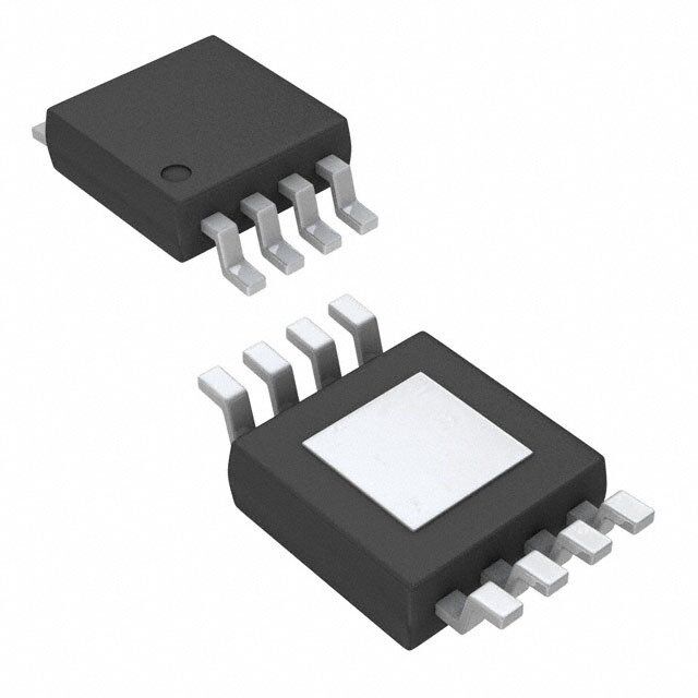
| 供应商器件封装 | 8-MSOP-PowerPad |
| 其它名称 | 296-13343-1 |
| 制造商产品页 | http://www.ti.com/general/docs/suppproductinfo.tsp?distId=10&orderablePartNumber=THS4121IDGNR |
| 包装 | 剪切带 (CT) |
| 压摆率 | 55 V/µs |
| 增益带宽积 | - |
| 安装类型 | 表面贴装 |
| 封装/外壳 | 8-TSSOP,8-MSOP(0.118",3.00mm 宽)裸焊盘 |
| 工作温度 | -40°C ~ 85°C |
| 放大器类型 | 差分 |
| 标准包装 | 1 |
| 电压-电源,单/双 (±) | 3 V ~ 3.5 V, ±1.5 V ~ 1.75 V |
| 电压-输入失调 | 3mV |
| 电流-电源 | 11mA |
| 电流-输入偏置 | 1.2pA |
| 电流-输出/通道 | 100mA |
| 电路数 | 1 |
| 输出类型 | 差分 |
| 配用 | /product-detail/zh/THS4141EVM/296-10050-ND/380597/product-detail/zh/THS4140EVM/296-10048-ND/380626/product-detail/zh/THS4121EVM/296-13560-ND/486519 |


- 商务部:美国ITC正式对集成电路等产品启动337调查
- 曝三星4nm工艺存在良率问题 高通将骁龙8 Gen1或转产台积电
- 太阳诱电将投资9.5亿元在常州建新厂生产MLCC 预计2023年完工
- 英特尔发布欧洲新工厂建设计划 深化IDM 2.0 战略
- 台积电先进制程称霸业界 有大客户加持明年业绩稳了
- 达到5530亿美元!SIA预计今年全球半导体销售额将创下新高
- 英特尔拟将自动驾驶子公司Mobileye上市 估值或超500亿美元
- 三星加码芯片和SET,合并消费电子和移动部门,撤换高东真等 CEO
- 三星电子宣布重大人事变动 还合并消费电子和移动部门
- 海关总署:前11个月进口集成电路产品价值2.52万亿元 增长14.8%


PDF Datasheet 数据手册内容提取
THS4120 THS4121 www.ti.com SLOS319D–FEBRUARY2001–REVISEDOCTOBER2004 HIGH-SPEED FULLY DIFFERENTIAL I/O AMPLIFIERS FEATURES KEY APPLICATIONS • HighPerformance • SimpleSingle-EndedToDifferential Conversion – 100MHz,–3dBBandwidth • DifferentialADCDriver/Differential – 50V/m sSlewRate Antialiasing – 75dBTotalHarmonicDistortionat1MHz • DifferentialTransmitterandReceiver (V =2V ) O PP • OutputLevelShifter – 5.4nV/(cid:214) HzInput-ReferredNoise(10kHz) • DifferentialInput/DifferentialOutput THS4120 THS4121 – BalancedOutputsRejectCommon-Mode D, DGN, OR DGK PACKAGE D, DGN, OR DGK PACKAGE Noise (TOP VIEW) (TOP VIEW) – DDiifsfteorretniotinalReducedSecondHarmonic VVOICNM− 12 87 VPIDN+ VVOICNM− 12 87 VNICN+ • PowerSupplyRange VDD 3 6 GND VDD 3 6 GND – V =3.3V VOUT+ 4 5 VOUT− VOUT+ 4 5 VOUT− DD DESCRIPTION The THS412x is one in a family of fully Table1.HIGH-SPEEDDIFFERENTIALI/OFAMILY differential-input, differential-output devices NUMBEROF DEVICE POWERDOWN fabricated using Texas Instruments' state-of-the-art CHANNELS submicronCMOSprocess. THS4120(1) 1 Yes The THS412x consists of a true, fully differential THS4121 1 – signal path from input to output. This results in excellent common-mode noise rejection and improvedtotalharmonicdistortion. (1) Forproperfunctiionality,anexternal10-kW pullupresistoris requiredbetweenthePDpinandthepositivesupply. RELATEDDEVICES SINGLESUPPLY SPLITSUPPLY DEVICE(1) DESCRIPTION VOLTAGERANGE VOLTAGERANGE THS413x 150MHz,51V/m s,1.3nV/(cid:214) Hz 5Vto30V – 2.5to– 15 THS414x 160MHz,450V/m s,6.5nV/(cid:214) Hz 5Vto30V – 2.5to– 15 THS415x 150MHz,650V/m s,7.6nV/(cid:214) Hz 5Vto30V – 2.5to– 15 (1) SeetheTIWebsiteforadditionalhigh-speedamplifierdevices. TYPICAL A/D APPLICATION CIRCUIT VDD 3.3 V VIN VOCM − + AINAVDD DVDD + − AIN AVSS Vref DIGITAL OUTPUT Pleasebeawarethatanimportantnoticeconcerningavailability,standardwarranty,anduseincriticalapplicationsofTexas Instrumentssemiconductorproductsanddisclaimerstheretoappearsattheendofthisdatasheet. PowerPADisatrademarkofTexasInstruments. PRODUCTIONDATAinformationiscurrentasofpublicationdate. Copyright©2001–2004,TexasInstrumentsIncorporated Products conform to specifications per the terms of the Texas Instruments standard warranty. Production processing does not necessarilyincludetestingofallparameters.
THS4120 THS4121 www.ti.com SLOS319D–FEBRUARY2001–REVISEDOCTOBER2004 Thesedeviceshavelimitedbuilt-inESDprotection.Theleadsshouldbeshortedtogetherorthedeviceplacedinconductivefoam duringstorageorhandlingtopreventelectrostaticdamagetotheMOSgates. AVAILABLEOPTIONS PACKAGEDDEVICES EVALUATION T MSOPPowerPAD™ MSOP A SMALLOUTLINE(D) MODULES (DGN) SYMBOL (DGK) SYMBOL THS4120CD THS4120CDGN ARL THS4120CDGK ATZ THS4120EVM 0(cid:176) Cto70(cid:176) C THS4121CD THS4121CDGN ASB THS4121CDGK ATO THS4121EVM THS4120ID THS4120IDGN ARM THS4120IDGK ARN – –40(cid:176) Cto85(cid:176) C THS4121ID THS4121IDGN ASC THS4121IDGK ASN – ABSOLUTE MAXIMUM RATINGS overoperatingfree-airtemperaturerange(unlessotherwisenoted) (1) UNIT Supplyvoltage,GNDtoV 3.6V DD V Inputvoltage – V I DD I Outputcurrent(sink) (2) 110mA O V Differentialinputvoltage – V ID DD Continuoustotalpowerdissipation SeeDissipationRatingTable T Maximumjunctiontemperature(3) 150(cid:176) C J T Maximumjunctiontemperature,continuousoperation,long-termreliability(4) 125(cid:176) C J Csuffix 0(cid:176) Cto70(cid:176) C T Operatingfree-airtemperature A Isuffix –40(cid:176) Cto85(cid:176) C T StorageTemperature –65(cid:176) Cto150(cid:176) C stg Leadtemperature1,6mm(1/16Inch)fromcasefor10seconds 300(cid:176) C HBM 4000V ESDratings CDM 1500V MM 200V (1) Stressesbeyondthoselistedunder"absolutemaximumratings”maycausepermanentdamagetothedevice.Thesearestressratings only,andfunctionaloperationofthedeviceattheseoranyotherconditionsbeyondthoseindicatedunder"recommendedoperating conditions”isnotimplied.Exposuretoabsolute-maximum-ratedconditionsforextendedperiodsmayaffectdevicereliability. (2) TheTHS412xmayincorporateaPowerPad™ontheundersideofthechip.Thisactsasaheatsinkandmustbeconnectedtoa thermallydissipativeplaneforproperpowerdissipation.Failuretodosomayresultinexceedingthemaximumjunctiontemperature whichcouldpermanentlydamagethedevice.SeeTItechnicalbriefSLMA002andSLMA004formoreinformationaboututilizingthe PowerPad™thermallyenhancedpackage. (3) Theabsolutemaximumtemperatureunderanyconditionislimitedbytheconstraintsofthesiliconprocess. (4) Themaximumjunctiontemperatureforcontinuousoperationislimitedbypackageconstraints.Operationabovethistemperaturemay resultinreducedreliabilityand/orlifetimeofthedevice. DISSIPATION RATING TABLE POWERRATING(2) PACKAGE q (1)((cid:176) C/W) q ((cid:176) C/W) JA JC T =25(cid:176) C T =85(cid:176) C A A D 97.5 38.3 1.02W 410mW DGN 58.4 4.7 1.71W 685mW DGK 260 54.2 385mW 154mW (1) ThisdatawastakenusingtheJEDECstandardHigh-KtestPCB. (2) Powerratingisdeterminedwithajunctiontemperatureof125(cid:176) C.Thisisthepointwheredistortion startstosubstantiallyincrease.ThermalmanagementofthefinalPCBshouldstrivetokeepthe junctiontemperatureatorbelow125(cid:176) Cforbestperformanceandlong-termreliability. 2 SubmitDocumentationFeedback
THS4120 THS4121 www.ti.com SLOS319D–FEBRUARY2001–REVISEDOCTOBER2004 RECOMMENDED OPERATING CONDITIONS MIN TYP MAX UNIT Splitsupply – 1.5 – 1.65 – 1.75 V Supplyvoltage V DD Singlesupply 3 3.3 3.5 Csuffix 0 70 T Operatingfree-airtemperature (cid:176) C A Isuffix –40 85 ELECTRICAL CHARACTERISTICS V =3.3V,R =800W ,T =25(cid:176) C(unlessotherwisenoted)(1) DD L A PARAMETER TESTCONDITIONS MIN TYP MAX UNIT DYNAMICPERFORMANCE BW Small-signalbandwidth(–3dB) V =3.3V, Gain=1,R =200W 100 MHz DD f SR Slewrate(2) V =3.3V, Gain=1 55 V/m s DD Settlingtimeto0.1% 60 t Differentialstepvoltage=2V ,Gain=1 ns s PP Settlingtimeto0.01% 292 DISTORTIONPERFORMANCE Totalharmonicdistortion THD Differentialinput,differentialoutput V =3.3V, f=1MHz –75 dB DD Gain=1,R =200W ,R =800W ,V =2V f L O PP Totalharmonicdistortion THD Differentialinput,differentialoutput V =3.3V, f=1MHz –66 dB DD Gain=1,R =200W ,R =800W ,V =4V f L O PP Spuriousfreedynamicrange(SFDR) R =200W , f=1MHz –69 dB Differentialinput,differentialoutput,V =4V f O PP Thirdintermodulationdistortion V =0.071V Gain=1,f=10MHz –75 dBc I RMS NOISEPERFORMANCE V Inputvoltagenoise f=10kHz 5.4 nV/(cid:214) Hz n I Inputcurrentnoise f=10kHz 1 fA/(cid:214) Hz n DCPERFORMANCE T =25(cid:176) C 60 66 A Open-loopgain dB T =fullrange 66 A T =25(cid:176) C 3 8 A Inputoffsetvoltage T =fullrange 4 9 A mV V T =25(cid:176) C 5 13 S A Inputoffsetvoltage,referredtoV OCM T =fullrange 14 A Offsetvoltagedrift T =fullrange 25 m V/(cid:176) C A I Inputbiascurrent 1.2 pA IB T =fullrange A I Inputoffsetcurrent 100 fA OS Currentoffsetdrift T =fullrange 5 fA/(cid:176) C A (1) Thefullrangetemperatureis0(cid:176) Cto70(cid:176) CfortheCsuffix,and–40(cid:176) Cto85(cid:176) CfortheIsuffix. (2) Slewrateismeasureddifferentiallyfromanoutputlevelrangeof25%to75%. SubmitDocumentationFeedback 3
THS4120 THS4121 www.ti.com SLOS319D–FEBRUARY2001–REVISEDOCTOBER2004 ELECTRICAL CHARACTERISTICS (Continued) V =3.3V,R =800W ,T =25(cid:176) C(unlessotherwisenoted)(1) DD L A PARAMETER TESTCONDITIONS MIN TYP MAX UNIT INPUTCHARACTERISTICS CMRR Common-moderejectionratio T =fullrange 64 96 dB A 0.35 0.65to V Common-modeinputvoltagerange T =fullrange to V ICR A V –0.1 DD V DD r Inputresistance(dclevel) Measuredintoeachinputterminal 820 MW i C Inputcapacitance,closedloop 3 pF i r Outputresistance SeeFigure16 1 W o OUTPUTCHARACTERISTICS V High-leveloutputVoltage V =V /2,V =3.3V, T =25(cid:176) C 3.05 3.15 V OH IC DD DD A V Low-leveloutputVoltage V =V /2,V =3.3V, T =25(cid:176) C 0.25 0.15 V OL IC DD DD A I Outputcurrent(sink),R =7W V =3.3V, T =25(cid:176) C 80 100 mA O L DD A I Outputcurrent(source),R =7W V =3.3V, T =25(cid:176) C 20 25 mA O L DD A POWERSUPPLY V Supplyvoltagerange Singlesupply 3.3 V DD T =25(cid:176) C 11 13.5 A I Quiescentcurrent(peramplifier) V =3.3V mA DD DD T =fullrange 16 A PSRR Power-supplyrejectionratio T =25(cid:176) C 68 85 dB A POWER-DOWNCHARACTERISTICS(THS4120ONLY) Enable >1.4 Power-downvoltagelevel(2) V Powerdown <1.2 T =25(cid:176) C 120 Power-downquiescentcurrent A m A T =fullrange 130 A t Turn-ontimedelay 4.8 m s on 50%offinalsupplycurrentvalue t Turn-offtimedelay 3 ns off z Outputimpedance f=1MHz 1 kW o (1) Thefullrangetemperatureis0(cid:176) Cto70(cid:176) CfortheCsuffix,and–40(cid:176) Cto85(cid:176) CfortheIsuffix. (2) Fordetailinformationonthepower-downcircuit,seethepower-downsectionintheapplicationsectionofthisdatasheet. TYPICAL CHARACTERISTICS Table of Graphs FIGURE Small-signalfrequencyresponse 1 SR Slewrate 2 vsFrequency 3 THD Totalharmonicdistortion vsOutputvoltage 4 vsFrequency 5,6,7 Harmonicdistortion vsOutputvoltage 8,9 Thirdintermodulationdistortion vsOutputvoltage 10 V Outputvoltage vsLoadresistance 11 O Settlingtime 12 V Voltagenoise vsFrequency 13 n V Outputoffsetvoltage vsCommon-modeinputvoltage 14 OO CMMR Common-moderejectionratio vsFrequency 15 z Single-endedoutputimpedance(closedloop) vsFrequency 16 os 4 SubmitDocumentationFeedback
THS4120 THS4121 www.ti.com SLOS319D–FEBRUARY2001–REVISEDOCTOBER2004 TYPICAL CHARACTERISTICS (continued) FIGURE z Single-ended(V )inputimpedance vsFrequency 17 o OCM SMALL-SIGNALFREQUENCYRESPONSE SLEWRATE 2 1.5 Rf = 390 W Falling Edge 1 Rf = 270 W 1 0 Rf = 200 W e − V 0.5 VVDOD = = 2 3 V.3P PV,, ain − dB −1 Rf = 150 W put Voltag 0 TGRAL == = 12 850°0C W G ut O −2 − −0.5 O V −3 G = 1 −1 Rising Edge VI = 22.5 mVRMS VDD = 3.3 V −4 −1.5 100 k 1M 10 M 100 M 1G 0 20 40 60 80 f − Frequency − Hz t − Time − ns Figure1. Figure2. TOTALHARMONICDISTORTION TOTALHARMONICDISTORTION vs vs FREQUENCY OUTPUTVOLTAGE −20 −50 VDD = 3.3 V, VDD = 3.3 V, Single Input / VO = 4 VPP f = 1 MHz Differential Output n − dB −30 RRGfL = == 1 280000 WW , n − dB −60 RRfL == 280000 WW , o o orti −40 orti st st Differential Input / c Di Single−Ended Input / c Di Differential Output oni −50 Differential Output oni −70 m m ar ar H H al −60 al ot ot − T − T −80 D D H −70 H T Differential Input/ T Differential Output −80 −90 100 k 1 M 10 M 0 1 2 3 4 5 f − Frequency − Hz VO − Output Voltage − V Figure3. Figure4. SubmitDocumentationFeedback 5
THS4120 THS4121 www.ti.com SLOS319D–FEBRUARY2001–REVISEDOCTOBER2004 THS4121 THS4121 TOTALHARMONICDISTORTION HARMONICDISTORTION vs vs FREQUENCY FREQUENCY −40 −30 VDD = 3.3 V, VDD = 3.3 V, VO = 2 VPP, VO = 4 VPP, −50 RL = 800 W , −40 RL = 800 W , 3rd_HD Rf = 270 W , 5th_HD Rf = 200 W , −50 B −60 G = 1 B G = 1 d d − − −60 2nd_HD n −70 233nrrddd___HHHDDD n o o orti orti −70 st −80 st Di Di c c −80 oni −90 oni m m −90 ar ar 5th_HD H −100 3rd_HD H 4th_HD −100 −110 Differential Input / −110 Differential Input / 4th_HD Differential Output Differential Output −120 −120 100 k 1 M 10 M 100 k 1 M 10 M f − Frequency − Hz f − Frequency − Hz Figure5. Figure6. THS4121 THS4121 HARMONICDISTORTION HARMONICDISTORTION vs vs FREQUENCY OUTPUTVOLTAGE −20 −60 VDD = 3.3 V, VDD = 3.3 V, VO = 4 VPP, f = 1 MHz, −30 RL = 800 W , −70 RL = 800 W , 2nd_HD Rf = 200 W , Rf = 200 W , B −40 G = 1 B G = 1 d d − 2nd_HD − −80 n −50 n 3rd_HD o o orti 3rd_HD orti st −60 st −90 Di Di c c oni −70 oni m m −100 ar 5th_HD ar H −80 H 4th_HD −110 −90 Differential Input / Single Input / Differential Output Differential Output −100 −120 100 k 1 M 10 M 0 0.5 1 1.5 2 2.5 3 3.5 4 4.5 5 f − Frequency − Hz VO − Output Voltage − V Figure7. Figure8. 6 SubmitDocumentationFeedback
THS4120 THS4121 www.ti.com SLOS319D–FEBRUARY2001–REVISEDOCTOBER2004 THS4121 HARMONICDISTORTION THIRDINTERMODULALTIONDISTORTION vs vs OUTPUTVOLTAGE OUTPUTVOLTAGE −60 −10 VDD = 3.3 V, VDD = 3.3 V, f = 1 MHz, 2nd_HD f = 1 MHz B −70 RRGLf = == 1 280000 WW ,, n − dBc −−3200 RRfL == 287000 WW , d o on − −80 3rd_HD storti −40 f = 10 MHz rti Di nic Disto −90 4th_HD dulation −50 o o −60 m −100 m ar 5th_HD er H d Int −70 f = 5 MHz r −110 hi T −80 Single Input / Differential Output −120 −90 0 0.5 1 1.5 2 2.5 3 3.5 4 4.5 −25 −20 −15 −10 −5 0 5 10 VO − Output Voltage − V VO − Output Voltage − V Figure9. Figure10. THS4121 OUTPUTVOLTAGE vs LOADRESISTANCE SETTLINGTIME 2 1.03 1.5 VDD = 3.3 V 1.02 VVRDOF D == = 32 33 V0.3P W PV,,, Sink RL = 800 W , 1 V 1.01 G = 1 V − − e oltage 0.5 Voltag 1 ut V 0 put 0.99 p ut Out −0.5 − O 0.98 − O O V Settling Time, V −1 0.97 1% = 40 ns, 0.1% = 60 ns, Source −1.5 0.01% = 292 ns 0.96 −2 0.95 100 1k 10k 0 100 200 300 400 500 RL − Load Resistance − W t − Time − ns Figure11. Figure12. SubmitDocumentationFeedback 7
THS4120 THS4121 www.ti.com SLOS319D–FEBRUARY2001–REVISEDOCTOBER2004 VOLTAGENOISE OUTPUTOFFSETEVOLTAGE vs vs FREQUENCY COMMON-MODEINPUTVOLTAGE 140 0.1 120 z H V 0 nV/ 100 ge − e − olta s V −0.1 Noi 80 et ge Offs Volta 60 put −0.2 − ut O Vn 40 − O O V −0.3 20 0 −0.4 1 10 100 1 k 10 k 100 k 0 0.5 1 1.5 2 2.5 3 f − Frequency − Hz VIC− Common-Mode Input Voltage − V Figure13. Figure14. THS4121 THS4121 COMMON-MODEREJECTIONRATIO SINGLE-ENDEDOUTPUTIMPEDANCE vs vs FREQUENCY FREQUENCY −50 1000 B VDD = 3.3 V, VDD = 3.3 V, − d Rf = 1 kW , VI = 5 dBm atio −60 RGL = = 1 800 W , We − G = 1 R c n an o d cti −70 pe 100 e m e Rej put I od −80 ut M O mmon- −90 Ended 10 o e- C gl − n RR −100 − Si M s C o z −110 1 100 k 1 M 10 M 100 M 100 k 1 M 10 M 100 M f − Frequency − Hz f − Frequency − Hz Figure15. Figure16. 8 SubmitDocumentationFeedback
THS4120 THS4121 www.ti.com SLOS319D–FEBRUARY2001–REVISEDOCTOBER2004 THS4121 SINGLE-ENDED(V )INPUTIMPEDANCE OCM vs FREQUENCY 1 M VDD = 3.3 V, We − VI = −0.071 V(RMS) c n a 100 k d e p m ut I p 10 k n I) M C O V ( 1 k d e d n E e- gl 100 n Si − s i Z 10 100 k 1 M 10 M 100 M 1 G f − Frequency − Hz Figure17. SubmitDocumentationFeedback 9
THS4120 THS4121 www.ti.com SLOS319D–FEBRUARY2001–REVISEDOCTOBER2004 APPLICATION INFORMATION RESISTOR MATCHING Resistor matching is important in fully differential amplifiers. The balance of the output on the reference voltage depends on matched ratios of the resistors. CMRR, PSRR, and cancellation of the second harmonic distortion diminish if resistor mismatch occurs. Therefore, it is recommended to use 1% tolerance resistors or better to keeptheperformanceoptimized. V setsthedcleveloftheoutputsignals.IfnovoltageisappliedtotheV pin,itissettothemidrailvoltage OCM OCM internallydefinedas: (cid:2)VDD(cid:3) (cid:1) (cid:2)VSS(cid:3) 2 (1) In the differential mode, the V on the two outputs cancel each other. Therefore, the output in the differential OCM mode is the same as the input with the gain of 1. V has a high bandwidth capability up to the typical OCM operation range of the amplifier. For the prevention of noise going through the device, use a 0.1-m F capacitor on theV pinasabypasscapacitor.ThefollowinggraphshowsthesimplifieddiagramoftheTHS412x. OCM VDD Output Buffer VIN- x1 VOUT+ C R VIN+ Vcm Error Amplifier + _ C R x1 VOUT- Output Buffer VDD 30 kW VSS 30 kW VSS VOCM Figure18.THS412xSimplifiedDiagram 10 SubmitDocumentationFeedback
THS4120 THS4121 www.ti.com SLOS319D–FEBRUARY2001–REVISEDOCTOBER2004 APPLICATION INFORMATION (continued) DATA CONVERTERS Dataconvertersareoneofthemostpopularapplicationsforthefullydifferentialamplifiers. Fully differential amplifiers can operate with a single supply. V defaults to the midrail voltage, V /2. The OCM DD differential output may be fed into a data converter. This method eliminates the use of a transformer in the circuit. If the ADC has a reference voltage output (V ), then it is recommended to connect it directly to the V ref OCM of the amplifier using a bypass capacitor for stability. For proper operation, the input common-mode voltage to theinputterminaloftheamplifiershouldnotexceedthecommon-modeinputvoltagerange. 3.3 V VDD 3.3 V VIN + - AVDD DVDD VOCM AIN1 0.1 m F - + AIN2AVSS Vref Figure19.DifferentialAmplifierUsingaSingleSupply Somesingle-supplyapplicationsmayrequiretheinput voltage to exceed the common-mode input voltage range. Insuchcases,thefollowingcircuitconfigurationis suggested to bring the common-mode input voltage within the specificationsoftheamplifier. VCC VDD Rf VDD RPU 3.3 V VIN R(g) + - VOUT AVDD DVDD VP VOCM AIN1 0.1 m F - + AIN2AVSS Vref R(g) VOUT RPU VCC Rf Figure20.CircuitWithImprovedCommon-ModeInputVoltage ThefollowingequationisusedtocalculateR : PU V –V P DD RPU (cid:2) (cid:3)VIN–VP(cid:4)R1 (cid:1) (cid:3)VOUT–VP(cid:4)R1 (g) f (2) SubmitDocumentationFeedback 11
THS4120 THS4121 www.ti.com SLOS319D–FEBRUARY2001–REVISEDOCTOBER2004 APPLICATION INFORMATION (continued) DRIVING A CAPACITIVE LOAD Driving capacitive loads with high-performance amplifiers is not a problem as long as certain precautions are taken. The first is to realize that the THS412x has been internally compensated to maximize its bandwidth and slew rate performance. When the amplifier is compensated in this manner, capacitive loading directly on the output decreases the device's phase margin leading to high-frequency ringing or oscillations. Therefore, for capacitive loads of greater than 10 pF, it is recommended that a resistor be placed in series with the output of the amplifier, as shown in Figure 21. A minimum value of 20 W should work well for most applications. For example, in 50-W transmission systems, setting the series resistor value to 50 W both isolates any capacitance loadingandprovidestheproperlineimpedancematchingatthesourceend. Rf 20 W R(g) Output THS412x 20 W R(g) Output Rf Figure21.DrivingaCapacitiveLoad ACTIVE ANTIALIAS FILTERING For signal conditioning in ADC applications, it is important to limit the input frequency to the ADC. Low-pass filters can prevent the aliasing of the high-frequency noise with the frequency of operation. Figure 22 presents a methodbywhichthenoisemaybefilteredintheTHS412x.Propergroundreferencingshouldbeconsidered. R2 C1 VDD R4 VDD C3 R1 R3 VIN- - + VIN+AVDD DVDD Vs C2 THS412x R(t) VIN+ + - VIN- VOCM R1 R3 VOCM C3 VIC R4 VSS C1 R2 Figure22.AntialiasFiltering 12 SubmitDocumentationFeedback
THS4120 THS4121 www.ti.com SLOS319D–FEBRUARY2001–REVISEDOCTOBER2004 APPLICATION INFORMATION (continued) Thetransferfunctionforthisfiltercircuitis: (cid:5) (cid:7) (cid:5) Rt (cid:7) Hd(f)(cid:2)(cid:9)(cid:9) 2 K (cid:9)(cid:9)x(cid:9) 2Rj24p (cid:1)fR4RRttC3(cid:9) WhereK(cid:2) RR21 (cid:6)–(cid:3)FSFfxfc(cid:4) (cid:1) Q1 FSFjfxfc (cid:1) 1(cid:8) (cid:6)1 (cid:1) 2R4(cid:1)Rt(cid:8) (3) 1 (cid:3)2xR2R3C1C2 FSFxfc (cid:2) and Q (cid:2) 2p (cid:3)2xR2R3C1C2 R3C1 (cid:1) R2C1 (cid:1) KR3C1 (4) K sets the pass-band gain, fc is the cutoff frequency for the filter, FSF is a frequency scaling factor, and Q is the qualityfactor. FSF (cid:2) (cid:3)Re2 (cid:1) |Im|2 andQ (cid:2) (cid:3)Re2 (cid:1) |Im|2 2Re (5) Where Re is the real part, and Im is the imaginary part of the complex pole pair. Setting R2 = R, R3 = mR, C1=C,andC2=nCresultsin: 1 (cid:3)2xmn FSFxfc (cid:2) andQ (cid:2) 2p RC(cid:3)2xmn 1 (cid:1) m(1(cid:1)K) (6) Startbydeterminingtheratios,mandn,requiredforthegainand Q of the filter type being designed, then select CandcalculateRforthedesiredfc. PRINCIPLES OF OPERATION THEORY OF OPERATION The THS412x is a fully differential amplifier. Differential amplifiers are typically differential in/single out, whereas fullydifferentialamplifiersaredifferentialin/differentialout. Differential Amplifier THS412x Rf Fully Differential Amplifier VDD R(g) _ VIN− _ + VO+ _ + VIN+ + VO− R(g) Rf VOCM GND Figure23.DifferentialAmplifierVersusaFullyDifferentialAmplifier To understand the THS412x fully differential amplifiers, the definition for the pinouts of the amplifier are provided. Inputvoltagedefinition VID (cid:2) (cid:3)VI(cid:1)(cid:4)– (cid:3)VI–(cid:4) VIC (cid:2) (cid:3)VI(cid:1)(cid:4) (cid:1)2 (cid:3)VI–(cid:4) (7) Outputvoltagedefinition VOD (cid:2) (cid:3)VO(cid:1)(cid:4)– (cid:3)VO–(cid:4) VOC (cid:2) (cid:3)VO(cid:1)(cid:4) (cid:1)2 (cid:3)VO–(cid:4) (8) Transferfunction VOD (cid:1) VID x A(cid:2)f(cid:3) (9) Outputcommon−modevoltage V OC (10) SubmitDocumentationFeedback 13
THS4120 THS4121 www.ti.com SLOS319D–FEBRUARY2001–REVISEDOCTOBER2004 PRINCIPLES OF OPERATION (continued) Differential Structure Rejects Differential Structure Rejects Coupled Noise at the Input Coupled Noise at the Output VDD _ VIN- + VO+ _ VIN+ + VO- Differential Structure Rejects VOCM Coupled Noise at the Power Supply GND Figure24.DefinitionoftheFullyDifferentialAmplifier The following schematics depict the differences between the operation of the THS412x, fully differential amplifier, in two different modes. Fully differential amplifiers can work with differential input or can be implementedassinglein/differentialout. Rf VDD VIN- R(g) - + VO+ Vs VIN+ +- VO- Note: For proper operation, maintain R(g) VOCM symmetry by setting GND Rf1 = Rf2 = Rf and R(g)1 = R(g)2 = R(g) ⇒ A = Rf/R(g) Rf Figure25.AmplifyingDifferentialSignals Rf VDD VIN- R(g) RECOMMENDED RESISTOR VALUES - + VO+ GAIN R(g) W Rf W VIN+ +- VO- 1 150 150 R(g) VOCM Vs GND Rf Figure26.SingleInWithDifferentialOut If each output is measured independently, each output is one-half of the input signal when gain is 1. The followingequationsexpressthetransferfunctionforeachoutput: V (cid:1) 1 V O 2 I (11) Thesecondoutputisequalandoppositeinsign: V (cid:1) –1 V O 2 I (12) 14 SubmitDocumentationFeedback
THS4120 THS4121 www.ti.com SLOS319D–FEBRUARY2001–REVISEDOCTOBER2004 PRINCIPLES OF OPERATION (continued) Fully differential amplifiers may be viewed as two inverting amplifiers. In this case, the equation of an inverting amplifier holds true for gain calculations. One advantage of fully differential amplifiers is that they offer twice as much dynamic range compared to single-ended amplifiers. For example, a 1-V ADC can only support an input PP signal of 1 V . If the output of the amplifier is 2 V , then it is not practical to feed a 2-V signal into the PP PP PP targeted ADC. Using a fully differential amplifier enables the user to break down the output into two 1-V PP signals with opposite signs and feed them into the differential input nodes of the ADC. In practice, the designer has been able to feed a 2-V peak-to-peak signal into a 1-V differential ADC with the help of a fully differential amplifier. The final result indicates twice as much dynamic range. Figure 27 illustrates the increase in dynamic range. The gain factor should be considered in this scenario. The THS412x fully differential amplifier offers an improved CMRR and PSRR due to its symmetrical input and output. Furthermore, second harmonic distortion is improved.Secondharmonicstendtocancelbecauseofthesymmetricaloutput. a VOD= 1-0 = 1 VDD +1 _ VIN- + VO+ 0 _ VIN+ + VO- +1 VOCM 0 VSS b VOD = 0-1 = -1 Figure27.FullyDifferentialAmplifierWithTwo1-V Signals PP CIRCUIT LAYOUT CONSIDERATIONS To achieve the levels of high-frequency performance of the THS412x, follow proper printed-circuit board high frequency design techniques. A general set of guidelines is given below. In addition, a THS412x evaluation boardisavailabletouseasaguideforlayoutorforevaluatingthedeviceperformance. • Groundplanes-Itishighlyrecommendedthatagroundplanebeusedontheboardtoprovideallcomponentswithalow inductivegroundconnection.However,intheareasoftheamplifierinputsandoutput,thegroundplanecanbe removed tominimizethestraycapacitance. • Proper power supply decoupling - Use a 6.8-m F tantalum capacitor in parallel with a 0.1-m F ceramic capacitor on each supply terminal. It may be possible to share the tantalum among several amplifiers depending on the application, but a 0.1-m F ceramic capacitor should always be used on the supply terminal of every amplifier. In addition, the 0.1-m F capacitorshouldbe placed as close as possible to the supply terminal. As this distance increases, the inductance in the connecting trace makes the capacitor less effective. The designer should strive for distances of less than 0.1 inch (2,54 mm)betweenthedevicepowerterminalsandtheceramiccapacitors. • Sockets - Sockets are not recommended for high-speed operational amplifiers. The additional lead inductance in the socket pins often lead to stability problems. Surface-mount packages soldered directly to the printed-circuit board is the bestimplementation. • Short trace runs/compact part placements - Optimum high-frequency performance is achieved when stray series inductance has been minimized. To realize this, the circuit layout should be made as compact as possible, thereby minimizingthelengthofalltraceruns.Particularattentionshouldbepaidtotheinvertinginputoftheamplifier. Its length shouldbekeptasshortaspossible.Thishelpstominimizestraycapacitanceattheinputoftheamplifier. • Surface-mount passive components - Using surface-mount passive components is recommended for high-frequency amplifier circuits for several reasons. First, because of the extremely low lead inductance of surface-mount components, the problem with stray series inductance is greatly reduced. Second, the small size of surface-mount components naturally leads to a more compact layout thereby minimizing both stray inductance and capacitance. If leaded componentsareused,itisrecommendedthattheleadlengthsbekeptasshortaspossible. POWER-DOWN MODE The THS4120 features a power-down pin (PD) which lowers the quiescent current from 11 mA down to 120 m A, ideal for reducing system power. The power-down pin of the amplifier must be pulled high via a 10-kW pullup resistorbetweenthePDpinandthepositivesupply(seeFigure28) in the absence of an applied voltage, putting SubmitDocumentationFeedback 15
THS4120 THS4121 www.ti.com SLOS319D–FEBRUARY2001–REVISEDOCTOBER2004 PRINCIPLES OF OPERATION (continued) theamplifierinthepower-onmodeofoperation.Toturnoff(disable) the amplifier in an effort to conserve power, the power-down pin can be driven towards the negative rail or ground. The threshold voltages for power-on and power-down are relative to the supply rails and given in the specification tables. Above the Enable Threshold Voltage, the device is on. Below the Disable Threshold Voltage, the device is off. Behavior in between these thresholdvoltagesisnotspecified. Notethatthispower-downfunctionalityisjust that; the amplifier consumes less power in power-down mode. The power-down mode is not intended to provide a high-impedance output. The power-down functionality is not intended to allow use as a 3-state bus driver. When in power-down mode, the impedance looking back into the output of the amplifier is dominated by the feedback and gain-setting resistors, but the output impedance of the deviceitselfvariesdependingonthevoltageappliedtotheoutputs. The time delays associated with turning the device on and off are specified as the time it takes for the amplifier to reach 50% of the nominal quiescent current. The enable time delay is in the order of microseconds due to the amplifiermovinginandoutofthelinearmodeofoperation. 3.3 V PD 10 k(cid:1) + THS4120 _ VIN VOCM Figure28. Due to the similarity of the standard inverting amplifier configuration, the output impedance appears to be low while in the power-down state. This is because the feedback resistor (R) and the gain resistor (R ) are still f (g) connected to the circuit. Therefore, a current path is allowed between the input of the amplifier and the output of theamplifier.Anexampleoftheclosed-loopoutputimpedanceisshowninFigure29. 16 SubmitDocumentationFeedback
THS4120 THS4121 www.ti.com SLOS319D–FEBRUARY2001–REVISEDOCTOBER2004 PRINCIPLES OF OPERATION (continued) THS4120 SINGLE-ENDED OUTPUT IMPEDANCE (IN POWER DOWN) vs FREQUENCY W− n) 10000 w VCC = 3.3 V o D er w o P n e (i 1000 c n a d e p m ut I p ut 100 O d e d n E e- gl n Si − 10 s o 100 k 1 M 10 M 100 M 1 G z f − Frequency − Hz Figure29. SubmitDocumentationFeedback 17
THS4120 THS4121 www.ti.com SLOS319D–FEBRUARY2001–REVISEDOCTOBER2004 PRINCIPLES OF OPERATION (continued) GENERAL PowerPAD DESIGN CONSIDERATIONS (APPLICABLE TO DIFFERENTIAL AMPLIFIER FAMILY) The THS412x is available packaged in a thermally enhanced DGN package, which is a member of the PowerPAD family of packages. This package is constructed using a downset leadframe on which the die is mounted [see Figure 30(a) and Figure 30(b)]. This arrangement results in the leadframe being exposed as a thermal pad on the underside of the package [see Figure 30(c)]. Because this thermal pad has direct thermal contact with the die, excellent thermal performance can be achieved by providing a good thermal path away fromthethermalpad. The PowerPAD package allows for both assembly and thermal management in one manufacturing operation. During the surface-mount solder operation (when the leads are being soldered), the thermal pad can also be soldered to a copper area underneath the package. Through the use of thermal paths within this copper area, heatcanbeconductedawayfromthepackageintoeitheragroundplaneorotherheat-dissipatingdevice. The PowerPAD package represents a breakthrough in combining the small area and ease of assembly of the surfacemountwiththe,heretofore,awkwardmechanicalmethodsofheatsinking. More complete details of the PowerPAD installation process and thermal management techniques can be found in the Texas Instruments Technical Brief, PowerPAD Thermally Enhanced Package (SLMA002). This document can be found at the TI Web site (www.ti.com) by searching on the key word PowerPAD. The document can also beorderedthroughyourlocalTIsalesoffice.RefertoliteraturenumberSLMA002whenordering. DIE Side View (a) Thermal Pad DIE End View (b) Bottom View (c) A. Thethermalpadiselectricallyisolatedfromallterminalsinthepackage. Figure30.ViewsofThermallyEnhancedDGNPackage 18 SubmitDocumentationFeedback
PACKAGE OPTION ADDENDUM www.ti.com 6-Feb-2020 PACKAGING INFORMATION Orderable Device Status Package Type Package Pins Package Eco Plan Lead/Ball Finish MSL Peak Temp Op Temp (°C) Device Marking Samples (1) Drawing Qty (2) (6) (3) (4/5) THS4120CD ACTIVE SOIC D 8 75 Green (RoHS NIPDAU Level-1-260C-UNLIM 0 to 70 4120C & no Sb/Br) THS4120CDGN ACTIVE HVSSOP DGN 8 80 Green (RoHS NIPDAU Level-1-260C-UNLIM 0 to 70 ARL & no Sb/Br) THS4120ID ACTIVE SOIC D 8 75 Green (RoHS NIPDAU Level-1-260C-UNLIM -40 to 85 4120I & no Sb/Br) THS4120IDGK ACTIVE VSSOP DGK 8 80 Green (RoHS NIPDAU Level-1-260C-UNLIM -40 to 85 ARN & no Sb/Br) THS4120IDGN ACTIVE HVSSOP DGN 8 80 Green (RoHS NIPDAU Level-1-260C-UNLIM -40 to 85 ARM & no Sb/Br) THS4120IDGNR ACTIVE HVSSOP DGN 8 2500 Green (RoHS NIPDAU Level-1-260C-UNLIM -40 to 85 ARM & no Sb/Br) THS4120IDR ACTIVE SOIC D 8 2500 Green (RoHS NIPDAU Level-1-260C-UNLIM -40 to 85 4120I & no Sb/Br) THS4121CD ACTIVE SOIC D 8 75 Green (RoHS NIPDAU Level-1-260C-UNLIM 0 to 70 4121C & no Sb/Br) THS4121CDGK ACTIVE VSSOP DGK 8 80 Green (RoHS Call TI | NIPDAU Level-1-260C-UNLIM 0 to 70 ATO & no Sb/Br) THS4121CDGKR ACTIVE VSSOP DGK 8 2500 Green (RoHS Call TI | NIPDAU Level-1-260C-UNLIM 0 to 70 ATO & no Sb/Br) THS4121CDGN ACTIVE HVSSOP DGN 8 80 Green (RoHS NIPDAU Level-1-260C-UNLIM 0 to 70 ASB & no Sb/Br) THS4121ID ACTIVE SOIC D 8 75 Green (RoHS NIPDAU Level-1-260C-UNLIM -40 to 85 4121I & no Sb/Br) THS4121IDGK ACTIVE VSSOP DGK 8 80 Green (RoHS Call TI | NIPDAU Level-1-260C-UNLIM 0 to 70 ASN & no Sb/Br) THS4121IDGKR ACTIVE VSSOP DGK 8 2500 Green (RoHS Call TI | NIPDAU Level-1-260C-UNLIM 0 to 70 ASN & no Sb/Br) THS4121IDGKRG4 ACTIVE VSSOP DGK 8 2500 Green (RoHS Call TI Level-1-260C-UNLIM 0 to 70 ASN & no Sb/Br) THS4121IDGN ACTIVE HVSSOP DGN 8 80 Green (RoHS NIPDAU | NIPDAUAG Level-1-260C-UNLIM -40 to 85 ASC & no Sb/Br) THS4121IDGNG4 ACTIVE HVSSOP DGN 8 80 Green (RoHS NIPDAUAG Level-1-260C-UNLIM -40 to 85 ASC & no Sb/Br) Addendum-Page 1
PACKAGE OPTION ADDENDUM www.ti.com 6-Feb-2020 Orderable Device Status Package Type Package Pins Package Eco Plan Lead/Ball Finish MSL Peak Temp Op Temp (°C) Device Marking Samples (1) Drawing Qty (2) (6) (3) (4/5) THS4121IDGNR ACTIVE HVSSOP DGN 8 2500 Green (RoHS NIPDAU | NIPDAUAG Level-1-260C-UNLIM -40 to 85 ASC & no Sb/Br) (1) The marketing status values are defined as follows: ACTIVE: Product device recommended for new designs. LIFEBUY: TI has announced that the device will be discontinued, and a lifetime-buy period is in effect. NRND: Not recommended for new designs. Device is in production to support existing customers, but TI does not recommend using this part in a new design. PREVIEW: Device has been announced but is not in production. Samples may or may not be available. OBSOLETE: TI has discontinued the production of the device. (2) RoHS: TI defines "RoHS" to mean semiconductor products that are compliant with the current EU RoHS requirements for all 10 RoHS substances, including the requirement that RoHS substance do not exceed 0.1% by weight in homogeneous materials. Where designed to be soldered at high temperatures, "RoHS" products are suitable for use in specified lead-free processes. TI may reference these types of products as "Pb-Free". RoHS Exempt: TI defines "RoHS Exempt" to mean products that contain lead but are compliant with EU RoHS pursuant to a specific EU RoHS exemption. Green: TI defines "Green" to mean the content of Chlorine (Cl) and Bromine (Br) based flame retardants meet JS709B low halogen requirements of <=1000ppm threshold. Antimony trioxide based flame retardants must also meet the <=1000ppm threshold requirement. (3) MSL, Peak Temp. - The Moisture Sensitivity Level rating according to the JEDEC industry standard classifications, and peak solder temperature. (4) There may be additional marking, which relates to the logo, the lot trace code information, or the environmental category on the device. (5) Multiple Device Markings will be inside parentheses. Only one Device Marking contained in parentheses and separated by a "~" will appear on a device. If a line is indented then it is a continuation of the previous line and the two combined represent the entire Device Marking for that device. (6) Lead/Ball Finish - Orderable Devices may have multiple material finish options. Finish options are separated by a vertical ruled line. Lead/Ball Finish values may wrap to two lines if the finish value exceeds the maximum column width. Important Information and Disclaimer:The information provided on this page represents TI's knowledge and belief as of the date that it is provided. TI bases its knowledge and belief on information provided by third parties, and makes no representation or warranty as to the accuracy of such information. Efforts are underway to better integrate information from third parties. TI has taken and continues to take reasonable steps to provide representative and accurate information but may not have conducted destructive testing or chemical analysis on incoming materials and chemicals. TI and TI suppliers consider certain information to be proprietary, and thus CAS numbers and other limited information may not be available for release. In no event shall TI's liability arising out of such information exceed the total purchase price of the TI part(s) at issue in this document sold by TI to Customer on an annual basis. Addendum-Page 2
PACKAGE MATERIALS INFORMATION www.ti.com 6-Sep-2019 TAPE AND REEL INFORMATION *Alldimensionsarenominal Device Package Package Pins SPQ Reel Reel A0 B0 K0 P1 W Pin1 Type Drawing Diameter Width (mm) (mm) (mm) (mm) (mm) Quadrant (mm) W1(mm) THS4120IDGNR HVSSOP DGN 8 2500 330.0 12.4 5.3 3.4 1.4 8.0 12.0 Q1 THS4120IDR SOIC D 8 2500 330.0 12.4 6.4 5.2 2.1 8.0 12.0 Q1 THS4121CDGKR VSSOP DGK 8 2500 330.0 12.4 5.3 3.4 1.4 8.0 12.0 Q1 THS4121IDGKR VSSOP DGK 8 2500 330.0 12.4 5.3 3.4 1.4 8.0 12.0 Q1 THS4121IDGNR HVSSOP DGN 8 2500 330.0 12.4 5.3 3.4 1.4 8.0 12.0 Q1 THS4121IDGNR HVSSOP DGN 8 2500 330.0 12.4 5.3 3.4 1.4 8.0 12.0 Q1 PackMaterials-Page1
PACKAGE MATERIALS INFORMATION www.ti.com 6-Sep-2019 *Alldimensionsarenominal Device PackageType PackageDrawing Pins SPQ Length(mm) Width(mm) Height(mm) THS4120IDGNR HVSSOP DGN 8 2500 358.0 335.0 35.0 THS4120IDR SOIC D 8 2500 350.0 350.0 43.0 THS4121CDGKR VSSOP DGK 8 2500 358.0 335.0 35.0 THS4121IDGKR VSSOP DGK 8 2500 358.0 335.0 35.0 THS4121IDGNR HVSSOP DGN 8 2500 358.0 335.0 35.0 THS4121IDGNR HVSSOP DGN 8 2500 364.0 364.0 27.0 PackMaterials-Page2
PACKAGE OUTLINE D0008A SOIC - 1.75 mm max height SCALE 2.800 SMALL OUTLINE INTEGRATED CIRCUIT C SEATING PLANE .228-.244 TYP [5.80-6.19] .004 [0.1] C A PIN 1 ID AREA 6X .050 [1.27] 8 1 2X .189-.197 [4.81-5.00] .150 NOTE 3 [3.81] 4X (0 -15 ) 4 5 8X .012-.020 B .150-.157 [0.31-0.51] .069 MAX [3.81-3.98] .010 [0.25] C A B [1.75] NOTE 4 .005-.010 TYP [0.13-0.25] 4X (0 -15 ) SEE DETAIL A .010 [0.25] .004-.010 0 - 8 [0.11-0.25] .016-.050 [0.41-1.27] DETAIL A (.041) TYPICAL [1.04] 4214825/C 02/2019 NOTES: 1. Linear dimensions are in inches [millimeters]. Dimensions in parenthesis are for reference only. Controlling dimensions are in inches. Dimensioning and tolerancing per ASME Y14.5M. 2. This drawing is subject to change without notice. 3. This dimension does not include mold flash, protrusions, or gate burrs. Mold flash, protrusions, or gate burrs shall not exceed .006 [0.15] per side. 4. This dimension does not include interlead flash. 5. Reference JEDEC registration MS-012, variation AA. www.ti.com
EXAMPLE BOARD LAYOUT D0008A SOIC - 1.75 mm max height SMALL OUTLINE INTEGRATED CIRCUIT 8X (.061 ) [1.55] SYMM SEE DETAILS 1 8 8X (.024) [0.6] SYMM (R.002 ) TYP [0.05] 5 4 6X (.050 ) [1.27] (.213) [5.4] LAND PATTERN EXAMPLE EXPOSED METAL SHOWN SCALE:8X SOLDER MASK SOLDER MASK METAL OPENING OPENING METAL UNDER SOLDER MASK EXPOSED METAL EXPOSED METAL .0028 MAX .0028 MIN [0.07] [0.07] ALL AROUND ALL AROUND NON SOLDER MASK SOLDER MASK DEFINED DEFINED SOLDER MASK DETAILS 4214825/C 02/2019 NOTES: (continued) 6. Publication IPC-7351 may have alternate designs. 7. Solder mask tolerances between and around signal pads can vary based on board fabrication site. www.ti.com
EXAMPLE STENCIL DESIGN D0008A SOIC - 1.75 mm max height SMALL OUTLINE INTEGRATED CIRCUIT 8X (.061 ) [1.55] SYMM 1 8 8X (.024) [0.6] SYMM (R.002 ) TYP [0.05] 5 4 6X (.050 ) [1.27] (.213) [5.4] SOLDER PASTE EXAMPLE BASED ON .005 INCH [0.125 MM] THICK STENCIL SCALE:8X 4214825/C 02/2019 NOTES: (continued) 8. Laser cutting apertures with trapezoidal walls and rounded corners may offer better paste release. IPC-7525 may have alternate design recommendations. 9. Board assembly site may have different recommendations for stencil design. www.ti.com
None
None
None
PACKAGE OUTLINE DGN0008D PowerPAD TM VSSOP - 1.1 mm max height SCALE 4.000 SMALL OUTLINE PACKAGE C 5.05 A 4.75 TYP 0.1 C PIN 1 INDEX AREA SEATING PLANE 6X 0.65 8 1 2X 3.1 1.95 2.9 NOTE 3 4 5 0.38 8X 0.25 B 3.1 0.13 C A B 2.9 NOTE 4 0.23 0.13 SEE DETAIL A EXPOSED THERMAL PAD 4 5 0.25 GAGE PLANE 1.89 1.63 9 1.1 MAX 8 1 0.7 0.15 0 -8 0.05 0.4 DETA 20AIL A 1.57 TYPICAL 1.28 4225481/A 11/2019 PowerPAD is a trademark of Texas Instruments. NOTES: 1. All linear dimensions are in millimeters. Any dimensions in parenthesis are for reference only. Dimensioning and tolerancing per ASME Y14.5M. 2. This drawing is subject to change without notice. 3. This dimension does not include mold flash, protrusions, or gate burrs. Mold flash, protrusions, or gate burrs shall not exceed 0.15 mm per side. 4. This dimension does not include interlead flash. Interlead flash shall not exceed 0.25 mm per side. 5. Reference JEDEC registration MO-187. www.ti.com
EXAMPLE BOARD LAYOUT DGN0008D PowerPAD TM VSSOP - 1.1 mm max height SMALL OUTLINE PACKAGE (2) NOTE 9 METAL COVERED BY SOLDER MASK (1.57) SYMM SOLDER MASK DEFINED PAD 8X (1.4) (R0.05) TYP 8 8X (0.45) 1 (3) 9 SYMM NOTE 9 (1.89) 6X (0.65) (1.22) 5 4 ( 0.2) TYP VIA (0.55) SEE DETAILS (4.4) LAND PATTERN EXAMPLE EXPOSED METAL SHOWN SCALE: 15X SOLDER MASK METAL METAL UNDER SOLDER MASK OPENING SOLDER MASK OPENING EXPOSED METAL EXPOSED METAL 0.05 MAX 0.05 MIN ALL AROUND ALL AROUND NON-SOLDER MASK SOLDER MASK DEFINED DEFINED (PREFERRED) SOLDE15.000R MASK DETAILS 4225481/A 11/2019 NOTES: (continued) 6. Publication IPC-7351 may have alternate designs. 7. Solder mask tolerances between and around signal pads can vary based on board fabrication site. 8. Vias are optional depending on application, refer to device data sheet. If any vias are implemented, refer to their locations shown on this view. It is recommended that vias under paste be filled, plugged or tented. 9. Size of metal pad may vary due to creepage requirement. www.ti.com
EXAMPLE STENCIL DESIGN DGN0008D PowerPAD TM VSSOP - 1.1 mm max height SMALL OUTLINE PACKAGE (1.57) BASED ON 0.125 THICK STENCIL SYMM 8X (1.4) (R0.05) TYP 8 8X (0.45) 1 (1.89) SYMM BASED ON 0.125 THICK STENCIL 6X (0.65) 4 5 METAL COVERED SEE TABLE FOR BY SOLDER MASK DIFFERENT OPENINGS (4.4) FOR OTHER STENCIL THICKNESSES SOLDER PASTE EXAMPLE EXPOSED PAD 9: 100% PRINTED SOLDER COVERAGE BY AREA SCALE: 15X STENCIL SOLDER STENCIL THICKNESS OPENING 0.1 1.76 X 2.11 0.125 1.57 X 1.89 (SHOWN) 0.15 1.43 X 1.73 0.175 1.33 X 1.60 4225481/A 11/2019 NOTES: (continued) 10. Laser cutting apertures with trapezoidal walls and rounded corners may offer better paste release. IPC-7525 may have alternate design recommendations. 11. Board assembly site may have different recommendations for stencil design. www.ti.com
PACKAGE OUTLINE DGN0008G PowerPAD TM VSSOP - 1.1 mm max height SCALE 4.000 SMALL OUTLINE PACKAGE C 5.05 A 4.75 TYP 0.1 C PIN 1 INDEX AREA SEATING PLANE 6X 0.65 8 1 2X 3.1 1.95 2.9 NOTE 3 4 5 0.38 8X 0.25 B 3.1 0.13 C A B 2.9 NOTE 4 0.23 0.13 SEE DETAIL A EXPOSED THERMAL PAD 4 5 0.25 GAGE PLANE 2.15 1.95 9 1.1 MAX 8 1 0.7 0.15 0 -8 0.05 0.4 DETA 20AIL A 1.846 TYPICAL 1.646 4225480/A 11/2019 PowerPAD is a trademark of Texas Instruments. NOTES: 1. All linear dimensions are in millimeters. Any dimensions in parenthesis are for reference only. Dimensioning and tolerancing per ASME Y14.5M. 2. This drawing is subject to change without notice. 3. This dimension does not include mold flash, protrusions, or gate burrs. Mold flash, protrusions, or gate burrs shall not exceed 0.15 mm per side. 4. This dimension does not include interlead flash. Interlead flash shall not exceed 0.25 mm per side. 5. Reference JEDEC registration MO-187. www.ti.com
EXAMPLE BOARD LAYOUT DGN0008G PowerPAD TM VSSOP - 1.1 mm max height SMALL OUTLINE PACKAGE (2) NOTE 9 METAL COVERED BY SOLDER MASK (1.846) SYMM SOLDER MASK DEFINED PAD 8X (1.4) (R0.05) TYP 8 8X (0.45) 1 (3) 9 SYMM NOTE 9 (2.15) 6X (0.65) (1.22) 5 4 ( 0.2) TYP VIA (0.55) SEE DETAILS (4.4) LAND PATTERN EXAMPLE EXPOSED METAL SHOWN SCALE: 15X SOLDER MASK METAL METAL UNDER SOLDER MASK OPENING SOLDER MASK OPENING EXPOSED METAL EXPOSED METAL 0.05 MAX 0.05 MIN ALL AROUND ALL AROUND NON-SOLDER MASK SOLDER MASK DEFINED DEFINED (PREFERRED) SOLDE15.000R MASK DETAILS 4225480/A 11/2019 NOTES: (continued) 6. Publication IPC-7351 may have alternate designs. 7. Solder mask tolerances between and around signal pads can vary based on board fabrication site. 8. Vias are optional depending on application, refer to device data sheet. If any vias are implemented, refer to their locations shown on this view. It is recommended that vias under paste be filled, plugged or tented. 9. Size of metal pad may vary due to creepage requirement. www.ti.com
EXAMPLE STENCIL DESIGN DGN0008G PowerPAD TM VSSOP - 1.1 mm max height SMALL OUTLINE PACKAGE (1.846) BASED ON 0.125 THICK STENCIL SYMM 8X (1.4) (R0.05) TYP 8 8X (0.45) 1 (2.15) SYMM BASED ON 0.125 THICK STENCIL 6X (0.65) 4 5 METAL COVERED SEE TABLE FOR BY SOLDER MASK DIFFERENT OPENINGS (4.4) FOR OTHER STENCIL THICKNESSES SOLDER PASTE EXAMPLE EXPOSED PAD 9: 100% PRINTED SOLDER COVERAGE BY AREA SCALE: 15X STENCIL SOLDER STENCIL THICKNESS OPENING 0.1 2.06 X 2.40 0.125 1.846 X 2.15 (SHOWN) 0.15 1.69 X 1.96 0.175 1.56 X 1.82 4225480/A 11/2019 NOTES: (continued) 10. Laser cutting apertures with trapezoidal walls and rounded corners may offer better paste release. IPC-7525 may have alternate design recommendations. 11. Board assembly site may have different recommendations for stencil design. www.ti.com
IMPORTANTNOTICEANDDISCLAIMER TI PROVIDES TECHNICAL AND RELIABILITY DATA (INCLUDING DATASHEETS), DESIGN RESOURCES (INCLUDING REFERENCE DESIGNS), APPLICATION OR OTHER DESIGN ADVICE, WEB TOOLS, SAFETY INFORMATION, AND OTHER RESOURCES “AS IS” AND WITH ALL FAULTS, AND DISCLAIMS ALL WARRANTIES, EXPRESS AND IMPLIED, INCLUDING WITHOUT LIMITATION ANY IMPLIED WARRANTIES OF MERCHANTABILITY, FITNESS FOR A PARTICULAR PURPOSE OR NON-INFRINGEMENT OF THIRD PARTY INTELLECTUAL PROPERTY RIGHTS. These resources are intended for skilled developers designing with TI products. You are solely responsible for (1) selecting the appropriate TI products for your application, (2) designing, validating and testing your application, and (3) ensuring your application meets applicable standards, and any other safety, security, or other requirements. These resources are subject to change without notice. TI grants you permission to use these resources only for development of an application that uses the TI products described in the resource. Other reproduction and display of these resources is prohibited. No license is granted to any other TI intellectual property right or to any third party intellectual property right. TI disclaims responsibility for, and you will fully indemnify TI and its representatives against, any claims, damages, costs, losses, and liabilities arising out of your use of these resources. TI’s products are provided subject to TI’s Terms of Sale (www.ti.com/legal/termsofsale.html) or other applicable terms available either on ti.com or provided in conjunction with such TI products. TI’s provision of these resources does not expand or otherwise alter TI’s applicable warranties or warranty disclaimers for TI products. Mailing Address: Texas Instruments, Post Office Box 655303, Dallas, Texas 75265 Copyright © 2020, Texas Instruments Incorporated