 Datasheet下载
- 型号: TH5E106K021A1000
- 制造商: Vishay
- 库位|库存: xxxx|xxxx
- 要求:
| 数量阶梯 | 香港交货 | 国内含税 |
| +xxxx | $xxxx | ¥xxxx |
查看当月历史价格
查看今年历史价格
TH5E106K021A1000产品简介:
ICGOO电子元器件商城为您提供TH5E106K021A1000由Vishay设计生产,在icgoo商城现货销售,并且可以通过原厂、代理商等渠道进行代购。 TH5E106K021A1000价格参考。VishayTH5E106K021A1000封装/规格:钽电容器, 10µF 模制 钽电容器 21V 2917(7343 公制) 1 欧姆。您可以下载TH5E106K021A1000参考资料、Datasheet数据手册功能说明书,资料中有TH5E106K021A1000 详细功能的应用电路图电压和使用方法及教程。
Vishay Sprague品牌的TH5E106K021A1000是一款钽电容器,具有高可靠性和稳定性,广泛应用于对性能要求较高的电子设备中。以下是该型号电容器的典型应用场景:

 1. 电源滤波与稳压
   在电源电路中,TH5E106K021A1000可以用于滤波和稳压,尤其是在开关电源(SMPS)和线性电源中。它能够有效减少电压波动,确保输出电压的稳定性,适用于工业控制、通信基站等需要高精度电源的场景。

 2. 信号耦合与去耦
   该电容器常用于模拟和数字电路中的信号耦合与去耦。它可以隔离直流成分,传递交流信号,同时抑制电源噪声,确保信号的完整性。在音频设备、无线通信模块等场景中,TH5E106K021A1000能够提供稳定的信号传输,减少干扰。

 3. 储能与瞬态保护
   钽电容器具有较低的等效串联电阻(ESR),能够在短时间内储存和释放大量能量。TH5E106K021A1000适用于需要快速响应的电路,如瞬态电压抑制器(TVS)、浪涌保护器等,能够有效吸收瞬时大电流,保护敏感元件免受过压或过流损坏。

 4. 高频电路
   由于其低ESR和低损耗特性,TH5E106K021A1000在高频电路中表现出色,适合用于高频滤波、振荡器、锁相环(PLL)等应用。它能够保持良好的频率响应,确保电路在高频工作时的稳定性和可靠性。

 5. 军用及航空航天领域
   Vishay Sprague的钽电容器以其高可靠性著称,特别适合应用于对环境适应性和可靠性要求极高的军用和航空航天领域。TH5E106K021A1000可以在极端温度、高振动和强辐射环境下保持稳定工作,适用于卫星通信、导弹制导系统等关键设备。

 6. 医疗设备
   在医疗设备中,如心电图机、超声波仪器等,TH5E106K021A1000能够提供高精度的滤波和信号处理功能,确保设备的测量精度和稳定性,保障患者的安全。

综上所述,Vishay Sprague的TH5E106K021A1000凭借其优异的电气特性和可靠性,适用于多种高性能电子设备,特别是在对稳定性、抗干扰能力和环境适应性有严格要求的场合。
| 参数 | 数值 |
| 产品目录 | |
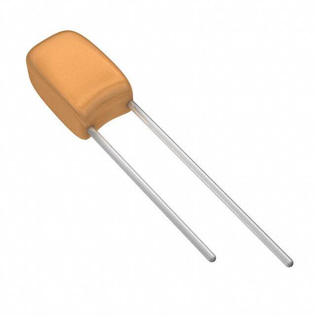
| 描述 | CAP TANT 10UF 21V 10% 2917钽质电容器-固体SMD 10uF 21volts 10% E cs Mld, 200 C Temp |
| ESR | 1 Ohms |
| ESR(等效串联电阻) | 1 欧姆 |
| 产品分类 | |
| 品牌 | Vishay SpragueVishay / Sprague |
| 产品手册 | |
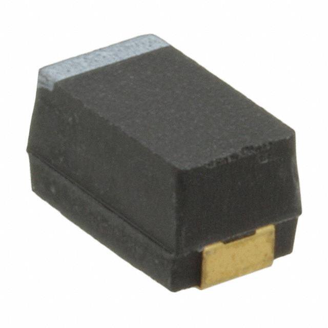
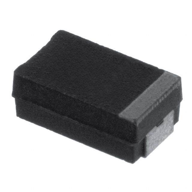
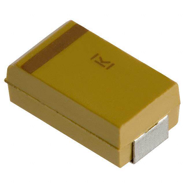
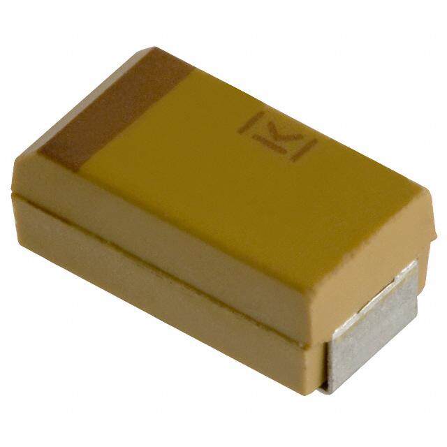
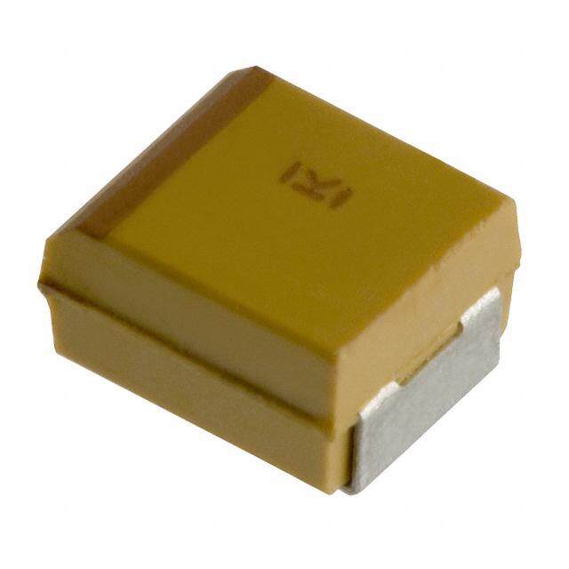
| 产品图片 |
|
| rohs | 符合RoHS无铅 / 符合限制有害物质指令(RoHS)规范要求 |
| 产品系列 | 钽电容器,钽质电容器-固体SMD,Vishay / Sprague TH5E106K021A1000TANTAMOUNT® TH5 |
| 数据手册 | |
| 产品型号 | TH5E106K021A1000TH5E106K021A1000 |
| 不同温度时的使用寿命 | - |
| 产品 | Tantalum Solid High Temperature |
| 产品种类 | 钽质电容器-固体SMD |
| 其它名称 | 718-1898-6 |
| 制造商尺寸代码 | E |
| 制造商库存号 | E Case |
| 包装 | Digi-Reel® |
| 单位重量 | 670 mg |
| 商标 | Vishay / Sprague |
| 商标名 | TANTAMOUNT |
| 外壳代码-in | 2917 |
| 外壳代码-mm | 7343 |
| 外壳宽度 | 4.3 mm |
| 外壳长度 | 7.3 mm |
| 大小/尺寸 | 0.287" 长 x 0.170" 宽(7.29mm x 4.32mm) |
| 安装类型 | 表面贴装 |
| 容差 | ±10%10 % |
| 封装 | Reel |
| 封装/外壳 | 2917(7343 公制) |
| 封装/箱体 | 2917 (7343 metric) |
| 工作温度 | -55°C ~ 200°C |
| 工作温度范围 | - 55 C to + 200 C |
| 引线间距 | - |
| 损耗因数DF | 6 |
| 标准包装 | 1 |
| 特性 | 高可靠性 |
| 电压-额定 | 21V |
| 电压额定值 | 21 V |
| 电容 | 10µF10 uF |
| 端接类型 | SMD/SMT |
| 类型 | 模制 |
| 系列 | TH5 |
| 高度 | 3.1 mm |
| 高度-安装(最大值) | 0.169"(4.30mm) |


PDF Datasheet 数据手册内容提取
TH5 www.vishay.com Vishay Sprague Solid Tantalum Surface Mount Chip Capacitors TANTAMOUNT™, Molded Case, HI-TMP®, Very High Temperature 200 °C FEATURES • Operating temperature up to +200 °C • Category voltage at +200 °C: same as rated voltage (RV) at 25 °C to 85 °C • 500 h continuous operation at RV • Gold plated terminations • 100 % surge current tested • Standard EIA 535BAAC case sizes • Moisture sensitivity level 1 • Material categorization: for definitions of compliance please see www.vishay.com/doc?99912 APPLICATIONS PERFORMANCE / ELECTRICAL CHARACTERISTICS • Oil and petroleum Operating Temperature: -55 °C to +200 °C • High temperature sensing and drilling systems Capacitance Range: 4.7 μF to 100 μF • Industrial Capacitance Tolerance: ± 10 %, ± 20 % • Safety critical industrial tools and products Voltage Range: 5 V to 24 V • High temperature extended activities DC DC • High temperature engines • Electronic sensors ORDERING INFORMATION TH5 E 106 K 021 B 1000 TYPE CASE CAPACITANCE CAPACITANCE CATEGORY VOLTAGE TERMINATION / ESR CODE TOLERANCE AT -55 °C TO +200 °C PACKAGING See Ratings This is expressed K = ± 10 % This is expressed Gold Maximum and Case in picofarads. M = ± 20 % in V. To complete the A = 7" (178 mm) reel 100 kHz ESR Codes table The first two three-digit block, B = 13" (330 mm) reel 0500 = 500 m digits are the zeros precede the G = 7" (178 mm) ½ reel 5000 = 5 significant voltage rating. Q = 7" (178 mm) partial reel 10R0 = 10.0 figures. The third Other (1) is the number of zeros to follow. Note (1) Other termination on request DIMENSIONS in inches [millimeters] L W T W H TH Glue Pad (MIN.) Glue Pad P CASE CODE EIA SIZE L W H P T T (MIN.) W H 0.287 ± 0.012 0.169 ± 0.012 0.110 ± 0.012 0.051 ± 0.012 0.094 ± 0.004 0.039 D 7343-31 [7.3 ± 0.30] [4.3 ± 0.30] [2.8 ± 0.30] [1.3 ± 0.30] [2.4 ± 0.10] [1.0] 0.287 ± 0.012 0.170 ± 0.012 0.158 ± 0.012 0.051 ± 0.012 0.095 ± 0.004 0.039 E 7343-43 [7.3 ± 0.30] [4.3 ± 0.30] [4.0 ± 0.30] [1.3 ± 0.30] [2.4 ± 0.10] [1.0] Note • Glue pad (non-conductive, part of molded case) is dedicated for glue attachment (as user option). Note • TH5 series capacitors have been designed for, and tested at category voltage at +200 °C for 500 h. As with all Tantalum capacitors, reliability and life time may be extended by application of lower voltage. Revision: 28-Sep-16 1 Document Number: 40146 For technical questions, contact: tantalum@vishay.com THIS DOCUMENT IS SUBJECT TO CHANGE WITHOUT NOTICE. THE PRODUCTS DESCRIBED HEREIN AND THIS DOCUMENT ARE SUBJECT TO SPECIFIC DISCLAIMERS, SET FORTH AT www.vishay.com/doc?91000
TH5 www.vishay.com Vishay Sprague RATINGS AND CASE CODES μF 5 V 8 V 21 V 24 V 4.7 E (2.50) 10 E (1.00, 0.50) 22 D (0.50), E (0.50) 100 E (0.25) Note • ESR limit (in ) is shown in parenthesis. CONSTRUCTION AND MARKING Gold Termination Capacitance Voltage Epoxy Silver encapsulation adhesive Polarity bar 10u21 Date code B1 2 Vishay marking Anode polarity bar TH5 Standard Marking Case Sizes “D” and “E” Marking: MnO / carbon / silver2 coating Capacitor marking includes an anode (+) polarity band, Solderable Leadframe Solderable anode capacitance in microfarads and the voltage rating. cathode Sintered termination The Vishay identification is included if space permits. A termination tantalum manufacturing date code is marked on all capacitors. Call the factory for further explanation. STANDARD RATINGS MAX. ESR MAX. DCL TYPICAL DCL MAX. DF MAX. RIPPLE CAPACITANCE CASE AT +25 °C PART NUMBER AT +25 °C AT +200 °C AT +25 °C 100 kHz (μF) CODE 100 kHz (μA) (μA) (%) I (A) () RMS 5 V AT +200 °C DC 100 E TH5E107(1)005(2)0250 5.0 300 8 0.250 0.81 8 V AT +200 °C DC 22 D TH5D226(1)008(2)0500 6.0 360 6 0.500 0.55 22 E TH5E226(1)008(2)0500 6.0 360 6 0.500 0.57 21 V AT +200 °C DC 10 E TH5E106(1)021(2)1000 2.1 120 6 1.000 0.41 10 E TH5E106(1)021(2)0500 2.1 120 6 0.500 0.57 24 V AT +200 °C DC 4.7 E TH5E475(1)024(2)2500 1.1 60 10 2.500 0.26 Note • Part number definitions: (1) Capacitance tolerance codes: K, M (2) Terminations and packaging: A, B, G, Q STANDARD PACKAGING QUANTITY UNITS PER REEL CASE CODE 13" FULL REEL 7" FULL REEL 7" HALF REEL 7" PARTIAL REEL D 2500 500 250 100 E 1500 400 200 100 Note • TH5 series capacitors have been designed for, and tested at category voltage at +200 °C for 500 h. As with all Tantalum capacitors, reliability and life time may be extended by application of lower voltage. Revision: 28-Sep-16 2 Document Number: 40146 For technical questions, contact: tantalum@vishay.com THIS DOCUMENT IS SUBJECT TO CHANGE WITHOUT NOTICE. THE PRODUCTS DESCRIBED HEREIN AND THIS DOCUMENT ARE SUBJECT TO SPECIFIC DISCLAIMERS, SET FORTH AT www.vishay.com/doc?91000
Molded Guide www.vishay.com Vishay Sprague Guide for Molded Tantalum Capacitors INTRODUCTION Rating for rating, tantalum capacitors tend to have as much as three times better capacitance / volume efficiency than Tantalum electrolytic capacitors are the preferred choice in aluminum electrolytic capacitors. An approximation of the applications where volumetric efficiency, stable electrical capacitance / volume efficiency of other types of capacitors parameters, high reliability, and long service life are primary may be inferred from the following table, which shows the considerations. The stability and resistance to elevated dielectric constant ranges of the various materials used in temperatures of the tantalum / tantalum oxide / manganese each type. Note that tantalum pentoxide has a dielectric dioxide system make solid tantalum capacitors an constant of 26, some three times greater than that of appropriate choice for today's surface mount assembly aluminum oxide. This, in addition to the fact that extremely technology. thin films can be deposited during the electrolytic process Vishay Sprague has been a pioneer and leader in this field, mentioned earlier, makes the tantalum capacitor extremely producing a large variety of tantalum capacitor types for efficient with respect to the number of microfarads available consumer, industrial, automotive, military, and aerospace per unit volume. The capacitance of any capacitor is electronic applications. determined by the surface area of the two conducting Tantalum is not found in its pure state. Rather, it is plates, the distance between the plates, and the dielectric commonly found in a number of oxide minerals, often in constant of the insulating material between the plates. combination with Columbium ore. This combination is known as “tantalite” when its contents are more than COMPARISON OF CAPACITOR one-half tantalum. Important sources of tantalite include DIELECTRIC CONSTANTS Australia, Brazil, Canada, China, and several African countries. Synthetic tantalite concentrates produced from e DIELECTRIC tin slags in Thailand, Malaysia, and Brazil are also a DIELECTRIC CONSTANT significant raw material for tantalum production. Air or vacuum 1.0 Electronic applications, and particularly capacitors, Paper 2.0 to 6.0 consume the largest share of world tantalum production. Plastic 2.1 to 6.0 Other important applications for tantalum include cutting Mineral oil 2.2 to 2.3 tools (tantalum carbide), high temperature super alloys, Silicone oil 2.7 to 2.8 chemical processing equipment, medical implants, and Quartz 3.8 to 4.4 military ordnance. Glass 4.8 to 8.0 Vishay Sprague is a major user of tantalum materials in the form of powder and wire for capacitor elements and rod and Porcelain 5.1 to 5.9 sheet for high temperature vacuum processing. Mica 5.4 to 8.7 Aluminum oxide 8.4 THE BASICS OF TANTALUM CAPACITORS Tantalum pentoxide 26 Most metals form crystalline oxides which are Ceramic 12 to 400K non-protecting, such as rust on iron or black oxide on copper. A few metals form dense, stable, tightly adhering, In the tantalum electrolytic capacitor, the distance between electrically insulating oxides. These are the so-called the plates is very small since it is only the thickness of the “valve”metals and include titanium, zirconium, niobium, tantalum pentoxide film. As the dielectric constant of the tantalum, hafnium, and aluminum. Only a few of these tantalum pentoxide is high, the capacitance of a tantalum permit the accurate control of oxide thickness by capacitor is high if the area of the plates is large: electrochemical means. Of these, the most valuable for the eA electronics industry are aluminum and tantalum. C = ------- t Capacitors are basic to all kinds of electrical equipment, from radios and television sets to missile controls and where automobile ignitions. Their function is to store an electrical charge for later use. C = capacitance Capacitors consist of two conducting surfaces, usually e = dielectric constant metal plates, whose function is to conduct electricity. They A = surface area of the dielectric are separated by an insulating material or dielectric. The dielectric used in all tantalum electrolytic capacitors is t = thickness of the dielectric tantalum pentoxide. Tantalum capacitors contain either liquid or solid Tantalum pentoxide compound possesses high-dielectric electrolytes. In solid electrolyte capacitors, a dry material strength and a high-dielectric constant. As capacitors are (manganese dioxide) forms the cathode plate. A tantalum being manufactured, a film of tantalum pentoxide is applied lead is embedded in or welded to the pellet, which is in turn to their electrodes by means of an electrolytic process. The connected to a termination or lead wire. The drawings show film is applied in various thicknesses and at various voltages the construction details of the surface mount types of and although transparent to begin with, it takes on different tantalum capacitors shown in this catalog. colors as light refracts through it. This coloring occurs on the tantalum electrodes of all types of tantalum capacitors. Revision: 13-Dec-2018 1 Document Number: 40074 For technical questions, contact: tantalum@vishay.com THIS DOCUMENT IS SUBJECT TO CHANGE WITHOUT NOTICE. THE PRODUCTS DESCRIBED HEREIN AND THIS DOCUMENT ARE SUBJECT TO SPECIFIC DISCLAIMERS, SET FORTH AT www.vishay.com/doc?91000
Molded Guide www.vishay.com Vishay Sprague SOLID ELECTROLYTE TANTALUM CAPACITORS TANTALUM CAPACITORS FOR ALL DESIGN CONSIDERATIONS Solid electrolyte capacitors contain manganese dioxide, which is formed on the tantalum pentoxide dielectric layer Solid electrolyte designs are the least expensive for a given by impregnating the pellet with a solution of manganous rating and are used in many applications where their very nitrate. The pellet is then heated in an oven, and the small size for a given unit of capacitance is of importance. manganous nitrate is converted to manganese dioxide. They will typically withstand up to about 10 % of the rated The pellet is next coated with graphite, followed by a layer DC working voltage in a reverse direction. Also important are their good low temperature performance characteristics of metallic silver, which provides a conductive surface between the pellet and the leadframe. and freedom from corrosive electrolytes. Vishay Sprague patented the original solid electrolyte Molded Chip tantalum capacitor encases the element in plastic resins, such as epoxy materials. After assembly, the capacitors and was the first to market them in 1956. Vishay capacitors are tested and inspected to assure long life and Sprague has the broadest line of tantalum capacitors and reliability. It offers excellent reliability and high stability for has continued its position of leadership in this field. Data sheets covering the various types and styles of Vishay consumer and commercial electronics with the added feature of low cost Sprague capacitors for consumer and entertainment electronics, industry, and military applications are available Surface mount designs of “Solid Tantalum” capacitors use where detailed performance characteristics must be lead frames or lead frameless designs as shown in the specified. accompanying drawings. MOLDED CHIP CAPACITOR Epoxy Silver Encapsulation Adhesive Anode Polarity Bar MnO/Carbon/ 2 Silver Coating Solderable Leadframe Solderable Anode Cathode Sintered Termination Termination Tantalum Revision: 13-Dec-2018 2 Document Number: 40074 For technical questions, contact: tantalum@vishay.com THIS DOCUMENT IS SUBJECT TO CHANGE WITHOUT NOTICE. THE PRODUCTS DESCRIBED HEREIN AND THIS DOCUMENT ARE SUBJECT TO SPECIFIC DISCLAIMERS, SET FORTH AT www.vishay.com/doc?91000
Molded Guide www.vishay.com Vishay Sprague COMMERCIAL PRODUCTS SOLID TANTALUM CAPACITORS - MOLDED CASE 793DX-CTC3- SERIES 293D 593D TR3 TP3 TL3 CTC4 PRODUCT IMAGE TYPE Surface mount TANTAMOUNT™, molded case Standard High performance, FEATURES CECC approved Low ESR Low ESR Very low DCL industrial grade automotive grade TEMPERATURE -55 °C to +125 °C RANGE CAPACITANCE 0.1 μF to 1000 μF 0.1 μF to 100 μF 1 μF to 470 μF 0.47 μF to 1000 μF 0.1 μF to 470 μF 0.1 μF to 470 μF RANGE VOLTAGE RANGE 4 V to 75 V 4 V to 50 V 4 V to 50 V 4 V to 75 V 4 V to 50 V 4 V to 50 V CAPACITANCE ± 10 %, ± 20 % TOLERANCE 0.005 CV or LEAKAGE 0.25 μA, 0.01 CV or 0.5 μA, whichever is greater CURRENT whichever is greater DISSIPATION 4 % to 30 % 4 % to 6 % 4 % to 15 % 4 % to 30 % 4 % to 15 % 4 % to 15 % FACTOR CASE CODES A, B, C, D, E A, B, C, D A, B, C, D, E A, B, C, D, E, W A, B, C, D, E A, B, C, D, E TERMINATION 100 % matte tin standard, tin / lead available SOLID TANTALUM CAPACITORS - MOLDED CASE SERIES TH3 TH4 TH5 PRODUCT IMAGE TYPE Surface mount TANTAMOUNT™, molded case High temperature +150 °C, High temperature +175 °C, FEATURES Very high temperature +200 °C automotive grade automotive grade TEMPERATURE -55 °C to +150 °C -55 °C to +175 °C -55 °C to +200 °C RANGE CAPACITANCE 0.33 μF to 220 μF 10 μF to 100 μF 4.7 μF to 100 μF RANGE VOLTAGE RANGE 6.3 V to 50 V 6.3 V to 35 V 5 V to 24 V CAPACITANCE ± 10 %, ± 20 % TOLERANCE LEAKAGE 0.01 CV or 0.5 μA, whichever is greater CURRENT DISSIPATION 4 % to 8 % 4.5 % to 8 % 6 % to 10 % FACTOR CASE CODES A, B, C, D, E B, C, D, E D, E 100 % matte tin standard, TERMINATION 100 % matte tin Gold plated tin / lead and gold plated available Revision: 13-Dec-2018 3 Document Number: 40074 For technical questions, contact: tantalum@vishay.com THIS DOCUMENT IS SUBJECT TO CHANGE WITHOUT NOTICE. THE PRODUCTS DESCRIBED HEREIN AND THIS DOCUMENT ARE SUBJECT TO SPECIFIC DISCLAIMERS, SET FORTH AT www.vishay.com/doc?91000
Molded Guide www.vishay.com Vishay Sprague HIGH RELIABILITY PRODUCTS SOLID TANTALUM CAPACITORS - MOLDED CASE SERIES TM3 T83 CWR11 95158 PRODUCT IMAGE TANTAMOUNT™, TANTAMOUNT™, TANTAMOUNT™, molded case, TYPE molded case, molded case, hi-rel. DLA approved hi-rel. COTS High reliability, High reliability, FEATURES MIL-PRF-55365/8 qualified Low ESR for medical Instruments standard and low ESR TEMPERATURE -55 °C to +125 °C RANGE CAPACITANCE 1 μF to 220 μF 0.1 μF to 470 μF 0.1 μF to 100 μF 4.7 μF to 220 μF RANGE VOLTAGE RANGE 4 V to 20 V 4 V to 63 V 4 V to 50 V CAPACITANCE ± 10 %, ± 20 % ± 5 %, ± 10 %, ± 20 % ± 10 %, ± 20 % TOLERANCE LEAKAGE 0.005 CV or 0.25 μA, 0.01 CV or 0.5 μA, whichever is greater CURRENT whichever is greater DISSIPATION 4 % to 8 % 4 % to 15 % 4 % to 6 % 4 % to 12 % FACTOR CASE CODES A, B, C, D, E A, B, C, D, E A, B, C, D C, D, E 100 % matte tin; 100 % matte tin; Tin / lead; Tin / lead solder plated; TERMINATION tin / lead; tin / lead tin / lead solder fused gold plated tin / lead solder fused Revision: 13-Dec-2018 4 Document Number: 40074 For technical questions, contact: tantalum@vishay.com THIS DOCUMENT IS SUBJECT TO CHANGE WITHOUT NOTICE. THE PRODUCTS DESCRIBED HEREIN AND THIS DOCUMENT ARE SUBJECT TO SPECIFIC DISCLAIMERS, SET FORTH AT www.vishay.com/doc?91000
Molded Guide www.vishay.com Vishay Sprague PLASTIC TAPE AND REEL PACKAGING in inches [millimeters] 0.157 ± 0.004 [4.0 ± 0.10] 10 pitches cumulative Tape thickness tolerance on tape Deformation 0.059 + 0.004 - 0.0 ± 0.008 [0.200] 0.014 between [1.5 + 0.10 - 0.0] [ 0M.3A5X]. embossments 0[2..007 ±9 ±0. 005.0]02 Embossment 0[1..07659 ± ± 0 0.1.000]4 Top cover tape A0 0.030 [0.75] 20° (BN1o MteA 6X). K0 B MIN . (Note 3) F W Mcoamxipmounment Top 0 0.030 [0.75] rotation cover MIN . (Note 4) (Side or front sectional view) tape 0.004 [0.1] Center lines P For tape feeder MAX. of cavity 1 D MIN. for components reference only 0.1079 x 0.047 [2.0 x 1.2] and larger. including draft. USER DIRECTION OF FEED Maximum (Note 5) Concentric around B0 cavity size (Note 5) (Note 1) Cathode (-) Anode (+) Direction of Feed 3.937 [100.0] Tape and Reel Specifications: all case sizes are available 20° maximum 0.039 [1.0] on plastic embossed tape per EIA-481. Standard reel component rotation MAX. diameter is 7" [178 mm], 13" [330 mm] reels are available and Typical component Tape recommended as the most cost effective packaging method. B0 ccaevnitteyr line 0.039 [1.0] The most efficient packaging quantities are full reel MAX. increments on a given reel diameter. The quantities shown 0.9843 [250.0] Typical allow for the sealed empty pockets required to be in component Camber conformance with EIA-481. Reel size and packaging A0 center line Allow a b l e c a m b e(tro tpo vbieew 0).039/3.937 [1/100] orientation must be specified in the Vishay Sprague part (Top view) non-cumulative over 9.843 [250.0] number. Notes • Metric dimensions will govern. Dimensions in inches are rounded and for reference only. (1) A , B , K , are determined by the maximum dimensions to the ends of the terminals extending from the component body and / or the body 0 0 0 dimensions of the component. The clearance between the ends of the terminals or body of the component to the sides and depth of the cavity (A , B , K ) must be within 0.002" (0.05 mm) minimum and 0.020" (0.50 mm) maximum. The clearance allowed must also prevent 0 0 0 rotation of the component within the cavity of not more than 20°. (2) Tape with components shall pass around radius “R” without damage. The minimum trailer length may require additional length to provide “R” minimum for 12 mm embossed tape for reels with hub diameters approaching N minimum. (3) This dimension is the flat area from the edge of the sprocket hole to either outward deformation of the carrier tape between the embossed cavities or to the edge of the cavity whichever is less. (4) This dimension is the flat area from the edge of the carrier tape opposite the sprocket holes to either the outward deformation of the carrier tape between the embossed cavity or to the edge of the cavity whichever is less. (5) The embossed hole location shall be measured from the sprocket hole controlling the location of the embossement. Dimensions of embossement location shall be applied independent of each other. (6) B dimension is a reference dimension tape feeder clearance only. 1 CASE TAPE B D K 1 1 F 0 P W CODE SIZE (MAX.) (MIN.) (MAX.) 1 MOLDED CHIP CAPACITORS; ALL TYPES A 0.165 0.039 0.138 ± 0.002 0.094 0.157 ± 0.004 0.315 ± 0.012 8 mm B [4.2] [1.0] [3.5 ± 0.05] [2.4] [4.0 ± 1.0] [8.0 ± 0.30] C D 0.32 0.059 0.217 ± 0.00 0.177 0.315 ± 0.004 0.472 ± 0.012 12 mm E [8.2] [1.5] [5.5 ± 0.05] [4.5] [8.0 ± 1.0] [12.0 ± 0.30] W Revision: 13-Dec-2018 5 Document Number: 40074 For technical questions, contact: tantalum@vishay.com THIS DOCUMENT IS SUBJECT TO CHANGE WITHOUT NOTICE. THE PRODUCTS DESCRIBED HEREIN AND THIS DOCUMENT ARE SUBJECT TO SPECIFIC DISCLAIMERS, SET FORTH AT www.vishay.com/doc?91000
Molded Guide www.vishay.com Vishay Sprague RECOMMENDED REFLOW PROFILES Capacitors should withstand reflow profile as per J-STD-020 standard, three cycles. T p T - 5 °C Max. ramp-up rate = 3 °C/s tp C Max. ramp-down rate = 6 °C/s C) T RE (° L Ts max. Preheat area tL U T A R T E s min. P M TE ts 25 Time 25 °C to peak TIME (s) PROFILE FEATURE SnPb EUTECTIC ASSEMBLY LEAD (Pb)-FREE ASSEMBLY Preheat / soak Temperature min. (T ) 100 °C 150 °C s min. Temperature max. (T ) 150 °C 200 °C s max. Time (t) from (T to T ) 60 s to 120 s 60 s to 120 s s smin. s max. Ramp-up Ramp-up rate (T to T ) 3 °C/s max. 3 °C/s max. L p Liquidus temperature (T ) 183 °C 217 °C L Time (t ) maintained above T 60 s to 150 s 60 s to 150 s L L Peak package body temperature (T ) Depends on case size - see table below p Time (tp) within 5 °C of the specified 20 s 30 s classification temperature (T ) C Time 25 °C to peak temperature 6 min max. 8 min max. Ramp-down Ramp-down rate (T to T ) 6 °C/s max. 6 °C/s max. p L PEAK PACKAGE BODY TEMPERATURE (T ) p PEAK PACKAGE BODY TEMPERATURE (T ) CASE CODE p SnPb EUTECTIC PROCESS LEAD (Pb)-FREE PROCESS A, B, C 235 °C 260 °C D, E, W 220 °C 250 °C PAD DIMENSIONS in inches [millimeters] D B C A A B C D CASE CODE (MIN.) (NOM.) (NOM.) (NOM.) MOLDED CHIP CAPACITORS, ALL TYPES A 0.071 [1.80] 0.067 [1.70] 0.053 [1.35] 0.187 [4.75] B 0.118 [3.00] 0.071 [1.80] 0.065 [1.65] 0.207 [5.25] C 0.118 [3.00] 0.094 [2.40] 0.118 [3.00] 0.307 [7.80] D 0.157 [4.00] 0.098 [2.50] 0.150 [3.80] 0.346 [8.80] E 0.157 [4.00] 0.098 [2.50] 0.150 [3.80] 0.346 [8.80] W 0.185 [4.70] 0.098 [2.50] 0.150 [3.80] 0.346 [8.80] Revision: 13-Dec-2018 6 Document Number: 40074 For technical questions, contact: tantalum@vishay.com THIS DOCUMENT IS SUBJECT TO CHANGE WITHOUT NOTICE. THE PRODUCTS DESCRIBED HEREIN AND THIS DOCUMENT ARE SUBJECT TO SPECIFIC DISCLAIMERS, SET FORTH AT www.vishay.com/doc?91000
Molded Guide www.vishay.com Vishay Sprague GUIDE TO APPLICATION 1. AC Ripple Current: the maximum allowable ripple be established when calculating permissible current shall be determined from the formula: operating levels. (Power dissipation calculated using +25 °C temperature rise). P I = ------------ RMS R 6. Printed Circuit Board Materials: molded capacitors ESR are compatible with commonly used printed circuit where, board materials (alumina substrates, FR4, FR5, G10, PTFE-fluorocarbon and porcelanized steel). P = power dissipation in W at +25 °C as given in the tables in the product datasheets (Power 7. Attachment: Dissipation). 7.1 Solder Paste: the recommended thickness of the R = the capacitor equivalent series resistance at ESR solder paste after application is 0.007" ± 0.001" the specified frequency [0.178 mm ± 0.025 mm]. Care should be exercised in selecting the solder paste. The metal purity should be 2. AC Ripple Voltage: the maximum allowable ripple as high as practical. The flux (in the paste) must be voltage shall be determined from the formula: active enough to remove the oxides formed on the V = I x Z metallization prior to the exposure to soldering heat. In RMS RMS practice this can be aided by extending the solder or, from the formula: preheat time at temperatures below the liquidous state of the solder. P V = Z ------------ RMS R 7.2 Soldering: capacitors can be attached by ESR conventional soldering techniques; vapor phase, where, convection reflow, infrared reflow, wave soldering, and hot plate methods. The soldering profile charts P = power dissipation in W at +25 °C as given in show recommended time / temperature conditions the tables in the product datasheets (Power for soldering. Preheating is recommended. The Dissipation). recommended maximum ramp rate is 2 °C per s. R = the capacitor equivalent series resistance at Attachment with a soldering iron is not ESR the specified frequency recommended due to the difficulty of controlling temperature and time at temperature. The soldering Z = the capacitor impedance at the specified iron must never come in contact with the capacitor. frequency 2.1 The sum of the peak AC voltage plus the applied DC 7.2.1 Backward and Forward Compatibility: capacitors voltage shall not exceed the DC voltage rating of the with SnPb or 100 % tin termination finishes can be capacitor. soldered using SnPb or lead (Pb)-free soldering processes. 2.2 The sum of the negative peak AC voltage plus the applied DC voltage shall not allow a voltage reversal 8. Cleaning (Flux Removal) After Soldering: molded exceeding 10 % of the DC working voltage at capacitors are compatible with all commonly used +25 °C. solvents such as TES, TMS, Prelete, Chlorethane, Terpene and aqueous cleaning media. However, 3. Reverse Voltage: solid tantalum capacitors are not CFC / ODS products are not used in the production intended for use with reverse voltage applied. of these devices and are not recommended. However, they have been shown to be capable of Solvents containing methylene chloride or other withstanding momentary reverse voltage peaks of up epoxy solvents should be avoided since these will to 10 % of the DC rating at 25 °C and 5 % of the DC attack the epoxy encapsulation material. rating at +85 °C. 8.1 When using ultrasonic cleaning, the board may 4. Temperature Derating: if these capacitors are to be resonate if the output power is too high. This operated at temperatures above +25 °C, the vibration can cause cracking or a decrease in the permissible RMS ripple current shall be calculated adherence of the termination. DO NOT EXCEED 9W/l using the derating factors as shown: at 40 kHz for 2 min. 9. Recommended Mounting Pad Geometries: proper TEMPERATURE (°C) DERATING FACTOR mounting pad geometries are essential for +25 1.0 successful solder connections. These dimensions +85 0.9 are highly process sensitive and should be designed +125 0.4 to minimize component rework due to unacceptable +150 (1) 0.3 solder joints. The dimensional configurations shown +175 (1) 0.2 are the recommended pad geometries for both wave +200 (1) 0.1 and reflow soldering techniques. These dimensions are intended to be a starting point for circuit board Note designers and may be fine tuned if necessary based (1)Applicable for dedicated high temperature product series upon the peculiarities of the soldering process and / or circuit board design. 5. Power Dissipation: power dissipation will be affected by the heat sinking capability of the mounting surface. Non-sinusoidal ripple current may produce heating effects which differ from those shown. It is important that the equivalent I value RMS Revision: 13-Dec-2018 7 Document Number: 40074 For technical questions, contact: tantalum@vishay.com THIS DOCUMENT IS SUBJECT TO CHANGE WITHOUT NOTICE. THE PRODUCTS DESCRIBED HEREIN AND THIS DOCUMENT ARE SUBJECT TO SPECIFIC DISCLAIMERS, SET FORTH AT www.vishay.com/doc?91000
Typical Performance Characteristics www.vishay.com Vishay Sprague TH5 Tantalum Capacitors ELECTRICAL PERFORMANCE CHARACTERISTICS ITEM PERFORMANCE CHARACTERISTICS Category temperature range -55 °C to +200 °C Category voltage Category voltage is the same within entire temperature range and is equal to rated voltage Capacitance tolerance ± 20 %, ± 10 %, tested via bridge method, at 25 °C, 120 Hz Dissipation factor Limits per Standard Ratings table. Tested via bridge method, at 25 °C, 120 Hz ESR Limits per Standard Ratings table. Tested via bridge method, at 25 °C, 100 kHz Leakage current After application of rated voltage applied to capacitors for 5 min using a steady source of power with 1 kΩ resistor in series with the capacitor under test, leakage current at 25 °C is not more than described in Standard Ratings table. Note that the leakage current varies with temperature and applied voltage. ENVIRONMENTAL PERFORMANCE CHARACTERISTICS ITEM CONDITION POST TEST PERFORMANCE Life test 500 h application of rated voltage at 200 °C Capacitance change -30 % / +10 % of initially specified value Dissipation factor Not to exceed 150 % of initial ESR Not to exceed 125 % of initial Leakage current Not to exceed 1 mA (at 200 °C) Moisture Cycled, 20 cycles, MIL-STD-202, method 106 Capacitance change ± 15 % of initially specified value resistance Dissipation factor Not to exceed 150 % of initial Leakage current Not to exceed 200 % of initial Surge voltage 85 °C, 1000 cycles at 1.3 rated voltage in series Capacitance change ± 5 % of initially specified value with 33 Ω resistor, MIL-PRF-55365 Dissipation factor Initial specified value or less Leakage current Initial specified value or less Note • All measurements to be performed after 24 h conditioning at room temperature MECHANICAL PERFORMANCE CHARACTERISTICS ITEM CONDITION POST TEST PERFORMANCE Terminal strength / Apply a pressure load of 17.7 N for 60 s Capacitance change Within ± 10 % of initial value Shear force test horizontally to the center of capacitor side body. Dissipation factor Initial specified limit Leakage current Initial specified limit There shall be no mechanical or visual damage to capacitors post-conditioning. Vibration MIL-STD-202, method 204, condition D, There shall be no mechanical or visual damage and the 10 Hz to 2000 Hz, 20 g peak components shall meet the original electrical requirements Resistance MIL-STD-202, method 210, condition K Capacitance change ± 5 % of initially specified value to solder heat Dissipation factor Initial specified value or less Leakage current Initial specified value or less There shall be no mechanical or visual damage to capacitors post-conditioning. Solderability MIL-STD-202, method 208, All terminations shall exhibit a continuous solder coating free from ANSI / J-STD-002, test B defects for a minimum of 95 % of the critical area of any individual Applies only to solder and tin plated terminations. termination Does not apply to gold terminations. Resistance MIL-STD-202, method 215 Marking has to remain legible, no degradation of encapsulation to solvents material Flammability Encapsulation materials meet UL 94 V-0 with an oxygen index of 32 % Note • All measurements to be performed after 24 h conditioning at room temperature Revision: 19-Jul-17 1 Document Number: 40206 For technical questions, contact: tantalum@vishay.com THIS DOCUMENT IS SUBJECT TO CHANGE WITHOUT NOTICE. THE PRODUCTS DESCRIBED HEREIN AND THIS DOCUMENT ARE SUBJECT TO SPECIFIC DISCLAIMERS, SET FORTH AT www.vishay.com/doc?91000
Legal Disclaimer Notice www.vishay.com Vishay Disclaimer ALL PRODUCT, PRODUCT SPECIFICATIONS AND DATA ARE SUBJECT TO CHANGE WITHOUT NOTICE TO IMPROVE RELIABILITY, FUNCTION OR DESIGN OR OTHERWISE. Vishay Intertechnology, Inc., its affiliates, agents, and employees, and all persons acting on its or their behalf (collectively, “Vishay”), disclaim any and all liability for any errors, inaccuracies or incompleteness contained in any datasheet or in any other disclosure relating to any product. Vishay makes no warranty, representation or guarantee regarding the suitability of the products for any particular purpose or the continuing production of any product. To the maximum extent permitted by applicable law, Vishay disclaims (i) any and all liability arising out of the application or use of any product, (ii) any and all liability, including without limitation special, consequential or incidental damages, and (iii) any and all implied warranties, including warranties of fitness for particular purpose, non-infringement and merchantability. Statements regarding the suitability of products for certain types of applications are based on Vishay’s knowledge of typical requirements that are often placed on Vishay products in generic applications. Such statements are not binding statements about the suitability of products for a particular application. It is the customer’s responsibility to validate that a particular product with the properties described in the product specification is suitable for use in a particular application. Parameters provided in datasheets and / or specifications may vary in different applications and performance may vary over time. All operating parameters, including typical parameters, must be validated for each customer application by the customer’s technical experts. Product specifications do not expand or otherwise modify Vishay’s terms and conditions of purchase, including but not limited to the warranty expressed therein. Except as expressly indicated in writing, Vishay products are not designed for use in medical, life-saving, or life-sustaining applications or for any other application in which the failure of the Vishay product could result in personal injury or death. Customers using or selling Vishay products not expressly indicated for use in such applications do so at their own risk. Please contact authorized Vishay personnel to obtain written terms and conditions regarding products designed for such applications. No license, express or implied, by estoppel or otherwise, to any intellectual property rights is granted by this document or by any conduct of Vishay. Product names and markings noted herein may be trademarks of their respective owners. © 2017 VISHAY INTERTECHNOLOGY, INC. ALL RIGHTS RESERVED Revision: 08-Feb-17 1 Document Number: 91000