ICGOO在线商城 > TCFGP0J156M8R
 Datasheet下载
- 型号: TCFGP0J156M8R
- 制造商: ROHM Semiconductor
- 库位|库存: xxxx|xxxx
- 要求:
| 数量阶梯 | 香港交货 | 国内含税 |
| +xxxx | $xxxx | ¥xxxx |
查看当月历史价格
查看今年历史价格
TCFGP0J156M8R产品简介:
ICGOO电子元器件商城为您提供TCFGP0J156M8R由ROHM Semiconductor设计生产,在icgoo商城现货销售,并且可以通过原厂、代理商等渠道进行代购。 提供TCFGP0J156M8R价格参考¥1.32-¥1.32以及ROHM SemiconductorTCFGP0J156M8R封装/规格参数等产品信息。 你可以下载TCFGP0J156M8R参考资料、Datasheet数据手册功能说明书, 资料中有TCFGP0J156M8R详细功能的应用电路图电压和使用方法及教程。
| 参数 | 数值 |
| 产品目录 | |
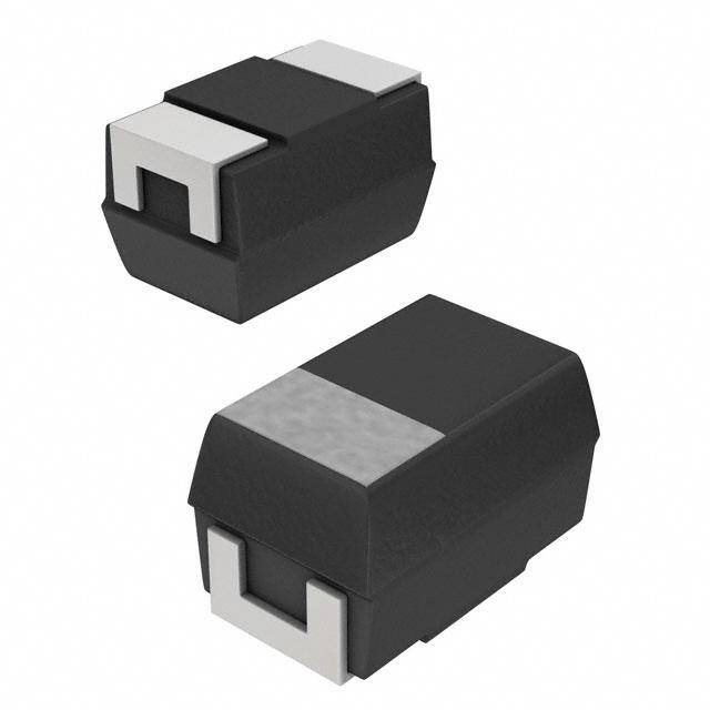
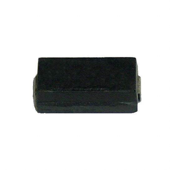
| 描述 | CAP TANT 15UF 6.3V 20% 0805 |
| ESR(等效串联电阻) | 7.7 欧姆 |
| 产品分类 | |
| 品牌 | Rohm Semiconductor |
| 数据手册 | http://www.rohm.com/web/global/search/parametric/-/search/generateQRCode/dsheet/22/1/40203010/TCFGP1A105M8R |
| 产品图片 |
|
| 产品型号 | TCFGP0J156M8R |
| rohs | 无铅 / 符合限制有害物质指令(RoHS)规范要求 |
| 产品系列 | TCFG |
| 不同温度时的使用寿命 | - |
| 产品培训模块 | http://www.digikey.cn/PTM/IndividualPTM.page?site=cn&lang=zhs&ptm=9056 |
| 产品目录绘图 |
|
| 产品目录页面 | |
| 其它名称 | 511-1489-2 |
| 制造商尺寸代码 | P |
| 包装 | 带卷 (TR) |
| 大小/尺寸 | 0.079" 长 x 0.049" 宽(2.00mm x 1.25mm) |
| 安装类型 | 表面贴装 |
| 容差 | ±20% |
| 封装/外壳 | 0805(2012 公制) |
| 工作温度 | -55°C ~ 125°C |
| 引线间距 | - |
| 标准包装 | 2,000 |
| 特性 | 内置式保险丝安全保护功能 |
| 电压-额定 | 6.3V |
| 电容 | 15µF |
| 类型 | 模制 |
| 高度-安装(最大值) | 0.047"(1.20mm) |
-2012-pkg.jpg)


- 商务部:美国ITC正式对集成电路等产品启动337调查
- 曝三星4nm工艺存在良率问题 高通将骁龙8 Gen1或转产台积电
- 太阳诱电将投资9.5亿元在常州建新厂生产MLCC 预计2023年完工
- 英特尔发布欧洲新工厂建设计划 深化IDM 2.0 战略
- 台积电先进制程称霸业界 有大客户加持明年业绩稳了
- 达到5530亿美元!SIA预计今年全球半导体销售额将创下新高
- 英特尔拟将自动驾驶子公司Mobileye上市 估值或超500亿美元
- 三星加码芯片和SET,合并消费电子和移动部门,撤换高东真等 CEO
- 三星电子宣布重大人事变动 还合并消费电子和移动部门
- 海关总署:前11个月进口集成电路产品价值2.52万亿元 增长14.8%


PDF Datasheet 数据手册内容提取
TCFG series P Case Tantalum capacitors Chip tantalum capacitors with open-function built-in TCFG series P Case (cid:122)Features (cid:122)External dimensions (Unit : mm) 1) Safety design by open function built - in. Anode mark 2) Wide capacitance range 3) Screening by thermal shock. L W1 H W2 S S + − Case code L W1 W2 H S P (2012) 2.0 +− 0.2 1.25 +− 0.2 0.9 +− 0.2 Max.1.20 0.45 +− 0.3 (cid:122)Product designation T C F G P 1 A 1 0 5 M 8 R 11 2 3 4 5 6 11 Series name 4 Capacitance TCFG Nominal capacitance in pF in 3 digits : 2significant figure representing the number of 0's. 2 Case code TCFG ····· P 5 Capacitance tolerance 3 Rated Voltage M :+− 20% K : +− 10% Rated voltage (V) 4 6.3 10 16 20 25 6 Taping CODE 0G 0J 1A 1C 1D 1E 8 : Tape width (8mm) R : Positive electrode on the side opposite to sprocket hole Rev.A 1/13
TCFG series P Case Tantalum capacitors (cid:122)Capacitance range TCFG series P Case Rated voltage (µF) 4 6.3 10 16 20 25 0G 0J 1A 1C 1D 1E 1.0 (105) P P P P 1.5 (155) P P P 2.2 (225) P P P P 3.3 (335) P P P P 4.7 (475) P P P 6.8 (685) P P 10 (106) P P 15 (156) P P 22 (226) P 33 (336) 47 (476) 68 (686) Remark) Case size codes (P) in the above show each size products line-up. (cid:122)Marking The indications listed below should be given on the surface of a capacitor. Polarity : The polarity should be shown by bar. (on the anode side) Rated DC voltage : Due to the small size of P case, a voltage code is used as shown below. Nominal capacitance Voltage Code Rated DC Voltage (V) Capacitance Code Nominal Capacitance (µF) g 4 A 1.0 j 6.3 E 1.5 A 10 J 2.2 C 16 N 3.3 D 20 S 4.7 E 25 W 6.8 a 10 e 15 j 22 Visual typical example (1) voltage code (2) capacitance code [P Case] note 1) j J − − (1) (2) j J − − A A note 2) voltage code and capacitance code are variable with parts number Rev.A 2/13
TCFG series P Case Tantalum capacitors (cid:122)Characteristics Test conditions Item Performance (based on JIS C5101-1 and JIS C5101-3) Operating Temperature −55 °C to +125 °C Voltage reduction when temperature exceeds +85°C Maximum operating temperature +85 °C with no voltage derating Rated Voltage (V.DC) 4 6.3 10 16 20 25 at 85°C Category Voltage (V.DC) 2.5 4 6.3 10 13 16 at 125°C Surge Voltage 5.2 8 13 20 26 32 at 85°C DC leakage current 0.5µA or 0.01CV whichever is greater As per 4.9 JIS C 5101-1 (Shown in "Standard list") As per 4.5.1 JIS C 5101-3 Voltage : Rated voltage for 1 min Capacitance tolerance Shall be satisfied allowance range. As per 4.7 JIS C 5101-1 ±10%, ±20% As per 4.5.2 JIS C 5101-3 Measuring frequency : 120±12Hz Measuring voltage : 0.5Vrms, +1.5V.DC Measuring circuit : DC Equivalent series circuit Tangent of loss angle Shall be satisfied the voltage on "Standard list" As per 4.8 JIS C 5101-1 (Df, tanδ) As per 4.5.3 JIS C 5101-3 Measuring frequency : 120±12Hz Measuring voltage : 0.5Vrms, +1.5V.DC Measuring circuit : DC Equivalent series circuit Impedance Shall be satisfied the voltage on "Standard list" As per 4.10 JIS C 5101-1 As per 4.5.4 JIS C 5101-3 Measuring frequency: 100±10kHz Measuring voltage : 0.5Vrms or less Measuring circuit : DC Equivalent series circuit Resistance to Appearance There should be no significant abnormality. As per 4.14 JIS C 5101-1 soldering heat The indications should be clear. As per 4.6 JIS C 5101-3 L.C Less than initial limit Dip in the solder bath Solder temp : 260±5°C ∆C / C Within ±10% of initial value Duration : 5±0.5s Repetition : 1 tanδ Less than 150% of initial limit Dip in the solder bath Fail-Safe open unit actuation Within 320°C − 20s Solder temp : 320±5°C Temperature Appearance There should be no significant abnormality. As per 4.16 JIS C 5101-1 cycle As per 4.10 JIS C 5101-3 L.C Less than initial limit Repetition : 5 cycles (1 cycle : steps 1 to 4) without discontinuation. ∆C / C 1 to 10µF : within ±10% of initial value 15 to 22µF : within ±20% of initial value Step Temp. Time tanδ Less than 150% of initial limit 1 −55 +− 3°C 30 +− 3min 2 Room temp. 3min. or less 3 125 +− 2°C 30 +− 3min 4 Room temp. 3min. or less Moisture Appearance There should be no significant abnormality. As per 4.22 JIS C 5101-1 resistance The indications should be clear. As per 4.12 JIS C 5101-3 L.C Less than initial limit After leaving the sample under such atmospheric condition that the temperature and humidity are ∆C / C Within ±20% of initial value 60±2°C and 90 to 95%RH, respectively, for tanδ Less than 150% of initial limit 500±12h level it at room temperature for 1 to 2h and then measure the sample. Rev.A 3/13
TCFG series P Case Tantalum capacitors Test conditions Item Performance (based on JIS C5101-1 and JIS C5101-3) Temperature Temp. −55°C As per 4.29 JIS C 5101-1 Stability As per 4.13 JIS C 5101-3 ∆C / C Within 0/−15%of initial value tanδ Shall be satisfied the voltage on "Standard list" L.C − Temp. +85°C ∆C / C Within +15/0%of initial value tanδ Shall be satisfied the voltage on "Standard list" L.C 5µA or 0.1CV whichever is greater Temp. +125°C ∆C / C Within +20/0%of initial value tanδ Shall be satisfied the voltage on "Standard list" L.C 6.3µA or 0.125CV whichever is greater Surge Appearance There should be no significant abnormality. As per 4.26 JIS C 5101-1 Voltage As per 4.14 JIS C 5101-3 L.C Shall be satisfied the voltage on "Standard list" Apply the specified surge voltage every 5±0.5min. ∆C / C Within ±10%of initial value for 30±5 s. each time in the atmospheric condition of 85±2°C. tanδ Less than 150% of initial limit Repeat this procedure 1,000 times. Loading at Appearance There should be no significant abnormality. As per 4.23 JIS C 5101-1 High As per 4.15 JIS C 5101-3 temperature L.C Less than initial limit After applying the rated voltage for 1000+36/0h ∆C / C Within ±10%of initial value without discontinuation via the serial resistance tanδ Less than 150% of initial limit of 3Ω or less at a temperature of 85±2°C, leave the sample at room temperature/humidity for 1 to 2h and measure the value. Terminal Capacitance The measured value should be stable. As per 4.35 JIS C 5101-1 Strength As per 4.9 JIS C 5101-3 Appearance There should be no significant abnormality. A force is applied to the terminal until it bends to 1mm and by a prescribed tool maintain the condition for 5s. (See the figure below.) (Unit : mm) 20 50 F (Apply force) R230 1 Thickness 1.6mm 45 45 Adhesiveness The terminal should not come off. As per 4.34 JIS C 5101-1 As per 4.8 JIS C 5101-3 Apply force of 5N in the two directions shown in the figure below for 10±1s after mounting the terminal on a circuit board. product C YA10 Apply force A5 a circuit board Rev.A 4/13
TCFG series P Case Tantalum capacitors Test conditions Item Performance (based on JIS C5101-1 and JIS C5101-3) Dimensions Be based on "External dimensions" Measure using a caliper of JIS B 7505 Class 2 or higher grade. Resistance to solvents The indication should be clear. As per 4.32 JIS C 5101-1 As per 4.18 JIS C 5101-3 Dip in the isopropyl alcohol for 30±5s, at room temperature. Solderability 3/4 or more surface area of the solder coated As per 4.15.2 JIS C 5101-1 terminal dipped in the soldering bath should be As per 4.7 JIS C 5101-3 covered with the new solder. Dip speed = 25±2.5mm/s Pre-treatment (accelerated aging) : Leave the sample on the boiling distilled water for 1h. Solder temp. : 235±5°C Duration : 2±0.5s Solder : H63A Flux : Rosin 25%, IPA 75% Vibration Capacitance Measure value should not fluctuate during the As per 4.17 JIS C 5101-1 measurement. Frequency : 10 to 55 to 10Hz/min. Appearance There should be no significant abnormality. Amplitude : 1.5mm Time : 2h each in X and Y directions Mounting : The terminal is soldered on a print circuit board. Rev.A 5/13
TCFG series P Case Tantalum capacitors (cid:122)Table 1 standard list, TCFG series P Case (P : 2012) VRoalttaegde DVeorltaatgeed VSoultraggee CapacitanceTolerance Lceuarkreangte DF1(%20)Hz Im1p0e0dkaHnzce Case Part No. @(8V5)°C @1(2V5)°C @(8V5)°C 1(2µ0FH)z (%) 1W2(m5V°A.C6)0s −55°C 2855°˚CC 125°C (Ω) code TCFG P 0G 225 4 2.5 5.2 2.2 ±20,±10 0.5 15 10 15 4.0 P TCFG P 0G 335 4 2.5 5.2 3.3 ±20,±10 0.5 30 20 30 17.5 P TCFG P 0G 475 4 2.5 5.2 4.7 ±20,±10 0.5 30 20 30 14.4 P TCFG P 0G 685 4 2.5 5.2 6.8 ±20,±10 0.5 30 20 30 11.8 P TCFG P 0G 106 4 2.5 5.2 10 ±20,±10 0.5 30 20 30 9.3 P TCFG P 0G 156 4 2.5 5.2 15 ±20,±10 0.6 30 20 30 8.3 P TCFG P 0G 226 4 2.5 5.2 22 ±20,±10 0.9 30 20 30 7.7 P TCFG P 0J 155 6.3 4 8 1.5 ±20,±10 0.5 15 10 15 17.5 P TCFG P 0J 225 6.3 4 8 2.2 ±20,±10 0.5 30 20 30 4.0 P TCFG P 0J 335 6.3 4 8 3.3 ±20,±10 0.5 30 20 30 14.4 P TCFG P 0J 475 6.3 4 8 4.7 ±20,±10 0.5 30 20 30 11.8 P TCFG P 0J 685 6.3 4 8 6.8 ±20,±10 0.5 30 20 30 9.3 P TCFG P 0J 106 6.3 4 8 10 ±20,±10 0.6 30 20 30 8.3 P TCFG P 0J 156 6.3 4 8 15 ±20,±10 0.9 30 20 30 7.7 P TCFG P 1A 105 10 6.3 13 1.0 ±20,±10 0.5 15 10 15 17.5 P TCFG P 1A 155 10 6.3 13 1.5 ±20,±10 0.5 30 20 30 16.1 P TCFG P 1A 225 10 6.3 13 2.2 ±20,±10 0.5 30 20 30 4.0 P TCFG P 1A 335 10 6.3 13 3.3 ±20,±10 0.5 30 20 30 11.8 P TCFG P 1A 475 10 6.3 13 4.7 ±20,±10 0.5 30 20 30 6.0 P TCFG P 1C 105 16 10 20 1.0 ±20,±10 0.5 15 10 15 16.5 P TCFG P 1D 105 20 13 26 1.0 ±20,±10 0.5 15 10 15 16.1 P TCFG P 1E 105 25 16 33 1.0 ±20,±10 0.5 15 10 15 16.1 P =Tolerance (M : ±20%, K : ±10%) (cid:122)Packaging specifications Case code A±0.1 B±0.1 t1±0.05 t2±0.1 P (2012) 1.55 2.3 0.25 1.5 Taping P Case 1 0. +−5 φ1.5 +− 0 .01 1.7 t1 A B +−3.5 0.05 +0 0.2− 8. 4.0 +− 0.21.0 +− 0.054.0 +− 0.1 Products t2 Pull out direction Rev.A 6/13
TCFG series P Case Tantalum capacitors (cid:122)Packaging style Case size Packaging Packaging style Symbol Basic ordering unit P Case Taping Plastic taping φ180mm reel R 2,000 Reel Plastic reel + 1.09.00 11.4 +− 1.0 2 0. +3 − 1 φ +φ 1600 φ0180−1.5 Label sticking position EIAJ ET - 7200B Rev.A 7/13
TCFG series P Case Tantalum capacitors (cid:122) Recommended condition of reflow soldering (1) Soldering Conditions (℃) ⑤Peak temperature 250 Reflow heating rate ③ 200 Temperature 150 100 ① ②Preliminary heating ④Soldering ⑥Cooling 50 Pre heating rate 0 Recommended condition of reflow soldering ①Pre heating rate : 1 to 5°C/ s ②Preliminary heating : 120 to 160°C, 50 to 120s ③Reflow heating rate : 1 to 5°C / s ④Soldering : 200°C, 30 to 60s ⑤Peak temperature : 230 to 260℃ 10s Max. ⑥Cooling : 60s Min. ⑦Time : 2times Max. Recommended condition of hand soldering ①Temperature (30W Max.) : 300°C Max. ②Time : 5s Max. Flow soldering (Dip • Wave soldering) 270 TCFG Series 260 C)250 E ( R240 U T A ER230 P M TE220 210 200 0 2 4 6 8 10 12 14 16 TIME (s) Fig.1 Rev.A 8/13
TCFG series P Case Tantalum capacitors (2) Leakage current-to-voltage ratio L C D 1 L / C D O TI A R T N RE 0.1 R U C E G A K A E L 0.01 0 20 40 60 80 100 % OF RATED VOLTAGE (VR) Fig.2 (3) Derating voltage as function of temperature 100 85°C 125°C )R Rated Voltage Surge Voltage Category Voltage Surge Voltage V 90 C1 ( (V.DC) (V.DC) (V.DC) (V.DC) D V R 80 4 5.0 2.5 3.4 C °85 6.3 8 4 5 T OF 70 10 13 6.3 9 N CE 16 20 10 12 R 60 E P 20 26 13 16 50 75 85 95 105 115 125 TEMPERATURE ( C) Fig.3 (4) Reliability The malfunction rate of tantalum solid state electrolytic capacitors varies considerably depending on the conditions of usage (ambient temperature, applied voltage, circuit resistance). Formula for calculating malfunction rate λp = λb × (πE × πSR × πQ × πCV) λp : Malfunction rate stemming from operation λb : Basic malfunction rate πE : Environmental factors πSR : Series resistance πQ : Level of malfunction rate πCV : Capacitance For details on how to calculate the malfunction rate stemming from operation, see the tantalum solid state electrolytic capacitors column in MIL-HDBK-217. Rev.A 9/13
TCFG series P Case Tantalum capacitors Malfunction rate as function of operating Malfunction rate as function of circuit resistance (Ω/V) temperature and rated voltage 1.0 6.0 Ratio =Applied Voltage Rated Voltage 1.0 CIENT 00..35 πNT () 4.0 RE RATE COEFFI00..0000..3612 00..75 ANCE COEFFICIE 012...800 AILU0.02 0.3 SIST 0.6 F E 0.01 R 0.4 0.1 20 40 60 85 0.1 0.2 0.4 0.6 1.0 2.0 3.0 OPERATING TEMPERATURE ( C) RESISTANCE OF CIRCUIT (Ω / V) Fig.4 Fig.5 (5) External temperature vs. fuse blowout (6) Power vs. fuse blowout characteristics / Product surface temperature 100 °AL TEMPERATURE (C)333333301234560000000 APBh fcccaaaaaliflsss efeeead i(((le323d205112628))) ERATING TIME (s) 456789000000 open-funcsctuuiorrfvnae ABPcc eoh ccc fat aaaetrhsssameeeecp tp(((e.332rro250isd121tiu682cc)))ts223050000 °)C( TCUDORP EHT FO .PM RN290 no failed OP 30 ET EXTE227800 1200 operating area 150 ECAFR U 260 0 S 1 10 100 0 1 2 3 4 5 6 7 8 9 10 no operating area OPERATING TIME (s) ELECTRIC POWER (W) Fig.6 Fig.7 Note: Solder the chip at 300°C or less. If it is soldered using a temperature higher than 300°C, open function built-in may operate. (7) Maximum power dissipation Warming of the capacitor due to ripple voltage balances with warming caused by Joule heating and by radiated heat. Maximum allowable warming of the capacitor is to 5°C above ambient temperature. When warming exceeds 5°C, it can damage the dielectric and cause a short circuit. Power dissipation (P) = I2・R Ripple current P : As shown in table at right R : Equivalent series resistance Notes: 1. Please be aware that when case size is changed, maximum allowable power dissipation is reduced. 2. Maximum power dissipation varies depending on the package. Be sure to use a case which will keep warming within the limits shown in the table below. Rev.A 10/13
TCFG series P Case Tantalum capacitors Allowable power dissipation (W) and maximum temperature rising Ambient Case temp +25°C +55°C +85°C +125°C P case (2012) 0.025 0.022 0.020 0.010 Max. Temp Rise (°C) 5 5 5 2 (8) Impedance frequency characteristics (9) ESR frequency characteristics 100000 100 A105 A105 P case (2012) 10000 P case (2012) G475 G475 A case (3216) A case (3216) C105 ΩNCE ()1100000 CACB 13cc03aa55ssee ((33251268)) ΩR () 10 ACB 3cc3aa5ssee ((33251268)) A S D E E MP 10 1 I 1 0.1 1 100 10k 1M 100M500M 1 100 10k 1M 100M500M FREQUENCY (Hz) FREQUENCY (Hz) Fig.8 Fig.9 (10) Temperature characteristics 10 CAP 120Hz 5 DF 120Hz 10V−1µF P case (2012) 10V−1µF P case (2012) 4V−4.7µF A case (3216) 4V−4.7µF A case (3216) 4V−33µF B case (3528) 4V−33µF B case (3528) 6 4 %) E ( 2 3 NG %) P CHA −20 DF ( 2 A C −6 1 −1−055 25 85 125 −055 25 85 125 TEMPERATURE (°C) TEMPERATURE (°C) Fig.10 Fig.11 LC 1WV IMPEDANCE 100kHz 1000 3 10V−1µF P case (2012) 10V−1µF P case (2012) 4V−4.7µF A case (3216) 4V−4.7µF A case (3216) 4V−33µF B case (3528) 4V−33µF B case (3528) 100 Ω) 2 A) CE ( n N C ( DA L E P 10 M 1 I −055 25 85 125 −055 25 85 125 TEMPERATURE (°C) TEMPERATURE (°C) Fig.12 Fig.13 Rev.A 11/13
TCFG series P Case Tantalum capacitors Inrush current Beware of inrush current. Inrush currents are inversely proportional ESR. Large inrush currents can cause components failure. 100 33µF tantalum capacitor 33µF aluminum electrolysis 100µF T (A) 10 15µF 4.7µF N RE 4.7µF 47µF R U C H 22µF S U R 1 N I Vpp=10V llimit=20A Pulse Width=500µs Power OP Amp Slew Rate=10V/6µs 0.1 0.1 1 ESRΩ (100kHz) 10 100 Fig. 14 Maximum inrush current and ESR Inrush current can be limited by means of a protective resistor. 100 SAMPLE 16V−3.3µF Pulse width=500µs R=0Ω Slew rate=10V−6µc Current limit=20A I =0.4V76 0.25 10 0.5 R 1.0 A) 2.0 I ( 5.0 1 I = 0.47V6+R 0.1 0.1 1 10 100 V (V) Fig. 15 Imax change due to protective resistor R (11) Ultrasonic cleaning Carry out cleaning under as mild conditions as possible. The internal element of a tantalum capacitor are larger than those of a transistor or diode, so it is not as resistant as ultrasonic waves. Example : water Propagation speed 1500m / s Solvent density 1g / cm3 Frequency and wavelength Frequency Wavelength 20kHz 7.5cm 28kHz 5.3cm 50kHz 3.0cm Rev.A 12/13
TCFG series P Case Tantalum capacitors (cid:122) Precautions 1) Do not allow solvent to come to a boil (kinetic energy increases). Ultrasonic output 0.5W / cm2 or less Use a solvent with a high boiling point. Lower solvent temperature. 2) Ultrasonic cleaning frequency 28 kHz or less 3) Keep cleaning time as short as possible. 4) Move item being cleaned. Standing waves caused by the ultrasonic waves can cause stress to build up in part of the item being cleaned. Reference 2 × Ultrasonic output Kin etic energy = 2 × π × frequency × propagation × speed × solvent density Rev.A 13/13
Appendix Notes No technical content pages of this document may be reproduced in any form or transmitted by any means without prior permission of ROHM CO.,LTD. The contents described herein are subject to change without notice. The specifications for the product described in this document are for reference only. Upon actual use, therefore, please request that specifications to be separately delivered. Application circuit diagrams and circuit constants contained herein are shown as examples of standard use and operation. Please pay careful attention to the peripheral conditions when designing circuits and deciding upon circuit constants in the set. Any data, including, but not limited to application circuit diagrams information, described herein are intended only as illustrations of such devices and not as the specifications for such devices. ROHM CO.,LTD. disclaims any warranty that any use of such devices shall be free from infringement of any third party's intellectual property rights or other proprietary rights, and further, assumes no liability of whatsoever nature in the event of any such infringement, or arising from or connected with or related to the use of such devices. Upon the sale of any such devices, other than for buyer's right to use such devices itself, resell or otherwise dispose of the same, no express or implied right or license to practice or commercially exploit any intellectual property rights or other proprietary rights owned or controlled by ROHM CO., LTD. is granted to any such buyer. Products listed in this document are no antiradiation design. The products listed in this document are designed to be used with ordinary electronic equipment or devices (such as audio visual equipment, office-automation equipment, communications devices, electrical appliances and electronic toys). Should you intend to use these products with equipment or devices which require an extremely high level of reliability and the malfunction of with would directly endanger human life (such as medical instruments, transportation equipment, aerospace machinery, nuclear-reactor controllers, fuel controllers and other safety devices), please be sure to consult with our sales representative in advance. About Export Control Order in Japan Products described herein are the objects of controlled goods in Annex 1 (Item 16) of Export Trade Control Order in Japan. In case of export from Japan, please confirm if it applies to "objective" criteria or an "informed" (by MITI clause) on the basis of "catch all controls for Non-Proliferation of Weapons of Mass Destruction. Appendix1-Rev1.1