ICGOO在线商城 > 电容器 > 钽 - 聚合物电容器 > T543X337M016AHE025
 Datasheet下载
- 型号: T543X337M016AHE025
- 制造商: Kemet
- 库位|库存: xxxx|xxxx
- 要求:
| 数量阶梯 | 香港交货 | 国内含税 |
| +xxxx | $xxxx | ¥xxxx |
查看当月历史价格
查看今年历史价格
T543X337M016AHE025产品简介:
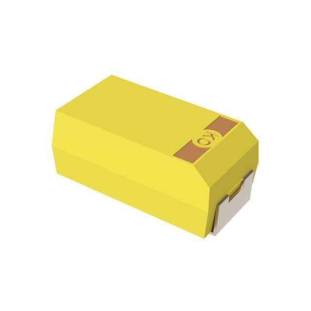
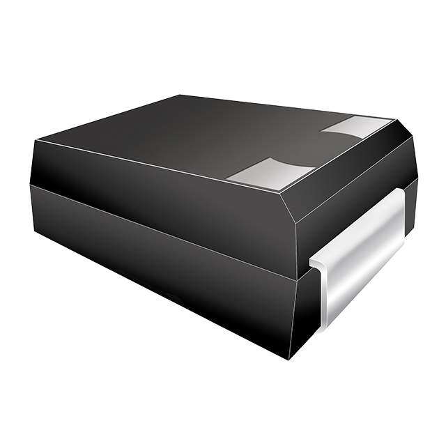
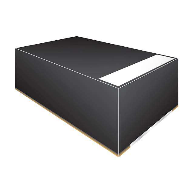
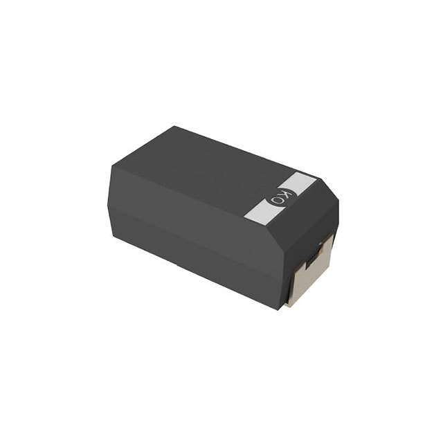
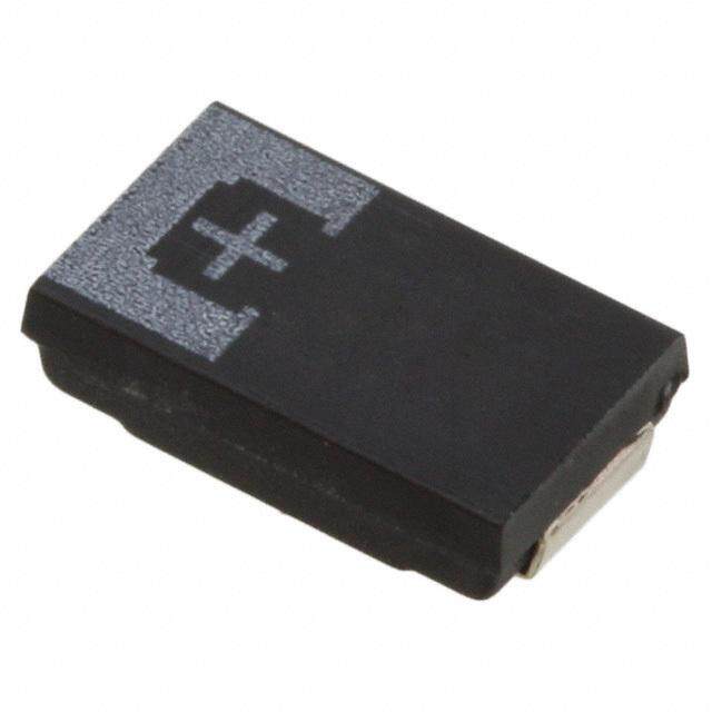
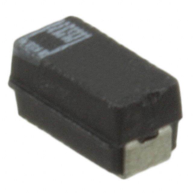
ICGOO电子元器件商城为您提供T543X337M016AHE025由Kemet设计生产,在icgoo商城现货销售,并且可以通过原厂、代理商等渠道进行代购。 T543X337M016AHE025价格参考。KemetT543X337M016AHE025封装/规格:钽 - 聚合物电容器, 330µF 模制 聚合物钽电容器 16V 2917(7343 公制) 25 毫欧 @ 100kHz。您可以下载T543X337M016AHE025参考资料、Datasheet数据手册功能说明书,资料中有T543X337M016AHE025 详细功能的应用电路图电压和使用方法及教程。
KEMET品牌的钽-聚合物电容器,型号为T543X337M016AHE025,是一种高性能的固态电解电容器。以下是该型号电容器的主要应用场景:

 1. 电源滤波
   - 该型号电容器具有低ESR(等效串联电阻)和高纹波电流能力,非常适合用于电源电路中的滤波。例如,在DC-DC转换器、开关电源(SMPS)或线性稳压器中,它可以有效降低电压纹波,提高电源稳定性。

 2. 信号耦合与去耦
   - 在高频电路中,T543X337M016AHE025可用于信号耦合和去耦。它能够隔离直流成分,同时允许交流信号通过,适用于音频放大器、射频(RF)电路和其他高速信号处理场景。

 3. 消费电子设备
   - 这款电容器广泛应用于消费电子产品中,如智能手机、平板电脑、笔记本电脑和电视。它的小型化设计(2512封装)和高可靠性使其成为紧凑型电子设备的理想选择。

 4. 工业控制
   - 在工业自动化和控制系统中,该电容器可用于滤波和储能,确保系统在高噪声环境下的稳定运行。例如,它可用于可编程逻辑控制器(PLC)、变频器和伺服驱动器等设备。

 5. 通信设备
   - T543X337M016AHE025适用于通信基站、路由器和交换机等设备中的电源管理和信号处理模块。其宽温度范围(-55°C至+105°C)和高稳定性使其能够在恶劣环境下可靠工作。

 6. 汽车电子
   - 在汽车电子领域,该型号电容器可用于车载信息娱乐系统、导航设备和传感器模块中。其抗振动和抗冲击能力强,适合复杂的汽车应用环境。

 7. 医疗设备
   - 该电容器还可用于便携式医疗设备(如血压计、血糖仪)和诊断设备(如超声波仪器)中,提供稳定的电源支持和信号处理能力。

 总结
T543X337M016AHE025凭借其优异的电气性能、小型化设计和高可靠性,适用于多种场景,包括电源管理、信号处理、消费电子、工业控制、通信设备、汽车电子和医疗设备等领域。其330µF的容量和16V的工作电压使其成为需要高容量、低ESR和高稳定性的应用的理想选择。
| 参数 | 数值 |
| 产品目录 | |
| 描述 | CAP TANT 330UF 16V 20% 2917钽质电容器-SMD聚合物 16volts 330uF 20% ESR=25 |
| ESR | 25 mOhms |
| ESR(等效串联电阻) | 25 毫欧 |
| 产品分类 | |
| 品牌 | Kemet |
| 产品手册 | |
| 产品图片 |
|
| rohs | 否含铅 / 不符合限制有害物质指令(RoHS)规范要求 |
| 产品系列 | 高分子电容器,钽质电容器-SMD聚合物,Kemet T543X337M016AHE025KO Cap T543 |
| 数据手册 | |
| 产品型号 | T543X337M016AHE025 |
| 不同温度时的使用寿命 | - |
| 产品种类 | 钽质电容器-SMD聚合物 |
| 其它名称 | 399-8852-2 |
| 制造商尺寸代码 | X |
| 制造商库存号 | X Case |
| 包装 | 带卷 (TR) |
| 商标 | Kemet |
| 外壳代码-in | 2917 |
| 外壳代码-mm | 7343 |
| 外壳宽度 | 4.3 mm |
| 外壳长度 | 7.3 mm |
| 大小/尺寸 | 0.287" 长 x 0.169" 宽(7.30mm x 4.30mm) |
| 安装类型 | 表面贴装 |
| 容差 | ±20% |
| 封装 | Reel |
| 封装/外壳 | 2917(7343 公制) |
| 封装/箱体 | 2917 (7343 metric) |
| 工作温度 | -55°C ~ 105°C |
| 工厂包装数量 | 500 |
| 引线间距 | - |
| 损耗因数DF | 10 |
| 标准包装 | 500 |
| 漏泄电流 | 528 uA |
| 特性 | COTS(高可靠性) |
| 电压-额定 | 16V |
| 电压额定值 | 16 V |
| 电容 | 330µF |
| 端接类型 | SMD/SMT |
| 类型 | 模制 |
| 系列 | T543 |
| 高度 | 4 mm |
| 高度-安装(最大值) | 0.169"(4.30mm) |


- 商务部:美国ITC正式对集成电路等产品启动337调查
- 曝三星4nm工艺存在良率问题 高通将骁龙8 Gen1或转产台积电
- 太阳诱电将投资9.5亿元在常州建新厂生产MLCC 预计2023年完工
- 英特尔发布欧洲新工厂建设计划 深化IDM 2.0 战略
- 台积电先进制程称霸业界 有大客户加持明年业绩稳了
- 达到5530亿美元!SIA预计今年全球半导体销售额将创下新高
- 英特尔拟将自动驾驶子公司Mobileye上市 估值或超500亿美元
- 三星加码芯片和SET,合并消费电子和移动部门,撤换高东真等 CEO
- 三星电子宣布重大人事变动 还合并消费电子和移动部门
- 海关总署:前11个月进口集成电路产品价值2.52万亿元 增长14.8%

PDF Datasheet 数据手册内容提取
KEMET Organic Capacitor (KO-CAP®) – High Reliability T543 Up-Screen Commercial Polymer Electrolytic, 2.5 – 63 VDC Overview The KEMET Organic Capacitor (KO-CAP) is a solid The T543 COTS Polymer Electrolytic capacitor is an electrolytic capacitor with a conductive polymer cathode upscreened version of the industrial T520 KO-CAP. The capable of delivering very low ESR and improved T543's upscreened option includes surge current testing of capacitance retention at high frequencies. KO-CAP 10 cycles at +25°C and 10 cycles at -55°C/+85°C. In addition combines the low ESR of multilayer ceramic, the high to 100% Tin (Sn) terminations, a tin-lead (SnPb) option is capacitance of aluminum electrolytic, and the volumetric also available. The recommended application derating for efficiency of tantalum into a single surface mount package. these capacitors is 10 – 20%, rendering them suitable for Unlike liquid electrolyte-based capacitors, KO-CAP application voltages from 2.25 to 50 VDC. has a very long operational life and high ripple current capabilities. Benefits • Extremely low ESR • High frequency capacitance retention • 100% accelerated steady state aging • 100% surge current tested • Tape & Reel standard packaging per EIA 481 • Volumetrically efficienct • Surge options at 25°C and −55°C/+85°C • EIA standard case sizes • Halogen-free epoxy and RoHS compliant Applications Typical applications include DC/DC converters, switch mode and point of load power supply, radar pulse capacitor, and telecommunications (mobile phone and base station). Other general applications include decoupling and filtering in applications requiring low ESR or a benign failure mode. When extreme temperatures and humidity are taken into account, polymer tantalum capacitors offer a number of advantages over other types of capacitors, when used in extreme environments. KEMET continues to investigate the behavior of polymer tantalum capacitors in extreme conditions. If you have questions about using these capacitors in a specific environment or application, we suggest you contact your local representative or field application engineer to discuss the specific details of your application (see “Considerations for Polymer Capacitors in Extreme Environments” located at www.kemet.com/ExtremePolymerPaper). One world. One KEMET © KEMET Electronics Corporation • KEMET Tower • One East Broward Boulevard T2061_T543 • 2/13/2020 1 Fort Lauderdale, FL 33301 USA • 954-766-2800 • www.kemet.com
KEMET Organic Capacitor (KO-CAP®) – High Reliability T543 Up-Screen Commercial Polymer Electrolytic, 2.5 – 63 VDC Environmental Compliance RoHS compliant (6/6) according to Directive 2002/95/EC when ordered with 100% Sn solder. K-SIM For a detailed analysis of specific part numbers, please visit ksim.kemet.com to access KEMET’s K-SIM software. KEMET K-SIM is designed to simulate behavior of components with respect to frequency, ambient temperature, and DC bias levels. Ordering Information T 543 D 156 K 035 A H E 100 Capacitor Case Capacitance Code Capacitance Rated Voltage Failure Rate/ Termination Packaging Series Surge ESR Class Size (pF) Tolerance (VDC) Design Finish (C-Spec) T = Polymer A,B, First two digits K = ±10% 2R5 = 2.5 A = N/A H = Standard E = None ESR in Blank = 7" reel Tantalum Tantalum C, D, represent significant M = ±20% 003 = 3 solder coated S = 10 cycles mΩ 7280 = 13" reel COTS H, L, figures. Third digit 004 = 4 (SnPb 5% Pb 25°C 7610 = Bulk Bag M, O, specifies number of 006 = 6.3 minimum) W = 10 cycles 7640 = Bulk T, U, zeros. 010 = 10 T = 100% tin −55°C and plastic box V, W, 12R = 12.5 (Sn) 85°C WAFL = Waffle X, Y 016 = 16 pack 020 = 20 025 = 25 035 = 35 050 = 50 063 =63 Performance Characteristics Item Performance Characteristics Operating Temperature −55°C to 105°C/125°C (refer to part number for maximum temperature rating) Rated Capacitance Range 4.7 – 2,000 μF at 120 Hz/25°C Capacitance Tolerance K tolerance (10%), M tolerance (20%) Rated Voltage Range 2.5 – 63 V DF (120 Hz) Refer to Part Number Electrical Specification Table ESR (100 kHz) Refer to Part Number Electrical Specification Table Leakage Current ≤ 0.1 CV (µA) at rated voltage after 5 minutes © KEMET Electronics Corporation • KEMET Tower • One East Broward Boulevard T2061_T543 • 2/13/2020 22 Fort Lauderdale, FL 33301 USA • 954-766-2800 • www.kemet.com
KEMET Organic Capacitor (KO-CAP®) – High Reliability T543 Up-Screen Commercial Polymer Electrolytic, 2.5 – 63 VDC Qualification Test Condition Characteristics Δ C/C Within −20/+10 of initial value 105°C at rated voltage, 2,000 hours DF Within initial limits Endurance 125°C at 2/3 rated voltage, 2,000 hours** DCL Within 1.25 x initial limit ESR Within 2.0 x initial limit Δ C/C Within −20/+10 of initial value 105°C at 0 volts, 2,000 hours DF Within initial limits Storage Life 125°C at 0 volts, 2,000 hours** DCL Within 1.25 x initial limit ESR Within 2.0 x initial limit Δ C/C Within −5%/+35% of initial value DF Within initial limits Humidity 60°C, 90% RH, 500 hours DCL Within 5.0 x initial limit ESR Within 2.0 x initial limit +25°C −55°C +85°C +105°C Extreme temperature exposure at a succession of continuous steps Δ C/C IL* ±20% ±20% ±30% Temperature Stability at +25°C, −55°C, +25°C, +85°C, DF IL IL 1.2 x IL 1.5 x IL +105°C/+125°C**, +25° C DCL IL N/A 10 x IL 10 x IL Δ C/C Within −20/+10 of initial value DF Within initial limits Surge Voltage 105°C, 1.32 x rated voltage, 1,000 cycles DCL Within initial limits ESR Within initial limits Δ C/C Within ±10 of initial value MIL–STD–202, Method 213, Condition I, 100 G peak Mechanical Shock/ MIL–STD–202, Method 204, Condition D, 10 Hz to DF Within initial limits Vibration 2,000 Hz, 20 G peak DCL Within initial limits *IL = Initial limit **Refer to part number specifications for individual temperature classification © KEMET Electronics Corporation • KEMET Tower • One East Broward Boulevard T2061_T543 • 2/13/2020 33 Fort Lauderdale, FL 33301 USA • 954-766-2800 • www.kemet.com
KEMET Organic Capacitor (KO-CAP®) – High Reliability T543 Up-Screen Commercial Polymer Electrolytic, 2.5 – 63 VDC Reliability KO-CAP capacitors have an average failure rate of 0.5 %/1,000 hours at category voltage, U , and category temperature, C T . These capacitors are qualified using industry test standards at U and T . The minimum test time (1,000 hours or 2,000 C C C hours) is dependent on the product. The actual life expectancy of KO-CAP capacitors increases when application voltage, U , and application temperature, T , A A are lower than U and T . As a general guideline, when U < 0.9 * U and T < 85°C, the life expectancy will typically exceed C C A C A the useful lifetime of most hardware (> 10 years). The lifetime of a KO-CAP capacitor at a specific application voltage and temperature can be modeled using the equations below. A failure is defined as passing enough current to blow a 1-amp fuse. The calculation is an estimation based on empirical results and is not a guarantee. (U )n [E ( 1 1 )] VAF = C a U TAF = e k 273+T 273+T A A C where: where: TAF = acceleration factor due to temperature, unitless VAF = acceleration factor due to voltage, unitless E = activation energy, 1.4 eV U = category voltage, volt a C k = Boltzmann’s constant, 8.617E-5 eV/K U = application voltage, volt T = application temperature, °C A A n = exponent, 16 T = category temperature, °C C AF = VAF * TAF Life = Life * AF U ,T U ,T A A C C where: where: Life = guaranteed life application voltage UA, TA AF = acceleration factor, unitless and temperature, years TAF = accerlation factor due to temperature, unitless Life = guaranteed life category voltage UC, TC and temperature, years VAF = acceleration factor due to voltage, unitless AF = acceleration factor, unitless Terms: Category voltage, U : maximum recommended peak DC operating voltage for continuous operation at the category temperature, T C C Rated voltage, U : maximum recommended peak DC operating voltage for continuous operation up to the rated temperature, T R R Category temperature, T : maximum recommended operating temperature. Voltage derating may be required at T C C Rated temperature, T : maximum recommended operating temperature without voltage derating. T is equal to or lower than T R R C Reliability Table 1 – Common temperature range classifications 85°C (TR) / Rated Voltage (UR) 2.5 4.0 6.3 8.0 10.0 12.5 16.0 20.0 25.0 35.0 50.0 63.0 75.0 85°C (TC) Category Voltage (UC) 2.5 4.0 6.3 8.0 10.0 12.5 16.0 20.0 25.0 35.0 50.0 63.0 75.0 105°C (TR) / Rated Voltage (UR) 2.5 4.0 6.3 8.0 10.0 12.5 16.0 20.0 25.0 35.0 50.0 63.0 75.0 105°C (TC) Category Voltage (UC) 2.5 4.0 6.3 8.0 10.0 12.5 16.0 20.0 25.0 35.0 50.0 63.0 75.0 105°C (TR) / Rated Voltage (UR) 2.5 4.0 6.3 8.0 10.0 12.5 16.0 20.0 25.0 35.0 50.0 63.0 75.0 125°C (TC) Category Voltage (UC) 1.7 2.7 4.2 5.4 6.7 8.4 10.7 13.4 16.8 23.5 33.5 42.2 50.3 © KEMET Electronics Corporation • KEMET Tower • One East Broward Boulevard T2061_T543 • 2/13/2020 44 Fort Lauderdale, FL 33301 USA • 954-766-2800 • www.kemet.com
KEMET Organic Capacitor (KO-CAP®) – High Reliability T543 Up-Screen Commercial Polymer Electrolytic, 2.5 – 63 VDC Electrical Characteristics ESR vs. Frequency 100 T5430B157M006ATE035_Imp T543C227M006ATE025_Imp T543V337M006ATE015_Imp ) 10 s T543D337M006ATE009_Imp m T543B157M006ATE035_ESR h O T543C227M006ATE025_ESR ( R 1 T543V337M006ATE015_ESR S T543D337M006ATE009_ESR E , e c n 0.1 a d e p m 0.01 I 0.001 100 1,000 10,000 100,000 1,000,000 10,000,000 Frequency (Hz) Capacitance vs. Frequency 1,000 ) F µ 100 ( e c n a t i c a p a 10 C T543B157M006ATE035 T543C227M006ATE025 T543V337M006ATE015 T543D337M006ATE009 1 100 1,000 10,000 100,000 1,000,000 10,000,000 Frequency (Hz) © KEMET Electronics Corporation • KEMET Tower • One East Broward Boulevard T2061_T543 • 2/13/2020 55 Fort Lauderdale, FL 33301 USA • 954-766-2800 • www.kemet.com
KEMET Organic Capacitor (KO-CAP®) – High Reliability T543 Up-Screen Commercial Polymer Electrolytic, 2.5 – 63 VDC Dimensions – Millimeters CATHODE (-) END VIEW SIDE VIEW ANODE (+) END VIEW BOTTOM VIEW A W B B Glue pad H E shape/design at F KEMET's option P Termination cutout X T S G S at KEeMitEhTer's e onpdtion, R L Typical Case Size Component Dimensions Weight B ±0.15 F ±0.1 S ±0.3 X P R T A G E KEMET EIA L W H (Ref) (mg) ±(0.004) ±(0.012) (Ref) (Ref) (Ref) (Ref) (Min) (Ref) (Ref) ±0.006 1.6±0.2 A 3216–18 3.2±0.2 (0.063 1.6±0.2 1.2 0.8 0.4 0.10±0.10 0.4 0.4 0.13 1.2 1.1 1.3 53.17 (0.126±0.008) (0.063±0.008) (0.047) (0.031) (0.016) (0.004±0.004) (0.016) (0.016) (0.005) (0.047) (0.043) (0.051) ±0.008) B 3528–21 3.5±0.2 2.8±0.2 1.9±0.2 2.2 0.8 0.4 0.10±0.10 0.5 1.0 0.13 1.9 1.8 2.2 98.30 (0.138±0.008)(0.110±0.008) (0.075±0.008) (0.087) (0.031) (0.016) (0.004±0.004) (0.020) (0.039) (0.005) (0.075) (0.071) (0.087) C 6032–28 6.0±0.3 3.2±0.2 2.5±0.3 2.2 1.3 0.5 0.10±0.10 0.9 1.0 0.13 3.1 2.8 2.4 193.46 (0.236±0.012)(0.126±0.008) (0.098±0.012) (0.087) (0.051) (0.020) (0.004±0.004) (0.035) (0.039) (0.005) (0.122) (0.110) (0.094) D 7343–31 7.3±0.3 4.3±0.3 2.8±0.3 2.4 1.3 0.5 0.10±0.10 0.9 1.0 0.13 3.8 3.5 3.5 352.36 (0.287±0.012)(0.169±0.012) (0.110±0.012) (0.094) (0.051) (0.020) (0.004±0.004) (0.035) (0.039) (0.005) (0.150) (0.138) (0.138) H 7360–20 7.3±0.3 6.0±0.3 1.9±0.1 4.1 1.3 N/A 0.10±0.10 N/A N/A 0.13 3.8 3.5 3.5 366.62 (0.287±0.012)(0.236±0.012) (0.075±0.004) (0.161) (0.051) (0.004±0.004) (0.005) (0.150) (0.138) (0.138) L 6032–19 6.0±0.3 3.2±0.2 1.8±0.1 2.2 1.3 N/A 0.05 N/A N/A 0.13 3.1 2.8 2.4 No data (0.236±0.012)(0.110±0.008) (0.071±0.004) (0.087) (0.051) (0.002) (0.005) (0.122) (0.110) (0.094) M 3528–15 3.5±0.2 2.8±0.2 1.4±0.1 2.2 0.8 N/A 0.05 N/A N/A 0.13 1.9 1.8 2.2 97.99 (0.138±0.008)(0.110±0.008) (0.055±0.004) (0.087) (0.031) (0.002) (0.005) (0.075) (0.071) (0.087) O 7360-43 7.3±0.3 6.0±0.3 4.0±0.3 4.1 1.3 N/A 0.10 ±0.10 N/A N/A 0.13 3.8 3.5 3.5 696.00 (0.287±0.012)(0.236±0.012) (0.157±0.012) (0.161) (0.051) (0.004±0.004) (0.005) (0.150) (0.138) (0.138) T 3528–12 3.5±0.2 2.8±0.2 1.1±0.1 2.2 0.8 N/A 0.05 N/A N/A 0.13 1.9 1.8 2.2 59.38 (0.138±0.008)(0.110±0.008) (0.043±0.004) (0.087) (0.031) (0.002) (0.005) (0.075) (0.071) (0.087) U 6032–15 6.0±0.3 3.2±0.2 1.4±0.1 2.2 1.3 N/A 0.05 N/A N/A 0.13 3.1 2.8 2.4 No data (0.236±0.012)(0.110±0.008) (0.055±0.004) (0.087) (0.051) (0.002) (0.005) (0.122) (0.110) (0.094) V 7343–20 7.3±0.3 4.3±0.3 1.9±0.1 2.4 1.3 N/A 0.05 N/A N/A 0.13 3.8 3.5 3.5 262.90 (0.287±0.012)(0.169±0.012) (0.075±0.004) (0.094) (0.051) (0.002) (0.005) (0.150) (0.138) (0.138) W 7343–15 7.3±0.3 4.3±0.3 1.4±0.1 2.4 1.3 N/A 0.05 N/A N/A 0.13 3.8 3.5 3.5 222.94 (0.287±0.012)(0.169±0.012) (0.055 ±0.004) (0.094) (0.051) (0.002) (0.005) (0.150) (0.138) (0.138) X 7343–43 7.3±0.3 4.3±0.3 4.0±0.3 2.4 1.3 0.5 0.10±0.10 1.7 1.0 0.13 3.8 3.5 3.5 588.16 (0.287±0.012)(0.169±0.012) (0.157±0.012) (0.094) (0.051) (0.020) (0.004±0.004) (0.067) (0.039) (0.005) (0.150) (0.138) (0.138) Y 7343–40 7.3±0.3 4.3±0.3 3.8±0.2 2.4 1.3 0.5 0.10±0.10 1.7 1.0 0.13 3.8 3.5 3.5 481.55 (0.287±0.012)(0.169±0.012) (0.150±0.008) (0.094) (0.051) (0.020) (0.004±0.004) (0.067) (0.039) (0.005) (0.150) (0.138) (0.138) Notes: (Ref) – Dimensions provided for reference only. For low profile cases, no dimensions are provided for B, P, or R because these cases do not have a bevel or a notch. These weights are provided as reference. If exact weights are needed, please contact your KEMET Sales Representative. © KEMET Electronics Corporation • KEMET Tower • One East Broward Boulevard T2061_T543 • 2/13/2020 66 Fort Lauderdale, FL 33301 USA • 954-766-2800 • www.kemet.com
KEMET Organic Capacitor (KO-CAP®) – High Reliability T543 Up-Screen Commercial Polymer Electrolytic, 2.5 – 63 VDC Table 1 – Ratings & Part Number Reference Rated Case Maximum Maximum Voltage Rated Code/ KEMET Part DC DF ESR Allowable Operating MSL VDC at Cap Case Number Leakage Ripple Current Temp. 105°C Size Not all (See below for µA at VR, 25°C % at 25°C mΩ at 25°C (rms) Reflow Temp parts are µF KEMET/EIA Maximum/ 120 Hz 100 kHz mA at 45°C °C 105°C rated part options) 5 Minutes Maximum Maximum 100 kHz ≤ 260°C 2.5 47 A/3216-18 T543A476(1)2R5A(2)(3)090 12 8 90 1,116 105 3 2.5 56 T/3528-12 T543T566(1)2R5A(2)(3)040 14 8 40 1,620 105 3 2.5 56 T/3528-12 T543T566(1)2R5A(2)(3)070 14 8 70 1,225 105 3 2.5 68 A/3216-18 T543A686(1)2R5A(2)(3)070 17 8 70 1,265 105 3 2.5 68 A/3216-18 T543A686(1)2R5A(2)(3)080 17 8 80 1,183 105 3 2.5 100 T/3528-12 T543T107(1)2R5A(2)(3)040 25 8 40 1,620 105 3 2.5 100 T/3528-12 T543T107(1)2R5A(2)(3)070 25 8 70 1,225 105 3 2.5 100 T/3528-12 T543T107(1)2R5A(2)(3)080 25 8 80 1,146 105 3 2.5 100 B/3528-21 T543B107(1)2R5A(2)(3)025 25 8 25 2,254 105 3 2.5 100 B/3528-21 T543B107(1)2R5A(2)(3)035 25 8 35 1,905 105 3 2.5 100 B/3528-21 T543B107(1)2R5A(2)(3)040 25 8 40 1,782 105 3 2.5 100 B/3528-21 T543B107(1)2R5A(2)(3)070 25 8 70 1,347 105 3 2.5 150 U/6032-15 T543U157(1)2R5A(2)(3)055 38 8 55 1,567 105 3 2.5 220 B/3528-21 T543B227(1)2R5A(2)(3)025 55 8 25 2,254 105 3 2.5 220 B/3528-21 T543B227(1)2R5A(2)(3)030 55 8 30 2,058 105 3 2.5 220 B/3528-21 T543B227(1)2R5A(2)(3)035 55 8 35 1,905 105 3 2.5 220 B/3528-21 T543B227(1)2R5A(2)(3)055 55 8 55 1,520 105 3 2.5 220 B/3528-21 T543B227(1)2R5A(2)(3)070 55 8 70 1,347 105 3 2.5 220 U/6032-15 T543U227(1)2R5A(2)(3)055 55 8 55 1,567 105 3 2.5 220 C/6032-28 T543C227(1)2R5A(2)(3)025 55 8 25 2,569 105 3 2.5 220 C/6032-28 T543C227(1)2R5A(2)(3)045 55 8 45 1,915 105 3 2.5 220 W/7343-15 T543W227(1)2R5A(2)(3)025 55 10 25 2,683 105 3 2.5 220 V/7343-20 T543V227(1)2R5A(2)(3)015 55 10 15 3,531 105 3 2.5 220 V/7343-20 T543V227(1)2R5A(2)(3)025 55 10 25 2,735 105 3 2.5 220 V/7343-20 T543V227(1)2R5A(2)(3)045 55 10 45 2,039 105 3 2.5 220 D-7343-31 T543D227(1)2R5A(2)(3)040 55 10 40 2,372 105 3 2.5 330 B/3528-21 T543B337(1)2R5A(2)(3)035 83 8 35 1,905 105 3 2.5 330 B/3528-21 T543B337(1)2R5A(2)(3)045 83 8 45 1,680 105 3 2.5 330 B/3528-21 T543B337(1)2R5A(2)(3)070 83 8 70 1,347 105 3 2.5 330 L/6032-19 T543L337(1)2R5A(2)(3)012 83 8 12 3,536 105 3 2.5 330 L/6032-19 T543L337(1)2R5A(2)(3)025 83 8 25 2,449 105 3 2.5 330 C/6032-28 T543C337(1)2R5A(2)(3)015 83 8 15 3,317 105 3 2.5 330 C/6032-28 T543C337(1)2R5A(2)(3)018 83 8 18 3,028 105 3 2.5 330 C/6032-28 T543C337(1)2R5A(2)(3)025 83 8 25 2,569 105 3 2.5 330 C/6032-28 T543C337(1)2R5A(2)(3)045 83 8 45 1,915 105 3 2.5 330 W/7343-15 T543W337(1)2R5A(2)(3)015 83 10 15 3,464 105 3 2.5 330 W/7343-15 T543W337(1)2R5A(2)(3)025 83 10 25 2,683 105 3 2.5 330 W/7343-15 T543W337(1)2R5A(2)(3)040 83 10 40 2,121 105 3 2.5 330 V/7343-20 T543V337(1)2R5A(2)(3)015 83 10 15 3,531 105 3 2.5 330 V/7343-20 T543V337(1)2R5A(2)(3)018 83 10 18 3,223 105 3 2.5 330 V/7343-20 T543V337(1)2R5A(2)(3)025 83 10 25 2,735 105 3 2.5 330 V/7343-20 T543V337(1)2R5A(2)(3)040 83 10 40 2,162 105 3 2.5 330 D-7343-31 T543D337(1)2R5A(2)(3)006 83 10 6 6,124 105 3 2.5 330 D-7343-31 T543D337(1)2R5A(2)(3)007 83 10 7 5,669 105 3 2.5 330 D-7343-31 T543D337(1)2R5A(2)(3)025 83 10 25 3,000 105 3 2.5 470 C/6032-28 T543C477(1)2R5A(2)(3)025 118 8 25 2,569 105 3 2.5 470 C/6032-28 T543C477(1)2R5A(2)(3)045 118 8 45 1,915 105 3 2.5 470 V/7343-20 T543V477(1)2R5A(2)(3)018 118 10 18 3,223 105 3 2.5 470 D-7343-31 T543D477(1)2R5A(2)(3)005 118 10 5 6,708 105 3 2.5 470 D-7343-31 T543D477(1)2R5A(2)(3)006 118 10 6 6,124 105 3 µA at V, 25°C % at 25°C mΩ at 25°C (rms) (See below for R Reflow Temp VDC at 105°C µF KEMET/EIA Maximum/ 120 Hz 100 kHz mA at 45°C °C part options) ≤ 260°C 5 Minutes Maximum Maximum 100 kHz Rated Rated Case Code/ Maximum Allowable Maximum KEMET Part Number DC Leakage DF ESR MSL Voltage Capacitance Case Size Ripple Current Operating Temp. (1) To complete KEMET part number, insert M for ±20%, K for ±10%. Designates capacitance tolerance. (2) To complete KEMET part number, H = Solder-Plated, T = 100% Tin (Sn). Designates termination finish. (3) To complete KEMET part number, insert E = None, S = 10 cycles +25°C, W = 10 cycles −55°C +85°C. Designates surge current option. Refer to Ordering Information for additional detail. Part Numbers marked in blue font are "Under Development." Engineering samples available upon request. © KEMET Electronics Corporation • KEMET Tower • One East Broward Boulevard T2061_T543 • 2/13/2020 77 Fort Lauderdale, FL 33301 USA • 954-766-2800 • www.kemet.com
KEMET Organic Capacitor (KO-CAP®) – High Reliability T543 Up-Screen Commercial Polymer Electrolytic, 2.5 – 63 VDC Table 1 – Ratings & Part Number Reference cont. Rated Case Maximum Maximum Voltage Rated Code/ KEMET Part DC DF ESR Allowable Operating MSL VDC at Cap Case Number Leakage Ripple Current Temp. 105°C Size Not all (See below for µA at VR, 25°C % at 25°C mΩ at 25°C (rms) Reflow Temp parts are µF KEMET/EIA Maximum/ 120 Hz 100 kHz mA at 45°C °C 105°C rated part options) 5 Minutes Maximum Maximum 100 kHz ≤ 260°C 2.5 470 D-7343-31 T543D477(1)2R5A(2)(3)007 118 10 7 5,669 105 3 2.5 470 D-7343-31 T543D477(1)2R5A(2)(3)009 118 10 9 5,000 105 3 2.5 470 D-7343-31 T543D477(1)2R5A(2)(3)010 118 10 10 4,743 105 3 2.5 470 D-7343-31 T543D477(1)2R5A(2)(3)025 118 10 25 3,000 105 3 2.5 560 D-7343-31 T543D567(1)2R5A(2)(3)005 140 10 5 6,708 105 3 2.5 680 D-7343-31 T543D687(1)2R5A(2)(3)006 170 10 6 6,124 125 3 2.5 680 D-7343-31 T543D687(1)2R5A(2)(3)010 170 10 10 4,743 125 3 2.5 680 D-7343-31 T543D687(1)2R5A(2)(3)015 170 10 15 3,873 125 3 2.5 680 D-7343-31 T543D687(1)2R5A(2)(3)040 170 10 40 2,372 125 3 2.5 680 Y/7343-40 T543Y687(1)2R5A(2)(3)005 170 10 5 6,943 105 3 2.5 680 Y/7343-40 T543Y687(1)2R5A(2)(3)006 170 10 6 6,338 105 3 2.5 680 Y/7343-40 T543Y687(1)2R5A(2)(3)010 170 10 10 4,909 105 3 2.5 680 Y/7343-40 T543Y687(1)2R5A(2)(3)015 170 10 15 4,008 105 3 2.5 680 Y/7343-40 T543Y687(1)2R5A(2)(3)025 170 10 25 3,105 105 3 2.5 680 X/7343-43 T543X687(1)2R5A(2)(3)006 170 10 6 6,416 105 3 2.5 1000 Y/7343-40 T543Y108(1)2R5A(2)(3)005 250 10 5 6,943 105 3 2.5 1000 Y/7343-40 T543Y108(1)2R5A(2)(3)006 250 10 6 6,338 105 3 2.5 1000 Y/7343-40 T543Y108(1)2R5A(2)(3)010 250 10 10 4,909 105 3 2.5 1000 Y/7343-40 T543Y108(1)2R5A(2)(3)015 250 10 15 4,008 105 3 2.5 1000 Y/7343-40 T543Y108(1)2R5A(2)(3)025 250 10 25 3,105 105 3 2.5 1000 X/7343-43 T543X108(1)2R5A(2)(3)005 250 10 5 7,029 105 3 2.5 1000 X/7343-43 T543X108(1)2R5A(2)(3)006 250 10 6 6,416 105 3 2.5 1000 X/7343-43 T543X108(1)2R5A(2)(3)010 250 10 10 4,970 105 3 2.5 1500 X/7343-43 T543X158(1)2R5A(2)(3)005 375 10 5 7,029 105 3 2.5 1500 X/7343-43 T543X158(1)2R5A(2)(3)010 375 10 10 4,970 105 3 3 100 B/3528-21 T543B107(1)003A(2)(3)035 30 8 35 1,905 105 3 3 100 B/3528-21 T543B107(1)003A(2)(3)040 30 8 40 1,782 105 3 3 100 B/3528-21 T543B107(1)003A(2)(3)070 30 8 70 1,347 105 3 3 100 B/3528-21 T543B107(1)003A(2)(3)080 30 8 80 1,260 105 3 3 150 B/3528-21 T543B157(1)003A(2)(3)035 45 8 35 1,905 105 3 3 150 B/3528-21 T543B157(1)003A(2)(3)040 45 8 40 1,782 105 3 3 150 B/3528-21 T543B157(1)003A(2)(3)070 45 8 70 1,347 105 3 3 150 B/3528-21 T543B157(1)003A(2)(3)080 45 8 80 1,260 105 3 3 330 V/7343-20 T543V337(1)003A(2)(3)015 99 10 15 3,531 105 3 3 330 V/7343-20 T543V337(1)003A(2)(3)025 99 10 25 2,735 105 3 3 330 D-7343-31 T543D337(1)003A(2)(3)025 99 10 25 3,000 105 3 3 470 D-7343-31 T543D477(1)003A(2)(3)010 141 10 10 4,743 105 3 3 470 D-7343-31 T543D477(1)003A(2)(3)025 141 10 25 3,000 105 3 3 680 D-7343-31 T543D687(1)003A(2)(3)010 204 10 10 4,743 125 3 3 680 D-7343-31 T543D687(1)003A(2)(3)015 204 10 15 3,873 125 3 3 680 D-7343-31 T543D687(1)003A(2)(3)025 204 10 25 3,000 125 3 3 680 D-7343-31 T543D687(1)003A(2)(3)040 204 10 40 2,372 125 3 3 1000 X/7343-43 T543X108(1)003A(2)(3)010 300 10 10 4,970 105 3 3 1000 X/7343-43 T543X108(1)003A(2)(3)015 300 10 15 4,058 105 3 3 1000 X/7343-43 T543X108(1)003A(2)(3)030 300 10 30 2,869 105 3 3 1500 X/7343-43 T543X158(1)003A(2)(3)008 450 10 8 5,557 125 3 3 2000 O/7360-43 T543O208M003A(2)(3)010 600 10 10 5,480 105 3 4 15 T/3528-12 T543T156(1)004A(2)(3)100 6 8 100 1,025 105 3 4 33 A/3216-18 T543A336(1)004A(2)(3)070 13 8 70 1,265 105 3 4 33 A/3216-18 T543A336(1)004A(2)(3)080 13 8 80 1,183 105 3 µA at V, 25°C % at 25°C mΩ at 25°C (rms) (See below for R Reflow Temp VDC at 105°C µF KEMET/EIA Maximum/ 120 Hz 100 kHz mA at 45°C °C part options) ≤ 260°C 5 Minutes Maximum Maximum 100 kHz Rated Rated Case Code/ Maximum Allowable Maximum KEMET Part Number DC Leakage DF ESR MSL Voltage Capacitance Case Size Ripple Current Operating Temp. (1) To complete KEMET part number, insert M for ±20%, K for ±10%. Designates capacitance tolerance. (2) To complete KEMET part number, H = Solder-Plated, T = 100% Tin (Sn). Designates termination finish. (3) To complete KEMET part number, insert E = None, S = 10 cycles +25°C, W = 10 cycles −55°C +85°C. Designates surge current option. Refer to Ordering Information for additional detail. Part Numbers marked in blue font are "Under Development." Engineering samples available upon request. © KEMET Electronics Corporation • KEMET Tower • One East Broward Boulevard T2061_T543 • 2/13/2020 88 Fort Lauderdale, FL 33301 USA • 954-766-2800 • www.kemet.com
KEMET Organic Capacitor (KO-CAP®) – High Reliability T543 Up-Screen Commercial Polymer Electrolytic, 2.5 – 63 VDC Table 1 – Ratings & Part Number Reference cont. Rated Case Maximum Maximum Voltage Rated Code/ KEMET Part DC DF ESR Allowable Operating MSL VDC at Cap Case Number Leakage Ripple Current Temp. 105°C Size Not all (See below for µA at VR, 25°C % at 25°C mΩ at 25°C (rms) Reflow Temp parts are µF KEMET/EIA Maximum/ 120 Hz 100 kHz mA at 45°C °C 105°C rated part options) 5 Minutes Maximum Maximum 100 kHz ≤ 260°C 4 47 A/3216-18 T543A476(1)004A(2)(3)070 19 8 70 1,265 105 3 4 47 A/3216-18 T543A476(1)004A(2)(3)080 19 8 80 1,183 105 3 4 47 T/3528-12 T543T476(1)004A(2)(3)070 19 8 70 1,225 105 3 4 68 T/3528-12 T543T686(1)004A(2)(3)070 27 8 70 1,225 105 3 4 68 T/3528-12 T543T686(1)004A(2)(3)080 27 8 80 1,146 105 3 4 68 B/3528-21 T543B686(1)004A(2)(3)035 27 8 35 1,905 105 3 4 68 B/3528-21 T543B686(1)004A(2)(3)040 27 8 40 1,782 105 3 4 68 B/3528-21 T543B686(1)004A(2)(3)070 27 8 70 1,347 105 3 4 68 B/3528-21 T543B686(1)004A(2)(3)080 27 8 80 1,260 105 3 4 68 U/6032-15 T543U686(1)004A(2)(3)055 27 8 55 1,567 105 3 4 100 A/3216-18 T543A107(1)004A(2)(3)150 40 8 150 864 105 3 4 100 A/3216-18 T543A107(1)004A(2)(3)200 40 8 200 748 105 3 4 100 T/3528-12 T543T107(1)004A(2)(3)070 40 8 70 1,225 105 3 4 100 T/3528-12 T543T107(1)004A(2)(3)150 40 8 150 837 105 3 4 100 B/3528-21 T543B107(1)004A(2)(3)035 40 8 35 1,905 105 3 4 100 B/3528-21 T543B107(1)004A(2)(3)040 40 8 40 1,782 105 3 4 100 B/3528-21 T543B107(1)004A(2)(3)070 40 8 70 1,347 105 3 4 100 B/3528-21 T543B107(1)004A(2)(3)080 40 8 80 1,260 105 3 4 100 U/6032-15 T543U107(1)004A(2)(3)055 40 8 55 1,567 105 3 4 150 B/3528-21 T543B157(1)004A(2)(3)035 60 8 35 1,905 105 3 4 150 B/3528-21 T543B157(1)004A(2)(3)040 60 8 40 1,782 105 3 4 150 B/3528-21 T543B157(1)004A(2)(3)070 60 8 70 1,347 105 3 4 150 U/6032-15 T543U157(1)004A(2)(3)055 60 8 55 1,567 105 3 4 150 C/6032-28 T543C157(1)004A(2)(3)015 60 8 15 3,317 105 3 4 150 C/6032-28 T543C157(1)004A(2)(3)025 60 8 25 2,569 105 3 4 150 C/6032-28 T543C157(1)004A(2)(3)045 60 8 45 1,915 105 3 4 150 C/6032-28 T543C157(1)004A(2)(3)100 60 8 100 1,285 105 3 4 150 V/7343-20 T543V157(1)004A(2)(3)015 60 10 15 3,531 105 3 4 150 V/7343-20 T543V157(1)004A(2)(3)025 60 10 25 2,735 105 3 4 220 B/3528-21 T543B227(1)004A(2)(3)035 88 8 35 1,905 105 3 4 220 B/3528-21 T543B227(1)004A(2)(3)045 88 8 45 1,680 105 3 4 220 B/3528-21 T543B227(1)004A(2)(3)070 88 8 70 1,347 105 3 4 220 L/6032-19 T543L227(1)004A(2)(3)012 88 8 12 3,536 105 3 4 220 L/6032-19 T543L227(1)004A(2)(3)025 88 8 25 2,449 105 3 4 220 C/6032-28 T543C227(1)004A(2)(3)015 88 8 15 3,317 105 3 4 220 C/6032-28 T543C227(1)004A(2)(3)018 88 8 18 3,028 105 3 4 220 C/6032-28 T543C227(1)004A(2)(3)025 88 8 25 2,569 105 3 4 220 C/6032-28 T543C227(1)004A(2)(3)045 88 8 45 1,915 105 3 4 220 C/6032-28 T543C227(1)004A(2)(3)055 88 8 55 1,732 105 3 4 220 W/7343-15 T543W227(1)004A(2)(3)025 88 10 25 2,683 105 3 4 220 W/7343-15 T543W227(1)004A(2)(3)040 88 10 40 2,121 105 3 4 220 V/7343-20 T543V227(1)004A(2)(3)015 88 10 15 3,531 105 3 4 220 V/7343-20 T543V227(1)004A(2)(3)018 88 10 18 3,223 105 3 4 220 V/7343-20 T543V227(1)004A(2)(3)025 88 10 25 2,735 105 3 4 220 V/7343-20 T543V227(1)004A(2)(3)040 88 10 40 2,162 105 3 4 220 V/7343-20 T543V227(1)004A(2)(3)045 88 10 45 2,039 105 3 4 220 D-7343-31 T543D227(1)004A(2)(3)025 88 10 25 3,000 105 3 4 220 D-7343-31 T543D227(1)004A(2)(3)065 88 10 65 1,861 105 3 4 330 C/6032-28 T543C337(1)004A(2)(3)025 132 8 25 2,569 105 3 4 330 C/6032-28 T543C337(1)004A(2)(3)045 132 8 45 1,915 105 3 µA at V, 25°C % at 25°C mΩ at 25°C (rms) (See below for R Reflow Temp VDC at 105°C µF KEMET/EIA Maximum/ 120 Hz 100 kHz mA at 45°C °C part options) ≤ 260°C 5 Minutes Maximum Maximum 100 kHz Rated Rated Case Code/ Maximum Allowable Maximum KEMET Part Number DC Leakage DF ESR MSL Voltage Capacitance Case Size Ripple Current Operating Temp. (1) To complete KEMET part number, insert M for ±20%, K for ±10%. Designates capacitance tolerance. (2) To complete KEMET part number, H = Solder-Plated, T = 100% Tin (Sn). Designates termination finish. (3) To complete KEMET part number, insert E = None, S = 10 cycles +25°C, W = 10 cycles −55°C +85°C. Designates surge current option. Refer to Ordering Information for additional detail. Part Numbers marked in blue font are "Under Development." Engineering samples available upon request. © KEMET Electronics Corporation • KEMET Tower • One East Broward Boulevard T2061_T543 • 2/13/2020 99 Fort Lauderdale, FL 33301 USA • 954-766-2800 • www.kemet.com
KEMET Organic Capacitor (KO-CAP®) – High Reliability T543 Up-Screen Commercial Polymer Electrolytic, 2.5 – 63 VDC Table 1 – Ratings & Part Number Reference cont. Rated Case Maximum Maximum Voltage Rated Code/ KEMET Part DC DF ESR Allowable Operating MSL VDC at Cap Case Number Leakage Ripple Current Temp. 105°C Size Not all (See below for µA at VR, 25°C % at 25°C mΩ at 25°C (rms) Reflow Temp parts are µF KEMET/EIA Maximum/ 120 Hz 100 kHz mA at 45°C °C 105°C rated part options) 5 Minutes Maximum Maximum 100 kHz ≤ 260°C 4 330 V/7343-20 T543V337(1)004A(2)(3)018 132 10 18 3,223 105 3 4 330 V/7343-20 T543V337(1)004A(2)(3)025 132 10 25 2,735 105 3 4 330 V/7343-20 T543V337(1)004A(2)(3)040 132 10 40 2,162 105 3 4 330 D-7343-31 T543D337(1)004A(2)(3)005 132 10 5 6,708 105 3 4 330 D-7343-31 T543D337(1)004A(2)(3)006 132 10 6 6,124 105 3 4 330 D-7343-31 T543D337(1)004A(2)(3)007 132 10 7 5,669 105 3 4 330 D-7343-31 T543D337(1)004A(2)(3)009 132 10 9 5,000 105 3 4 330 D-7343-31 T543D337(1)004A(2)(3)010 132 10 10 4,743 105 3 4 330 D-7343-31 T543D337(1)004A(2)(3)012 132 10 12 4,330 105 3 4 330 D-7343-31 T543D337(1)004A(2)(3)015 132 10 15 3,873 105 3 4 330 D-7343-31 T543D337(1)004A(2)(3)025 132 10 25 3,000 105 3 4 330 D-7343-31 T543D337(1)004A(2)(3)040 132 10 40 2,372 105 3 4 330 D-7343-31 T543D337(1)004A(2)(3)045 132 10 45 2,236 105 3 4 470 D-7343-31 T543D477(1)004A(2)(3)006 188 10 6 6,124 105 3 4 470 D-7343-31 T543D477(1)004A(2)(3)010 188 10 10 4,743 105 3 4 470 D-7343-31 T543D477(1)004A(2)(3)012 188 10 12 4,330 105 3 4 470 D-7343-31 T543D477(1)004A(2)(3)015 188 10 15 3,873 105 3 4 470 D-7343-31 T543D477(1)004A(2)(3)018 188 10 18 3,536 105 3 4 470 D-7343-31 T543D477(1)004A(2)(3)025 188 10 25 3,000 105 3 4 470 D-7343-31 T543D477(1)004A(2)(3)040 188 10 40 2,372 105 3 4 470 Y/7343-40 T543Y477(1)004A(2)(3)005 188 10 5 6,943 125 3 4 470 Y/7343-40 T543Y477(1)004A(2)(3)006 188 10 6 6,338 125 3 4 470 Y/7343-40 T543Y477(1)004A(2)(3)010 188 10 10 4,909 125 3 4 470 Y/7343-40 T543Y477(1)004A(2)(3)025 188 10 25 3,105 125 3 4 470 Y/7343-40 T543Y477(1)004A(2)(3)040 188 10 40 2,455 125 3 4 680 D-7343-31 T543D687(1)004A(2)(3)025 272 10 25 3,000 125 3 4 680 Y/7343-40 T543Y687(1)004A(2)(3)005 272 10 5 6,943 105 3 4 680 Y/7343-40 T543Y687(1)004A(2)(3)010 272 10 10 4,909 105 3 4 680 Y/7343-40 T543Y687(1)004A(2)(3)015 272 10 15 4,008 105 3 4 680 Y/7343-40 T543Y687(1)004A(2)(3)025 272 10 25 3,105 105 3 4 680 X/7343-43 T543X687(1)004A(2)(3)005 272 10 5 7,029 125 3 4 680 X/7343-43 T543X687(1)004A(2)(3)006 272 10 6 6,416 125 3 4 680 X/7343-43 T543X687(1)004A(2)(3)010 272 10 10 4,970 125 3 4 680 X/7343-43 T543X687(1)004A(2)(3)015 272 10 15 4,058 125 3 4 680 X/7343-43 T543X687(1)004A(2)(3)035 272 10 35 2,657 125 3 4 1000 X/7343-43 T543X108(1)004A(2)(3)006 400 10 6 6,416 105 3 4 1000 X/7343-43 T543X108(1)004A(2)(3)010 400 10 10 4,970 105 3 4 1500 O/7360-43 T543O158M004A(2)(3)010 600 10 10 5,480 105 3 6.3 15 T/3528-12 T543T156(1)006A(2)(3)100 9 8 100 1,025 105 3 6.3 22 A/3216-18 T543A226(1)006A(2)(3)090 14 8 90 1,116 105 3 6.3 22 A/3216-18 T543A226(1)006A(2)(3)100 14 8 100 1,058 105 3 6.3 33 A/3216-18 T543A336(1)006A(2)(3)070 21 8 70 1,265 105 3 6.3 33 A/3216-18 T543A336(1)006A(2)(3)080 21 8 80 1,183 105 3 6.3 33 A/3216-18 T543A336(1)006A(2)(3)120 21 8 120 966 105 3 6.3 33 T/3528-12 T543T336(1)006A(2)(3)070 21 8 70 1,225 105 3 6.3 33 B/3528-21 T543B336(1)006A(2)(3)025 21 8 25 2,254 105 3 6.3 33 B/3528-21 T543B336(1)006A(2)(3)035 21 8 35 1,905 105 3 6.3 33 B/3528-21 T543B336(1)006A(2)(3)040 21 8 40 1,782 105 3 6.3 33 B/3528-21 T543B336(1)006A(2)(3)070 21 8 70 1,347 105 3 6.3 33 B/3528-21 T543B336(1)006A(2)(3)080 21 8 80 1,260 105 3 µA at V, 25°C % at 25°C mΩ at 25°C (rms) (See below for R Reflow Temp VDC at 105°C µF KEMET/EIA Maximum/ 120 Hz 100 kHz mA at 45°C °C part options) ≤ 260°C 5 Minutes Maximum Maximum 100 kHz Rated Rated Case Code/ Maximum Allowable Maximum KEMET Part Number DC Leakage DF ESR MSL Voltage Capacitance Case Size Ripple Current Operating Temp. (1) To complete KEMET part number, insert M for ±20%, K for ±10%. Designates capacitance tolerance. (2) To complete KEMET part number, H = Solder-Plated, T = 100% Tin (Sn). Designates termination finish. (3) To complete KEMET part number, insert E = None, S = 10 cycles +25°C, W = 10 cycles −55°C +85°C. Designates surge current option. Refer to Ordering Information for additional detail. Part Numbers marked in blue font are "Under Development." Engineering samples available upon request. © KEMET Electronics Corporation • KEMET Tower • One East Broward Boulevard T2061_T543 • 2/13/2020 1100 Fort Lauderdale, FL 33301 USA • 954-766-2800 • www.kemet.com
KEMET Organic Capacitor (KO-CAP®) – High Reliability T543 Up-Screen Commercial Polymer Electrolytic, 2.5 – 63 VDC Table 1 – Ratings & Part Number Reference cont. Rated Case Maximum Maximum Voltage Rated Code/ KEMET Part DC DF ESR Allowable Operating MSL VDC at Cap Case Number Leakage Ripple Current Temp. 105°C Size Not all (See below for µA at VR, 25°C % at 25°C mΩ at 25°C (rms) Reflow Temp parts are µF KEMET/EIA Maximum/ 120 Hz 100 kHz mA at 45°C °C 105°C rated part options) 5 Minutes Maximum Maximum 100 kHz ≤ 260°C 6.3 33 C/6032-28 T543C336(1)006A(2)(3)100 21 8 100 1,285 105 3 6.3 47 A/3216-18 T543A476(1)006A(2)(3)150 30 8 150 864 105 3 6.3 47 T/3528-12 T543T476(1)006A(2)(3)070 30 8 70 1,225 105 3 6.3 47 T/3528-12 T543T476(1)006A(2)(3)080 30 8 80 1,146 105 3 6.3 47 B/3528-21 T543B476(1)006A(2)(3)025 30 8 25 2,254 125 3 6.3 47 B/3528-21 T543B476(1)006A(2)(3)035 30 8 35 1,905 105 3 6.3 47 B/3528-21 T543B476(1)006A(2)(3)040 30 8 40 1,782 105 3 6.3 47 B/3528-21 T543B476(1)006A(2)(3)070 30 8 70 1,347 105 3 6.3 47 B/3528-21 T543B476(1)006A(2)(3)080 30 8 80 1,260 105 3 6.3 68 A/3216-18 T543A686(1)006A(2)(3)150 43 8 150 864 105 3 6.3 68 T/3528-12 T543T686(1)006A(2)(3)070 43 8 70 1,225 105 3 6.3 68 T/3528-12 T543T686(1)006A(2)(3)150 43 8 150 837 105 3 6.3 68 B/3528-21 T543B686(1)006A(2)(3)025 43 8 25 2,254 105 3 6.3 68 B/3528-21 T543B686(1)006A(2)(3)035 43 8 35 1,905 105 3 6.3 68 B/3528-21 T543B686(1)006A(2)(3)040 43 8 40 1,782 105 3 6.3 68 B/3528-21 T543B686(1)006A(2)(3)070 43 8 70 1,347 105 3 6.3 68 B/3528-21 T543B686(1)006A(2)(3)080 43 8 80 1,260 105 3 6.3 68 U/6032-15 T543U686(1)006A(2)(3)055 43 8 55 1,567 105 3 6.3 68 U/6032-15 T543U686(1)006A(2)(3)070 43 8 70 1,389 105 3 6.3 68 C/6032-28 T543C686(1)006A(2)(3)100 43 8 100 1,285 105 3 6.3 100 T/3528-12 T543T107(1)006A(2)(3)070 63 8 70 1,225 105 3 6.3 100 B/3528-21 T543B107(1)006A(2)(3)025 63 8 25 2,254 105 3 6.3 100 B/3528-21 T543B107(1)006A(2)(3)035 63 8 35 1,905 105 3 6.3 100 B/3528-21 T543B107(1)006A(2)(3)040 63 8 40 1,782 105 3 6.3 100 B/3528-21 T543B107(1)006A(2)(3)045 63 8 45 1,680 105 3 6.3 100 B/3528-21 T543B107(1)006A(2)(3)070 63 8 70 1,347 105 3 6.3 100 U/6032-15 T543U107(1)006A(2)(3)055 63 8 55 1,567 105 3 6.3 100 C/6032-28 T543C107(1)006A(2)(3)025 63 8 25 2,569 105 3 6.3 100 C/6032-28 T543C107(1)006A(2)(3)045 63 8 45 1,915 105 3 6.3 100 W/7343-15 T543W107(1)006A(2)(3)040 63 10 40 2,121 105 3 6.3 100 V/7343-20 T543V107(1)006A(2)(3)015 63 10 15 3,531 105 3 6.3 100 V/7343-20 T543V107(1)006A(2)(3)045 63 10 45 2,039 105 3 6.3 120 B/3528-21 T543B127(1)006A(2)(3)035 76 8 35 1,905 105 3 6.3 150 M/3528-15 T543M157(1)006A(2)(3)070 95 8 70 1,309 105 3 6.3 150 M/3528-15 T543M157(1)006A(2)(3)150 95 8 150 894 105 3 6.3 150 B/3528-21 T543B157(1)006A(2)(3)025 95 8 25 2,254 105 3 6.3 150 B/3528-21 T543B157(1)006A(2)(3)035 95 8 35 1,905 105 3 6.3 150 B/3528-21 T543B157(1)006A(2)(3)045 95 8 45 1,680 105 3 6.3 150 B/3528-21 T543B157(1)006A(2)(3)070 95 8 70 1,347 105 3 6.3 150 U/6032-15 T543U157(1)006A(2)(3)045 95 8 45 1,732 105 3 6.3 150 U/6032-15 T543U157(1)006A(2)(3)055 95 8 55 1,567 105 3 6.3 150 L/6032-19 T543L157(1)006A(2)(3)012 95 8 12 3,536 105 3 6.3 150 L/6032-19 T543L157(1)006A(2)(3)025 95 8 25 2,449 105 3 6.3 150 C/6032-28 T543C157(1)006A(2)(3)015 95 8 15 3,317 105 3 6.3 150 C/6032-28 T543C157(1)006A(2)(3)025 95 8 25 2,569 105 3 6.3 150 C/6032-28 T543C157(1)006A(2)(3)045 95 8 45 1,915 105 3 6.3 150 C/6032-28 T543C157(1)006A(2)(3)055 95 8 55 1,732 105 3 6.3 150 W/7343-15 T543W157(1)006A(2)(3)025 95 10 25 2,683 105 3 6.3 150 W/7343-15 T543W157(1)006A(2)(3)040 95 10 40 2,121 105 3 6.3 150 V/7343-20 T543V157(1)006A(2)(3)015 95 10 15 3,531 105 3 µA at V, 25°C % at 25°C mΩ at 25°C (rms) (See below for R Reflow Temp VDC at 105°C µF KEMET/EIA Maximum/ 120 Hz 100 kHz mA at 45°C °C part options) ≤ 260°C 5 Minutes Maximum Maximum 100 kHz Rated Rated Case Code/ Maximum Allowable Maximum KEMET Part Number DC Leakage DF ESR MSL Voltage Capacitance Case Size Ripple Current Operating Temp. (1) To complete KEMET part number, insert M for ±20%, K for ±10%. Designates capacitance tolerance. (2) To complete KEMET part number, H = Solder-Plated, T = 100% Tin (Sn). Designates termination finish. (3) To complete KEMET part number, insert E = None, S = 10 cycles +25°C, W = 10 cycles −55°C +85°C. Designates surge current option. Refer to Ordering Information for additional detail. Part Numbers marked in blue font are "Under Development." Engineering samples available upon request. © KEMET Electronics Corporation • KEMET Tower • One East Broward Boulevard T2061_T543 • 2/13/2020 1111 Fort Lauderdale, FL 33301 USA • 954-766-2800 • www.kemet.com
KEMET Organic Capacitor (KO-CAP®) – High Reliability T543 Up-Screen Commercial Polymer Electrolytic, 2.5 – 63 VDC Table 1 – Ratings & Part Number Reference cont. Rated Case Maximum Maximum Voltage Rated Code/ KEMET Part DC DF ESR Allowable Operating MSL VDC at Cap Case Number Leakage Ripple Current Temp. 105°C Size Not all (See below for µA at VR, 25°C % at 25°C mΩ at 25°C (rms) Reflow Temp parts are µF KEMET/EIA Maximum/ 120 Hz 100 kHz mA at 45°C °C 105°C rated part options) 5 Minutes Maximum Maximum 100 kHz ≤ 260°C 6.3 150 V/7343-20 T543V157(1)006A(2)(3)018 95 10 18 3,223 105 3 6.3 150 V/7343-20 T543V157(1)006A(2)(3)025 95 10 25 2,735 105 3 6.3 150 V/7343-20 T543V157(1)006A(2)(3)040 95 10 40 2,162 105 3 6.3 150 V/7343-20 T543V157(1)006A(2)(3)045 95 10 45 2,039 105 3 6.3 150 D-7343-31 T543D157(1)006A(2)(3)015 95 10 15 3,873 105 3 6.3 150 D-7343-31 T543D157(1)006A(2)(3)025 95 10 25 3,000 105 3 6.3 150 D-7343-31 T543D157(1)006A(2)(3)055 95 10 55 2,023 105 3 6.3 220 B/3528-21 T543B227(1)006A(2)(3)035 139 8 35 1,905 105 3 6.3 220 B/3528-21 T543B227(1)006A(2)(3)045 139 8 45 1,680 105 3 6.3 220 B/3528-21 T543B227(1)006A(2)(3)070 139 8 70 1,347 105 3 6.3 220 C/6032-28 T543C227(1)006A(2)(3)015 139 8 15 3,317 105 3 6.3 220 C/6032-28 T543C227(1)006A(2)(3)018 139 8 18 3,028 105 3 6.3 220 C/6032-28 T543C227(1)006A(2)(3)025 139 8 25 2,569 105 3 6.3 220 C/6032-28 T543C227(1)006A(2)(3)045 139 8 45 1,915 105 3 6.3 220 V/7343-20 T543V227(1)006A(2)(3)018 139 10 18 3,223 105 3 6.3 220 V/7343-20 T543V227(1)006A(2)(3)025 139 10 25 2,735 105 3 6.3 220 V/7343-20 T543V227(1)006A(2)(3)040 139 10 40 2,162 105 3 6.3 220 D-7343-31 T543D227(1)006A(2)(3)005 139 10 5 6,708 125 3 6.3 220 D-7343-31 T543D227(1)006A(2)(3)006 139 10 6 6,124 125 3 6.3 220 D-7343-31 T543D227(1)006A(2)(3)007 139 10 7 5,669 125 3 6.3 220 D-7343-31 T543D227(1)006A(2)(3)009 139 10 9 5,000 125 3 6.3 220 D-7343-31 T543D227(1)006A(2)(3)010 139 10 10 4,743 125 3 6.3 220 D-7343-31 T543D227(1)006A(2)(3)015 139 10 15 3,873 125 3 6.3 220 D-7343-31 T543D227(1)006A(2)(3)018 139 10 18 3,536 125 3 6.3 220 D-7343-31 T543D227(1)006A(2)(3)025 139 10 25 3,000 125 3 6.3 220 D-7343-31 T543D227(1)006A(2)(3)040 139 10 40 2,372 125 3 6.3 220 D-7343-31 T543D227(1)006A(2)(3)050 139 10 50 2,121 125 3 6.3 330 V/7343-20 T543V337(1)006A(2)(3)015 208 10 15 3,531 105 3 6.3 330 V/7343-20 T543V337(1)006A(2)(3)018 208 10 18 3,223 105 3 6.3 330 V/7343-20 T543V337(1)006A(2)(3)025 208 10 25 2,735 105 3 6.3 330 V/7343-20 T543V337(1)006A(2)(3)040 208 10 40 2,162 105 3 6.3 330 V/7343-20 T543V337(1)006A(2)(3)045 208 10 45 2,039 105 3 6.3 330 D-7343-31 T543D337(1)006A(2)(3)006 208 10 6 6,124 125 3 6.3 330 D-7343-31 T543D337(1)006A(2)(3)009 208 10 9 5,000 125 3 6.3 330 D-7343-31 T543D337(1)006A(2)(3)010 208 10 10 4,743 125 3 6.3 330 D-7343-31 T543D337(1)006A(2)(3)015 208 10 15 3,873 125 3 6.3 330 D-7343-31 T543D337(1)006A(2)(3)018 208 10 18 3,536 125 3 6.3 330 D-7343-31 T543D337(1)006A(2)(3)025 208 10 25 3,000 125 3 6.3 330 D-7343-31 T543D337(1)006A(2)(3)040 208 10 40 2,372 125 3 6.3 330 D-7343-31 T543D337(1)006A(2)(3)045 208 10 45 2,236 125 3 6.3 330 Y/7343-40 T543Y337(1)006A(2)(3)005 208 10 5 6,943 125 3 6.3 330 Y/7343-40 T543Y337(1)006A(2)(3)006 208 10 6 6,338 125 3 6.3 330 Y/7343-40 T543Y337(1)006A(2)(3)010 208 10 10 4,909 125 3 6.3 330 Y/7343-40 T543Y337(1)006A(2)(3)015 208 10 15 4,008 125 3 6.3 330 Y/7343-40 T543Y337(1)006A(2)(3)025 208 10 25 3,105 125 3 6.3 330 Y/7343-40 T543Y337(1)006A(2)(3)040 208 10 40 2,455 125 3 6.3 470 W/7343-15 T543W477(1)006A(2)(3)055 296 10 55 1,809 85 3 6.3 470 W/7343-15 T543W477(1)006A(2)(3)035 296 10 35 2,268 85 3 6.3 470 V/7343-20 T543V477(1)006A(2)(3)055 296 10 55 1,844 85 3 6.3 470 D-7343-31 T543D477(1)006A(2)(3)015 296 10 15 3,873 105 3 µA at V, 25°C % at 25°C mΩ at 25°C (rms) (See below for R Reflow Temp VDC at 105°C µF KEMET/EIA Maximum/ 120 Hz 100 kHz mA at 45°C °C part options) ≤ 260°C 5 Minutes Maximum Maximum 100 kHz Rated Rated Case Code/ Maximum Allowable Maximum KEMET Part Number DC Leakage DF ESR MSL Voltage Capacitance Case Size Ripple Current Operating Temp. (1) To complete KEMET part number, insert M for ±20%, K for ±10%. Designates capacitance tolerance. (2) To complete KEMET part number, H = Solder-Plated, T = 100% Tin (Sn). Designates termination finish. (3) To complete KEMET part number, insert E = None, S = 10 cycles +25°C, W = 10 cycles −55°C +85°C. Designates surge current option. Refer to Ordering Information for additional detail. Part Numbers marked in blue font are "Under Development." Engineering samples available upon request. © KEMET Electronics Corporation • KEMET Tower • One East Broward Boulevard T2061_T543 • 2/13/2020 1122 Fort Lauderdale, FL 33301 USA • 954-766-2800 • www.kemet.com
KEMET Organic Capacitor (KO-CAP®) – High Reliability T543 Up-Screen Commercial Polymer Electrolytic, 2.5 – 63 VDC Table 1 – Ratings & Part Number Reference cont. Rated Case Maximum Maximum Voltage Rated Code/ KEMET Part DC DF ESR Allowable Operating MSL VDC at Cap Case Number Leakage Ripple Current Temp. 105°C Size Not all (See below for µA at VR, 25°C % at 25°C mΩ at 25°C (rms) Reflow Temp parts are µF KEMET/EIA Maximum/ 120 Hz 100 kHz mA at 45°C °C 105°C rated part options) 5 Minutes Maximum Maximum 100 kHz ≤ 260°C 6.3 470 D-7343-31 T543D477(1)006A(2)(3)025 296 10 25 3,000 105 3 6.3 470 D-7343-31 T543D477(1)006A(2)(3)030 296 10 30 2,739 105 3 6.3 470 Y/7343-40 T543Y477(1)006A(2)(3)005 296 10 5 6,943 105 3 6.3 470 Y/7343-40 T543Y477(1)006A(2)(3)010 296 10 10 4,909 105 3 6.3 470 Y/7343-40 T543Y477(1)006A(2)(3)015 296 10 15 4,008 105 3 6.3 470 Y/7343-40 T543Y477(1)006A(2)(3)018 296 10 18 3,659 105 3 6.3 470 Y/7343-40 T543Y477(1)006A(2)(3)025 296 10 25 3,105 105 3 6.3 470 Y/7343-40 T543Y477(1)006A(2)(3)035 296 10 35 2,624 105 3 6.3 470 X/7343-43 T543X477(1)006A(2)(3)005 296 10 5 7,029 125 3 6.3 470 X/7343-43 T543X477(1)006A(2)(3)006 296 10 6 6,416 125 3 6.3 470 X/7343-43 T543X477(1)006A(2)(3)010 296 10 10 4,970 125 3 6.3 470 X/7343-43 T543X477(1)006A(2)(3)018 296 10 18 3,704 125 3 6.3 470 X/7343-43 T543X477(1)006A(2)(3)035 296 10 35 2,657 125 3 6.3 470 X/7343-43 T543X477(1)006A(2)(3)040 296 10 40 2,485 125 3 6.3 680 X/7343-43 T543X687(1)006A(2)(3)010 428 10 10 4,970 125 3 6.3 680 X/7343-43 T543X687(1)006A(2)(3)018 428 10 18 3,704 125 3 6.3 1000 H/7360-20 T543H108(1)006A(2)(3)055 630 20 55 1,844 85 4 6.3 1000 O/7360-43 T543O108M006A(2)(3)010 630 10 10 5,480 105 3 6.3 1000 O/7360-43 T543O108M006A(2)(3)015 630 10 15 4,470 105 3 6.3 1500 H/7360-20 T543H158(1)006A(2)(3)055 945 20 55 1,844 85 4 8 33 T/3528-12 T543T336(1)008A(2)(3)070 26 8 70 1,225 105 3 8 33 T/3528-12 T543T336(1)008A(2)(3)080 26 8 80 1,146 105 3 8 33 B/3528-21 T543B336(1)008A(2)(3)025 26 8 25 2,254 105 3 8 33 B/3528-21 T543B336(1)008A(2)(3)035 26 8 35 1,905 105 3 8 33 B/3528-21 T543B336(1)008A(2)(3)040 26 8 40 1,782 105 3 8 33 B/3528-21 T543B336(1)008A(2)(3)070 26 8 70 1,347 105 3 8 33 U/6032-15 T543U336(1)008A(2)(3)070 26 8 70 1,389 105 3 8 47 B/3528-21 T543B476(1)008A(2)(3)035 38 8 35 1,905 105 3 8 47 B/3528-21 T543B476(1)008A(2)(3)070 38 8 70 1,347 105 3 8 150 V/7343-20 T543V157(1)008A(2)(3)040 120 10 40 2,162 105 3 8 150 D-7343-31 T543D157(1)008A(2)(3)025 120 10 25 3,000 105 3 8 150 D-7343-31 T543D157(1)008A(2)(3)040 120 10 40 2,372 105 3 8 150 D-7343-31 T543D157(1)008A(2)(3)055 120 10 55 2,023 105 3 10 10 A/3216-18 T543A106(1)010A(2)(3)080 10 8 80 1,183 105 3 10 15 A/3216-18 T543A156(1)010A(2)(3)080 15 8 80 1,183 105 3 10 22 A/3216-18 T543A226(1)010A(2)(3)080 22 8 80 1,183 105 3 10 22 B/3528-21 T543B226(1)010A(2)(3)080 22 8 80 1,260 105 3 10 33 T/3528-12 T543T336(1)010A(2)(3)070 33 8 70 1,225 105 3 10 33 T/3528-12 T543T336(1)010A(2)(3)080 33 8 80 1,146 105 3 10 33 B/3528-21 T543B336(1)010A(2)(3)025 33 8 25 2,254 105 3 10 33 B/3528-21 T543B336(1)010A(2)(3)035 33 8 35 1,905 105 3 10 33 B/3528-21 T543B336(1)010A(2)(3)040 33 8 40 1,782 105 3 10 33 B/3528-21 T543B336(1)010A(2)(3)070 33 8 70 1,347 105 3 10 33 B/3528-21 T543B336(1)010A(2)(3)080 33 8 80 1,260 105 3 10 33 U/6032-15 T543U336(1)010A(2)(3)070 33 8 70 1,389 105 3 10 47 B/3528-21 T543B476(1)010A(2)(3)035 47 8 35 1,905 105 3 10 47 B/3528-21 T543B476(1)010A(2)(3)070 47 8 70 1,347 105 3 10 47 U/6032-15 T543U476(1)010A(2)(3)055 47 8 55 1,567 105 3 10 47 C/6032-28 T543C476(1)010A(2)(3)100 47 8 100 1,285 105 3 10 68 U/6032-15 T543U686(1)010A(2)(3)055 68 8 55 1,567 105 3 µA at V, 25°C % at 25°C mΩ at 25°C (rms) (See below for R Reflow Temp VDC at 105°C µF KEMET/EIA Maximum/ 120 Hz 100 kHz mA at 45°C °C part options) ≤ 260°C 5 Minutes Maximum Maximum 100 kHz Rated Rated Case Code/ Maximum Allowable Maximum KEMET Part Number DC Leakage DF ESR MSL Voltage Capacitance Case Size Ripple Current Operating Temp. (1) To complete KEMET part number, insert M for ±20%, K for ±10%. Designates capacitance tolerance. (2) To complete KEMET part number, H = Solder-Plated, T = 100% Tin (Sn). Designates termination finish. (3) To complete KEMET part number, insert E = None, S = 10 cycles +25°C, W = 10 cycles −55°C +85°C. Designates surge current option. Refer to Ordering Information for additional detail. Part Numbers marked in blue font are "Under Development." Engineering samples available upon request. © KEMET Electronics Corporation • KEMET Tower • One East Broward Boulevard T2061_T543 • 2/13/2020 1133 Fort Lauderdale, FL 33301 USA • 954-766-2800 • www.kemet.com
KEMET Organic Capacitor (KO-CAP®) – High Reliability T543 Up-Screen Commercial Polymer Electrolytic, 2.5 – 63 VDC Table 1 – Ratings & Part Number Reference cont. Rated Case Maximum Maximum Voltage Rated Code/ KEMET Part DC DF ESR Allowable Operating MSL VDC at Cap Case Number Leakage Ripple Current Temp. 105°C Size Not all (See below for µA at VR, 25°C % at 25°C mΩ at 25°C (rms) Reflow Temp parts are µF KEMET/EIA Maximum/ 120 Hz 100 kHz mA at 45°C °C 105°C rated part options) 5 Minutes Maximum Maximum 100 kHz ≤ 260°C 10 68 C/6032-28 T543C686(1)010A(2)(3)045 68 8 45 1,915 105 3 10 68 W/7343-15 T543W686(1)010A(2)(3)025 68 10 25 2,683 105 3 10 68 W/7343-15 T543W686(1)010A(2)(3)040 68 10 40 2,121 105 3 10 68 V/7343-20 T543V686(1)010A(2)(3)025 68 10 25 2,735 105 3 10 68 V/7343-20 T543V686(1)010A(2)(3)040 68 10 40 2,162 105 3 10 68 V/7343-20 T543V686(1)010A(2)(3)045 68 10 45 2,039 105 3 10 68 V/7343-20 T543V686(1)010A(2)(3)060 68 10 60 1,765 105 3 10 68 V/7343-20 T543V686(1)010A(2)(3)100 68 10 100 1,367 105 3 10 68 D-7343-31 T543D686(1)010A(2)(3)100 68 10 100 1,500 105 3 10 100 B/3528-21 T543B107(1)010A(2)(3)150 100 10 150 920 105 3 10 100 L/6032-19 T543L107(1)010A(2)(3)025 100 8 25 2,449 105 3 10 100 C/6032-28 T543C107(1)010A(2)(3)025 100 8 25 2,569 105 3 10 100 C/6032-28 T543C107(1)010A(2)(3)045 100 8 45 1,915 105 3 10 100 W/7343-15 T543W107(1)010A(2)(3)040 100 10 40 2,121 105 3 10 100 V/7343-20 T543V107(1)010A(2)(3)018 100 10 18 3,223 105 3 10 100 V/7343-20 T543V107(1)010A(2)(3)025 100 10 25 2,735 105 3 10 100 V/7343-20 T543V107(1)010A(2)(3)045 100 10 45 2,039 105 3 10 100 V/7343-20 T543V107(1)010A(2)(3)050 100 10 50 1,934 105 3 10 100 D-7343-31 T543D107(1)010A(2)(3)018 100 10 18 3,536 125 3 10 100 D-7343-31 T543D107(1)010A(2)(3)025 100 10 25 3,000 125 3 10 100 D-7343-31 T543D107(1)010A(2)(3)055 100 10 55 2,023 125 3 10 100 D-7343-31 T543D107(1)010A(2)(3)080 100 10 80 1,677 125 3 10 150 C/6032-28 T543C157(1)010A(2)(3)055 150 8 55 1,732 105 3 10 150 V/7343-20 T543V157(1)010A(2)(3)025 150 10 25 2,735 105 3 10 150 V/7343-20 T543V157(1)010A(2)(3)040 150 10 40 2,162 105 3 10 150 D-7343-31 T543D157(1)010A(2)(3)005 150 10 5 6,708 125 3 10 150 D-7343-31 T543D157(1)010A(2)(3)006 150 10 6 6,124 125 3 10 150 D-7343-31 T543D157(1)010A(2)(3)010 150 10 10 4,743 125 3 10 150 D-7343-31 T543D157(1)010A(2)(3)015 150 10 15 3,873 125 3 10 150 D-7343-31 T543D157(1)010A(2)(3)018 150 10 18 3,536 125 3 10 150 D-7343-31 T543D157(1)010A(2)(3)025 150 10 25 3,000 125 3 10 150 D-7343-31 T543D157(1)010A(2)(3)040 150 10 40 2,372 125 3 10 150 D-7343-31 T543D157(1)010A(2)(3)055 150 10 55 2,023 125 3 10 150 Y/7343-40 T543Y157(1)010A(2)(3)018 150 10 18 3,659 105 3 10 150 Y/7343-40 T543Y157(1)010A(2)(3)025 150 10 25 3,105 105 3 10 220 V/7343-20 T543V227(1)010A(2)(3)025 220 10 25 2,735 105 3 10 220 V/7343-20 T543V227(1)010A(2)(3)045 220 10 45 2,039 105 3 10 220 D-7343-31 T543D227(1)010A(2)(3)006 220 10 6 6,124 125 3 10 220 D-7343-31 T543D227(1)010A(2)(3)010 220 10 10 4,743 125 3 10 220 D-7343-31 T543D227(1)010A(2)(3)018 220 10 18 3,536 125 3 10 220 D-7343-31 T543D227(1)010A(2)(3)025 220 10 25 3,000 125 3 10 220 D-7343-31 T543D227(1)010A(2)(3)040 220 10 40 2,372 125 3 10 220 Y/7343-40 T543Y227(1)010A(2)(3)006 220 10 6 6,338 125 3 10 220 Y/7343-40 T543Y227(1)010A(2)(3)010 220 10 10 4,909 125 3 10 220 Y/7343-40 T543Y227(1)010A(2)(3)040 220 10 40 2,455 125 3 10 330 Y/7343-40 T543Y337(1)010A(2)(3)015 330 10 15 4,008 105 3 10 330 Y/7343-40 T543Y337(1)010A(2)(3)035 330 10 35 2,624 105 3 10 330 X/7343-43 T543X337(1)010A(2)(3)005 330 10 5 7,029 125 3 10 330 X/7343-43 T543X337(1)010A(2)(3)006 330 10 6 6,416 125 3 10 330 X/7343-43 T543X337(1)010A(2)(3)010 330 10 10 4,970 125 3 µA at V, 25°C % at 25°C mΩ at 25°C (rms) (See below for R Reflow Temp VDC at 105°C µF KEMET/EIA Maximum/ 120 Hz 100 kHz mA at 45°C °C part options) ≤ 260°C 5 Minutes Maximum Maximum 100 kHz Rated Rated Case Code/ Maximum Allowable Maximum KEMET Part Number DC Leakage DF ESR MSL Voltage Capacitance Case Size Ripple Current Operating Temp. (1) To complete KEMET part number, insert M for ±20%, K for ±10%. Designates capacitance tolerance. (2) To complete KEMET part number, H = Solder-Plated, T = 100% Tin (Sn). Designates termination finish. (3) To complete KEMET part number, insert E = None, S = 10 cycles +25°C, W = 10 cycles −55°C +85°C. Designates surge current option. Refer to Ordering Information for additional detail. Part Numbers marked in blue font are "Under Development." Engineering samples available upon request. © KEMET Electronics Corporation • KEMET Tower • One East Broward Boulevard T2061_T543 • 2/13/2020 1144 Fort Lauderdale, FL 33301 USA • 954-766-2800 • www.kemet.com
KEMET Organic Capacitor (KO-CAP®) – High Reliability T543 Up-Screen Commercial Polymer Electrolytic, 2.5 – 63 VDC Table 1 – Ratings & Part Number Reference cont. Rated Case Maximum Maximum Voltage Rated Code/ KEMET Part DC DF ESR Allowable Operating MSL VDC at Cap Case Number Leakage Ripple Current Temp. 105°C Size Not all (See below for µA at VR, 25°C % at 25°C mΩ at 25°C (rms) Reflow Temp parts are µF KEMET/EIA Maximum/ 120 Hz 100 kHz mA at 45°C °C 105°C rated part options) 5 Minutes Maximum Maximum 100 kHz ≤ 260°C 10 330 X/7343-43 T543X337(1)010A(2)(3)025 330 10 25 3,143 125 3 10 330 X/7343-43 T543X337(1)010A(2)(3)040 330 10 40 2,485 125 3 10 470 X/7343-43 T543X477(1)010A(2)(3)020 470 10 20 3,674 105 3 10 680 O/7360-43 T543O687M010A(2)(3)015 680 10 15 4,470 105 3 12.5 10 T/3528-12 T543T106(1)12RA(2)(3)150 13 8 150 837 105 3 12.5 15 T/3528-12 T543T156(1)12RA(2)(3)080 19 8 80 1,146 105 3 12.5 330 X/7343-43 T543X337(1)12RA(2)(3)015 413 10 15 4,058 105 3 16 10 B/3528-21 T543B106(1)016A(2)(3)100 16 8 100 1,127 105 3 16 22 C/6032-28 T543C226(1)016A(2)(3)080 35 8 80 1,436 105 3 16 33 W/7343-15 T543W336(1)016A(2)(3)045 53 10 45 2,000 105 3 16 33 V/7343-20 T543V336(1)016A(2)(3)045 53 10 45 2,039 105 3 16 33 V/7343-20 T543V336(1)016A(2)(3)060 53 10 60 1,765 105 3 16 33 V/7343-20 T543V336(1)016A(2)(3)070 53 10 70 1,634 105 3 16 47 W/7343-15 T543W476(1)016A(2)(3)045 75 10 45 2,000 105 3 16 47 V/7343-20 T543V476(1)016A(2)(3)045 75 10 45 2,039 105 3 16 47 V/7343-20 T543V476(1)016A(2)(3)070 75 10 70 1,634 105 3 16 47 V/7343-20 T543V476(1)016A(2)(3)080 75 10 80 1,529 105 3 16 47 D-7343-31 T543D476(1)016A(2)(3)035 75 10 35 2,535 125 3 16 47 D-7343-31 T543D476(1)016A(2)(3)065 75 10 65 1,861 125 3 16 47 D-7343-31 T543D476(1)016A(2)(3)070 75 10 70 1,793 125 3 16 68 V/7343-20 T543V686(1)016A(2)(3)050 109 10 50 1,934 105 3 16 68 V/7343-20 T543V686(1)016A(2)(3)090 109 10 90 1,441 105 3 16 100 V/7343-20 T543V107(1)016A(2)(3)050 160 10 50 1,934 105 3 16 100 D-7343-31 T543D107(1)016A(2)(3)035 160 10 35 2,535 125 3 16 100 D-7343-31 T543D107(1)016A(2)(3)050 160 10 50 2,121 125 3 16 150 X/7343-43 T543X157(1)016A(2)(3)015 240 10 15 4,058 125 3 16 150 X/7343-43 T543X157(1)016A(2)(3)025 240 10 25 3,143 125 3 16 150 X/7343-43 T543X157(1)016A(2)(3)040 240 10 40 2,485 125 3 16 150 X/7343-43 T543X157(1)016A(2)(3)080 240 10 80 1,757 125 3 16 220 X/7343-43 T543X227(1)016A(2)(3)035 352 10 35 2,657 125 3 16 220 X/7343-43 T543X227(1)016A(2)(3)080 352 10 80 1,757 125 3 16 330 X/7343-43 T543X337(1)016A(2)(3)025 528 10 25 3,143 125 3 16 330 X/7343-43 T543X337(1)016A(2)(3)050 528 10 50 2,223 125 3 16 470 O/7360-43 T543O477M016A(2)(3)020 752 10 20 3,870 105 3 16 470 O/7360-43 T543O477M016A(2)(3)040 752 10 40 2,740 105 3 20 22 V/7343-20 T543V226(1)020A(2)(3)040 44 10 40 2,162 105 3 20 22 V/7343-20 T543V226(1)020A(2)(3)045 44 10 45 2,039 105 3 20 22 V/7343-20 T543V226(1)020A(2)(3)090 44 10 90 1,441 105 3 20 22 D-7343-31 T543D226(1)020A(2)(3)040 44 10 40 2,372 105 3 20 22 D-7343-31 T543D226(1)020A(2)(3)045 44 10 45 2,236 105 3 20 22 D-7343-31 T543D226(1)020A(2)(3)090 44 10 90 1,581 105 3 20 33 D-7343-31 T543D336(1)020A(2)(3)060 66 10 60 1,936 125 3 20 47 V/7343-20 T543V476(1)020A(2)(3)055 94 10 55 1,844 105 3 20 47 V/7343-20 T543V476(1)020A(2)(3)090 94 10 90 1,441 105 3 20 47 D-7343-31 T543D476(1)020A(2)(3)055 94 10 55 2,023 105 3 20 100 X/7343-43 T543X107(1)020A(2)(3)035 200 10 35 2,657 125 3 20 100 X/7343-43 T543X107(1)020A(2)(3)050 200 10 50 2,223 125 3 25 10 B/3528-21 T543B106(1)025A(2)(3)100 25 10 100 1,127 105 3 25 15 V/7343-20 T543V156(1)025A(2)(3)090 38 10 90 1,441 105 3 25 15 D-7343-31 T543D156(1)025A(2)(3)060 38 10 60 1,936 125 3 µA at V, 25°C % at 25°C mΩ at 25°C (rms) (See below for R Reflow Temp VDC at 105°C µF KEMET/EIA Maximum/ 120 Hz 100 kHz mA at 45°C °C part options) ≤ 260°C 5 Minutes Maximum Maximum 100 kHz Rated Rated Case Code/ Maximum Allowable Maximum KEMET Part Number DC Leakage DF ESR MSL Voltage Capacitance Case Size Ripple Current Operating Temp. (1) To complete KEMET part number, insert M for ±20%, K for ±10%. Designates capacitance tolerance. (2) To complete KEMET part number, H = Solder-Plated, T = 100% Tin (Sn). Designates termination finish. (3) To complete KEMET part number, insert E = None, S = 10 cycles +25°C, W = 10 cycles −55°C +85°C. Designates surge current option. Refer to Ordering Information for additional detail. Part Numbers marked in blue font are "Under Development." Engineering samples available upon request. © KEMET Electronics Corporation • KEMET Tower • One East Broward Boulevard T2061_T543 • 2/13/2020 1155 Fort Lauderdale, FL 33301 USA • 954-766-2800 • www.kemet.com
KEMET Organic Capacitor (KO-CAP®) – High Reliability T543 Up-Screen Commercial Polymer Electrolytic, 2.5 – 63 VDC Table 1 – Ratings & Part Number Reference cont. Rated Case Maximum Maximum Voltage Rated Code/ KEMET Part DC DF ESR Allowable Operating MSL VDC at Cap Case Number Leakage Ripple Current Temp. 105°C Size Not all (See below for µA at VR, 25°C % at 25°C mΩ at 25°C (rms) Reflow Temp parts are µF KEMET/EIA Maximum/ 120 Hz 100 kHz mA at 45°C °C 105°C rated part options) 5 Minutes Maximum Maximum 100 kHz ≤ 260°C 25 15 D-7343-31 T543D156(1)025A(2)(3)080 38 10 80 1,677 125 3 25 22 C/6032-28 T543C226(1)025A(2)(3)080 55 8 80 1,436 105 3 25 22 D-7343-31 T543D226(1)025A(2)(3)075 55 10 75 1,732 125 3 25 22 V/7343-20 T543V226(1)025A(2)(3)060 55 10 60 1,765 105 3 25 22 V/7343-20 T543V226(1)025A(2)(3)090 55 10 90 1,441 105 3 25 33 V/7343-20 T543V336(1)025A(2)(3)060 83 10 60 1,765 105 3 25 33 D-7343-31 T543D336(1)025A(2)(3)060 83 10 60 1,936 105 3 25 68 X/7343-43 T543X686(1)025A(2)(3)035 170 10 35 2,657 125 3 25 68 X/7343-43 T543X686(1)025A(2)(3)050 170 10 50 2,223 125 3 25 100 X/7343-43 T543X107(1)025A(2)(3)060 250 10 60 2,029 125 3 25 150 O/7360-43 T543O157M025A(2)(3)045 375 10 45 2,580 105 3 30 22 D-7343-31 T543D226(1)030A(2)(3)075 66 10 75 1,732 105 3 30 33 D-7343-31 T543D336(1)030A(2)(3)100 99 10 100 1,500 105 3 30 47 X/7343-43 T543X476(1)030A(2)(3)050 141 10 50 2,223 105 3 30 68 X/7343-43 T543X686(1)030A(2)(3)035 204 10 35 2,657 125 3 30 68 X/7343-43 T543X686(1)030A(2)(3)050 204 10 50 2,223 125 3 30 100 X/7343-43 T543X107(1)030A(2)(3)035 300 10 35 2,657 105 3 30 100 X/7343-43 T543X107(1)030A(2)(3)060 300 10 60 2,029 105 3 30 100 X/7343-43 T543X107(1)030A(2)(3)070 300 10 70 1,878 105 3 30 150 O/7360-43 T543O157M030A(2)(3)030 450 10 30 3,160 105 3 30 150 O/7360-43 T543O157M030A(2)(3)045 450 10 45 2,580 105 3 30 150 O/7360-43 T543O157M030A(2)(3)055 450 10 55 2,340 105 3 35 15 V/7343-20 T543V156(1)035A(2)(3)100 53 10 100 1,367 105 3 35 15 V/7343-20 T543V156(1)035A(2)(3)125 53 10 125 1,223 105 3 35 15 D-7343-31 T543D156(1)035A(2)(3)100 53 10 100 1,500 125 3 35 15 D-7343-31 T543D156(1)035A(2)(3)125 53 10 125 1,342 125 3 35 33 X/7343-43 T543X336(1)035A(2)(3)065 116 10 65 1,949 105 3 35 47 X/7343-43 T543X476(1)035A(2)(3)030 165 10 30 2,869 125 3 35 47 X/7343-43 T543X476(1)035A(2)(3)060 165 10 60 2,029 125 3 35 68 O/7360-43 T543O686M035A(2)(3)025 238 10 25 3,460 105 3 35 68 O/7360-43 T543O686M035A(2)(3)045 238 10 45 2,580 105 3 50 5.6 D-7343-31 T543D565(1)050A(2)(3)070 28 10 70 1,793 105 3 50 5.6 D-7343-31 T543D565(1)050A(2)(3)090 28 10 90 1,581 105 3 50 6.8 V/7343-20 T543V685(1)050A(2)(3)065 34 10 65 1,934 125 3 50 10 D-7343-31 T543D106(1)050A(2)(3)090 50 10 90 1,581 125 3 50 10 D-7343-31 T543D106(1)050A(2)(3)100 50 10 100 1,500 125 3 50 10 D-7343-31 T543D106(1)050A(2)(3)120 50 10 120 1,369 125 3 50 15 X/7343-43 T543X156(1)050A(2)(3)035 75 10 35 2,657 105 3 50 15 X/7343-43 T543X156(1)050A(2)(3)070 75 10 70 1,878 105 3 50 18 X/7343-43 T543X186(1)050A(2)(3)035 90 10 35 2,657 125 3 50 18 X/7343-43 T543X186(1)050A(2)(3)070 90 10 70 1,878 125 3 50 22 X/7343-43 T543X226(1)050A(2)(3)040 110 10 40 2,485 125 3 50 22 X/7343-43 T543X226(1)050A(2)(3)075 110 10 75 1,815 125 3 50 33 X/7343-43 T543X336(1)050A(2)(3)040 165 10 40 2,485 125 3 50 33 X/7343-43 T543X336(1)050A(2)(3)075 165 10 75 1,815 125 3 50 47 O/7360-43 T543O476M050A(2)(3)060 235 10 60 2,240 105 3 63 4.7 D-7343-31 T543D475(1)063A(2)(3)075 30 10 75 1,732 125 3 63 4.7 D-7343-31 T543D475(1)063A(2)(3)100 30 10 100 1,500 125 3 63 4.7 D-7343-31 T543D475(1)063A(2)(3)120 30 10 120 1,369 125 3 63 6.8 D-7343-31 T543D685(1)063A(2)(3)075 43 10 75 1,700 125 3 µA at V, 25°C % at 25°C mΩ at 25°C (rms) (See below for R Reflow Temp VDC at 105°C µF KEMET/EIA Maximum/ 120 Hz 100 kHz mA at 45°C °C part options) ≤ 260°C 5 Minutes Maximum Maximum 100 kHz Rated Rated Case Code/ Maximum Allowable Maximum KEMET Part Number DC Leakage DF ESR MSL Voltage Capacitance Case Size Ripple Current Operating Temp. (1) To complete KEMET part number, insert M for ±20%, K for ±10%. Designates capacitance tolerance. (2) To complete KEMET part number, H = Solder-Plated, T = 100% Tin (Sn). Designates termination finish. (3) To complete KEMET part number, insert E = None, S = 10 cycles +25°C, W = 10 cycles −55°C +85°C. Designates surge current option. Refer to Ordering Information for additional detail. Part Numbers marked in blue font are "Under Development." Engineering samples available upon request. © KEMET Electronics Corporation • KEMET Tower • One East Broward Boulevard T2061_T543 • 2/13/2020 1166 Fort Lauderdale, FL 33301 USA • 954-766-2800 • www.kemet.com
KEMET Organic Capacitor (KO-CAP®) – High Reliability T543 Up-Screen Commercial Polymer Electrolytic, 2.5 – 63 VDC Table 1 – Ratings & Part Number Reference cont. Rated Case Maximum Maximum Voltage Rated Code/ KEMET Part DC DF ESR Allowable Operating MSL VDC at Cap Case Number Leakage Ripple Current Temp. 105°C Size Not all (See below for µA at VR, 25°C % at 25°C mΩ at 25°C (rms) Reflow Temp parts are µF KEMET/EIA Maximum/ 120 Hz 100 kHz mA at 45°C °C 105°C rated part options) 5 Minutes Maximum Maximum 100 kHz ≤ 260°C 63 10 X/7343-43 T543X106(1)063A(2)(3)050 63 10 50 2,223 125 3 63 10 X/7343-43 T543X106(1)063A(2)(3)075 63 10 75 1,815 125 3 63 10 X/7343-43 T543X106(1)063A(2)(3)100 63 10 100 1,572 125 3 63 10 X/7343-43 T543X106(1)063A(2)(3)150 63 10 150 1,283 125 3 63 15 X/7343-43 T543X156(1)063A(2)(3)035 95 10 35 2,657 125 3 63 15 X/7343-43 T543X156(1)063A(2)(3)050 95 10 50 2,223 125 3 63 22 X/7343-43 T543X226(1)063A(2)(3)075 138.6 10 75 1,815 125 3 63 22 O/7360-43 T543O226M063A(2)(3)030 139 10 30 3,160 105 3 63 22 O/7360-43 T543O226M063A(2)(3)040 139 10 40 2,740 105 3 µA at V, 25°C % at 25°C mΩ at 25°C (rms) (See below for R Reflow Temp VDC at 105°C µF KEMET/EIA Maximum/ 120 Hz 100 kHz mA at 45°C °C part options) ≤ 260°C 5 Minutes Maximum Maximum 100 kHz Rated Rated Case Code/ Maximum Allowable Maximum KEMET Part Number DC Leakage DF ESR MSL Voltage Capacitance Case Size Ripple Current Operating Temp. (1) To complete KEMET part number, insert M for ±20%, K for ±10%. Designates capacitance tolerance. (2) To complete KEMET part number, H = Solder-Plated, T = 100% Tin (Sn). Designates termination finish. (3) To complete KEMET part number, insert E = None, S = 10 cycles +25°C, W = 10 cycles −55°C +85°C. Designates surge current option. Refer to Ordering Information for additional detail. Part Numbers marked in blue font are "Under Development." Engineering samples available upon request. © KEMET Electronics Corporation • KEMET Tower • One East Broward Boulevard T2061_T543 • 2/13/2020 1177 Fort Lauderdale, FL 33301 USA • 954-766-2800 • www.kemet.com
KEMET Organic Capacitor (KO-CAP®) – High Reliability T543 Up-Screen Commercial Polymer Electrolytic, 2.5 – 63 VDC Derating Guidelines 100% 95% Rated Voltage 90% ge 85% Recommended Application Voltage V ≤ 10 V a R olt 80% V d 75% Recommended Application Voltage V > 10 V e R at 70% R % 65% 60% 55% 50% −55 25 45 85 105 125 Temperature (°C) Recommended Application Voltage KO-CAPs are solid state capacitors that demonstrate no wearout mechanism when operated within their recommended guidelines. While the KO-CAP can be operated at full rated voltage, most circuit designers seek a minimum level of assurance in long term reliability, which should be demonstrated with data. A voltage derating can provide the desired level of demonstrated reliability based on industry accepted acceleration models. Since most applications do require long term reliability, KEMET recommends that designers consider a voltage derating, according the graphic above, for the maximum steady state voltage. Maximum Recommended Voltage Rating Steady State Voltage −55°C to 105°C 2.5 V ≤ V ≤ 10 V 90% of V R R 12.5 V ≤ V ≤ 63 V 80% of V R R V= Rated Voltage R © KEMET Electronics Corporation • KEMET Tower • One East Broward Boulevard T2061_T543 • 2/13/2020 1188 Fort Lauderdale, FL 33301 USA • 954-766-2800 • www.kemet.com
KEMET Organic Capacitor (KO-CAP®) – High Reliability T543 Up-Screen Commercial Polymer Electrolytic, 2.5 – 63 VDC Ripple Current/Ripple Voltage Permissible AC ripple voltage and current are related to Maximum Power equivalent series resistance (ESR) and the power dissipation EIA Dissipation (Pmax) Case Code capabilities of the device. Permissible AC ripple voltage Case Code mWatts at 45°C which may be applied is limited by two criteria: with +30°C Rise 1. The positive peak AC voltage plus the DC bias voltage, A 3216-18 112 if any, must not exceed the DC voltage rating of the B 3528-21 127 capacitor. C 6032-28 165 2. The negative peak AC voltage in combination with D 7343-31 225 H 7360-20 187 bias voltage, if any, must not exceed the allowable limits L 6032-19 150 specified for reverse voltage. See the Reverse Voltage M 3528-15 120 section for allowable limits. O 7360-43 300 The maximum power dissipation by case size can be T 3528-12 105 determined using the table at right. The maximum power U 6032-15 135 dissipation rating stated in the table must be reduced with V 7343-20 187 increasing environmental operating temperatures. Refer to W 7343-15 180 the table below for temperature compensation requirements. X 7343-43 247 Y 7343-40 241 Temperature Compensation Multipliers for Maximum Ripple Current Using the Pmax of the device, the maximum allowable rms ripple current or voltage may be determined. T ≤ 45°C 45° C < T ≤ 85°C 85°C < T ≤ 125°C 1.00 0.70 0.25 I(max) = √Pmax/R T = Environmental temperature E(max) = Z √Pmax/R The maximum power dissipation rating must be reduced with increasing I = rms ripple current (amperes) environmental operating temperatures. Refer to the Temperature E = rms ripple voltage (volts) Compensation Multiplier table for details. Pmax = maximum power dissipation (watts) R = ESR at specified frequency (ohms) Z = Impedance at specified frequency (ohms) © KEMET Electronics Corporation • KEMET Tower • One East Broward Boulevard T2061_T543 • 2/13/2020 1199 Fort Lauderdale, FL 33301 USA • 954-766-2800 • www.kemet.com
KEMET Organic Capacitor (KO-CAP®) – High Reliability T543 Up-Screen Commercial Polymer Electrolytic, 2.5 – 63 VDC Surge Voltage Surge voltage is the maximum voltage (peak value) which may be applied to the capacitor. The surge voltage must not be applied for periodic charging and discharging in the course of normal operation and cannot be part of the application voltage. Surge voltage capability is demonstrated by application of 1,000cycles at relevant voltage at 105°C and 125°C. The parts are charged through a 33 Ohm resistor for 30 seconds and then discharged though a 33 Ohm resistor for each cycle. Rated Voltage (V) Surge Voltage (V) Category Voltage (V) Category Surge Voltage (V) –55°C to 105°C up to 125°C 2.5 3.3 1.7 2.2 6.3 8.2 4.2 5.5 10 13 6.7 8.7 16 20.8 10.7 13.9 20 26 13.4 17.4 25 32.5 16.8 21.8 35 45.5 23.5 30.5 50 65 33.5 43.6 Reverse Voltage Polymer electrolytic capacitors are polar devices and may be permanently damaged or destroyed if connected in the wrong polarity. These devices will withstand a small degree of transient voltage reversal for short periods as shown in the below table. Temperature Permissible Transient Reverse Voltage 25°C 15% of rated voltage 55°C 10% of rated voltage 85°C 5% of rated voltage 105°C 3% of rated voltage 125°C* 1% of rated voltage *For series rated to 125°C © KEMET Electronics Corporation • KEMET Tower • One East Broward Boulevard T2061_T543 • 2/13/2020 2200 Fort Lauderdale, FL 33301 USA • 954-766-2800 • www.kemet.com
KEMET Organic Capacitor (KO-CAP®) – High Reliability T543 Up-Screen Commercial Polymer Electrolytic, 2.5 – 63 VDC Table 2 – Land Dimensions/Courtyard Metric Density Level A: Density Level B: Density Level C: KEMET Size Maximum (Most) Land Median (Nominal) Land Minimum (Least) Land Code Protrusion (mm) Protrusion (mm) Protrusion (mm) Case EIA W L S V1 V2 W L S V1 V2 W L S V1 V2 A 3216–18 1.35 2.20 0.62 6.02 2.80 1.23 1.80 0.82 4.92 2.30 1.13 1.42 0.98 4.06 2.04 B 3528–21 2.35 2.21 0.92 6.32 4.00 2.23 1.80 1.12 5.22 3.50 2.13 1.42 1.28 4.36 3.24 C 6032–28 2.35 2.77 2.37 8.92 4.50 2.23 2.37 2.57 7.82 4.00 2.13 1.99 2.73 6.96 3.74 D 7343–31 2.55 2.77 3.67 10.22 5.60 2.43 2.37 3.87 9.12 5.10 2.33 1.99 4.03 8.26 4.84 L 6032-19 2.35 2.77 2.37 8.92 4.50 2.23 2.37 2.57 7.82 4.00 2.13 1.99 2.73 6.96 3.74 M 3528-15 2.35 2.20 0.92 6.32 4.00 2.23 1.80 1.12 5.22 3.50 2.13 1.42 1.28 4.36 3.24 O 7360-43 4.25 2.77 3.67 10.22 7.30 4.13 2.37 3.87 9.12 6.80 4.03 1.99 4.03 8.26 6.54 H 7360-20 4.25 2.77 3.67 10.22 7.30 4.13 2.37 3.87 9.12 6.80 4.03 1.99 4.03 8.26 6.54 T 3528–12 2.35 2.20 0.92 6.32 4.00 2.23 1.80 1.12 5.22 3.50 2.13 1.42 1.28 4.36 3.24 U 6032–15 2.35 2.77 2.37 8.92 4.50 2.23 2.37 2.57 7.82 4.00 2.13 1.99 2.73 6.96 3.74 V 7343–21 2.55 2.77 3.67 10.22 5.60 2.43 2.37 3.87 9.12 5.10 2.33 1.99 4.03 8.26 4.84 W 7343–15 2.55 2.77 3.67 10.22 5.60 2.43 2.37 3.87 9.12 5.10 2.33 1.99 4.03 8.26 4.84 X1 7343–43 2.55 2.77 3.67 10.22 5.60 2.43 2.37 3.87 9.12 5.10 2.33 1.99 4.03 8.26 4.84 Y1 7343–40 2.55 2.77 3.67 10.22 5.60 2.43 2.37 3.87 9.12 5.10 2.33 1.99 4.03 8.26 4.84 Density Level A: For low-density product applications. Recommended for wave solder applications and provides a wider process window for reflow solder processes. Density Level B: For products with a moderate level of component density. Provides a robust solder attachment condition for reflow solder processes. Density Level C: For high component density product applications. Before adapting the minimum land pattern variations the user should perform qualification testing based on the conditions outlined in IPC standard 7351 (IPC–7351). 1 Height of these chips may create problems in wave soldering. 2 Land pattern geometry is too small for silkscreen outline. V1 L L W W V2 S Grid Placement Courtyard © KEMET Electronics Corporation • KEMET Tower • One East Broward Boulevard T2061_T543 • 2/13/2020 2211 Fort Lauderdale, FL 33301 USA • 954-766-2800 • www.kemet.com
KEMET Organic Capacitor (KO-CAP®) – High Reliability T543 Up-Screen Commercial Polymer Electrolytic, 2.5 – 63 VDC Soldering Process The KEMET families of surface mount capacitors are Profile Feature SnPb Assembly Pb-Free Assembly compatible with wave (single or dual), convection, IR, Preheat/Soak or vapor phase reflow techniques. Preheating of these Temperature Minimum (T ) 100°C 150°C Smin components is recommended to avoid extreme thermal Temperature Maximum (T ) 150°C 200°C Smax stress. KEMET's recommended profile conditions for Time (t) from T to T ) 60 – 120 seconds 60 – 120 seconds s smin smax convection and IR reflow reflect the profile conditions of the Ramp-up Rate (T to T) 3°C/second maximum 3°C/second maximum L P IPC/J–STD–020D standard for moisture sensitivity testing. Liquidous Temperature (T) 183°C 217°C L The devices can safely withstand a maximum of three reflow Time Above Liquidous (t) 60 – 150 seconds 60 – 150 seconds L passes at these conditions. 220°C* 250°C* Peak Temperature (T) P 235°C** 260°C** Time within 5°C of Maximum Please note that although the X/7343–43 case size can Peak Temperature (t) 20 seconds maximum 30 seconds maximum P withstand wave soldering, the tall profile (4.3 mm maximum) Ramp-down Rate (T to T) 6°C/second maximum 6°C/second maximum P L dictates care in wave process development. Time 25°C to Peak 6 minutes maximum 8 minutes maximum Temperature Note: All temperatures refer to the center of the package, measured on the Hand soldering should be performed with care due to the package body surface that is facing up during assembly reflow. difficulty in process control. If performed, care should be * For Case Size height > 2.5 mm ** For Case Size height ≤ 2.5 mm taken to avoid contact of the soldering iron to the molded case. The iron should be used to heat the solder pad, applying solder between the pad and the termination, until T P t Maximum Ramp-up Rate = 3°C/second P reflow occurs. Once reflow occurs, the iron should be Maximum Ramp-down Rate = 6°C/second removed immediately. “Wiping” the edges of a chip and T e L tL heating the top surface is not recommended. r u rat Tsmax e p During typical reflow operations, a slight darkening of the m T e smin t gold-colored epoxy may be observed. This slight darkening is T s normal and not harmful to the product. Marking permanency is not affected by this change. 25 25°C to Peak Time Storage All KO-Cap are shipped in moisture barrier bags (MBBs) with desiccant and humidity indicator card (HIC). These parts are classified as moisture sensitivity level 3 (MSL3) or moisture sensitivity level 4 (MSL4) per IPC/JEDEC J-STD-020 and packaged per IPC/JEDEC J-STD-033. Refer to Table 1 for part type specification. MSL3 specifies a floor time of 168H at 30°C maximum temperature and 60% relative humidity. MSL4 specifies a floor time of 72H at 30°C maximum temperature and 60% relative humidity. Unused capacitors should be sealed in a MBB with fresh desiccant. Calculated shelf life in sealed bag: – 12 months from bag seal date in a storage environment of < 40°C and humidity < 90% RH – 24 months from bag seal date in a storage environment of < 30°C and humidity < 70% RH If baking is required, refer to IPC/JEDEC J–STD–033 for bake procedure © KEMET Electronics Corporation • KEMET Tower • One East Broward Boulevard T2061_T543 • 2/13/2020 2222 Fort Lauderdale, FL 33301 USA • 954-766-2800 • www.kemet.com
KEMET Organic Capacitor (KO-CAP®) – High Reliability T543 Up-Screen Commercial Polymer Electrolytic, 2.5 – 63 VDC Construction Molded Epoxy Polarity Stripe (+) Detailed Cross Section Case Silver Paint Polarity (Fourth Layer) Bevel (+) Wire Leadframe (− Cathode) Wire Weld (to attach wire) Carbon (Third Layer) Silver Adhesive TaO Dielectric 2 5 Molded Epoxy Leadframe Polymer (First Layer) Case (+ Anode) (Second Layer) Tantalum Capacitor Marking Date Code * KEMET Polarity 1st digit = last number of year 5 = 2015 Multi-Anode Indicator (+) 6 = 2016 Polymer 7 = 2017 8 = 2018 Picofarad Code 9 = 2019 2nd and 3rd digit = week of the 01 = 1st week of the year to Rated KEMET year 52 = 52nd week of the year Voltage ID Date Code* * 908 = 8th week of 2019 © KEMET Electronics Corporation • KEMET Tower • One East Broward Boulevard T2061_T543 • 2/13/2020 2233 Fort Lauderdale, FL 33301 USA • 954-766-2800 • www.kemet.com
KEMET Organic Capacitor (KO-CAP®) – High Reliability T543 Up-Screen Commercial Polymer Electrolytic, 2.5 – 63 VDC Tape & Reel Packaging Information KEMET’s molded chip capacitor families are packaged in 8 and 12 mm plastic tape on 7" and 13" reels in accordance with EIA Standard 481: Embossed Carrier Taping of Surface Mount Components for Automatic Handling. This packaging system is compatible with all tape-fed automatic pick-and-place systems. Right hand orientation only Embossed carrier (+) (−) Embossment Top tape thickness 0.10 mm (0.004”) 8 mm (0.315”) or 180 mm (7.0”) or maximum thickness 12 mm (0.472”) 330 mm (13.”) Table 3 – Packaging Quantity Tape Width Case Code 7" Reel* 13" Reel* (mm) KEMET EIA P 2012-10 8 3,000 N/A R 2012-12 8 2,500 10,000 I 3216-10 8 3,000 N/A S 3216-12 8 2,500 10,000 A 3216-18 8 2,000 N/A T 3528-12 8 3,000 10,000 M 3528-15 8 2,500 8,000 B 3528-21 8 2,000 8,000 U 6032-15 12 1,000 5,000 L 6032-19 12 1,000 3,000 C 6032-28 12 500 3,000 Q 7343-12 12 1,000 3,000 W 7343-15 12 1,000 3,000 Z 7343-17 12 1,000 3,000 V 7343-19 12 1,000 3,000 D 7343-31 12 500 2,500 Y 7343-40 12 500 2,000 X 7343-43 12 500 2,000 J 7360-15 12 1,000 3,000 H 7360-20 12 1,000 3,000 O 7360-43 12 250 1,000 * No C-Spec required for 7" reel packaging. C-7280 required for 13" reel packaging. © KEMET Electronics Corporation • KEMET Tower • One East Broward Boulevard T2061_T543 • 2/13/2020 2244 Fort Lauderdale, FL 33301 USA • 954-766-2800 • www.kemet.com
KEMET Organic Capacitor (KO-CAP®) – High Reliability T543 Up-Screen Commercial Polymer Electrolytic, 2.5 – 63 VDC Figure 1 – Embossed (Plastic) Carrier Tape Dimensions T P 2 T2 ØD0 P0 t(o1l0e rpaintcchee osn c tuampuel a±0ti.v2e mm) E1 A 0 F K 0 W B1 B0 E2 S P 1 1 T1 Center Lines of Cavity ØD Embossment 1 For cavity size, Cover Tape see Note 1, Table 4 B is for tape feeder reference only, 1 including draft concentric about B0. User Direction of Unreeling Table 4 – Embossed (Plastic) Carrier Tape Dimensions Metric will govern Constant Dimensions — Millimeters (Inches) D Minimum R Reference S Minimum T Tape Size D 1 E P P 1 T Maximum 1 0 Note 1 1 0 2 Note 2 Note 3 Maximum 1.0 25.0 8 mm (0.039) (0.984) 1.5 +0.10/−0.0 1.75 ±0.10 4.0 ±0.10 2.0 ±0.05 0.600 0.600 0.100 (0.059 +0.004/−0.0) (0.069 ±0.004) (0.157 ±0.004) (0.079 ±0.002) (0.024) (0.024) (0.004) 1.5 30 12 mm (0.059) (1.181) Variable Dimensions — Millimeters (Inches) B Maximum Tape Size Pitch 1 E Minimum F P T Maximum W Maximum A, B & K Note 4 2 1 2 0 0 0 4.35 6.25 3.5 ±0.05 2.0 ±0.05 or 4.0 ±0.10 2.5 8.3 8 mm Single (4 mm) (0.171) (0.246) (0.138 ±0.002) (0.079 ±0.002 or 0.157 ±0.004) (0.098) (0.327) Single (4 mm) 2.0 ±0.05 (0.079 ±0.002) or Note 5 8.2 10.25 5.5 ±0.05 4.6 12.3 12 mm and Double 4.0 ±0.10 (0.157 ±0.004) or (0.323) (0.404) (0.217 ±0.002) (0.181) (0.484) (8 mm) 8.0 ±0.10 (0.315 ±0.004) 1. The embossment hole location shall be measured from the sprocket hole controlling the location of the embossment. Dimensions of embossment location and hole location shall be applied independent of each other. 2. The tape, with or without components, shall pass around R without damage (see Figure 4). 3. If S < 1.0 mm, there may not be enough area for cover tape to be properly applied (see EIA Standard 481–D, paragraph 4.3, section b). 1 4. B dimension is a reference dimension for tape feeder clearance only. 1 5. The cavity defi ned by A, B and K shall surround the component with suffi cient clearance that: 0 0 0 (a) the component does not protrude above the top surface of the carrier tape. (b) the component can be removed from the cavity in a vertical direction without mechanical restriction, after the top cover tape has been removed. (c) rotation of the component is limited to 20° maximum for 8 and 12 mm tapes (see Figure 2). (d) lateral movement of the component is restricted to 0.5 mm maximum for 8 mm and 12 mm wide tape (see Figure 3). (e) see Addendum in EIA Standard 481–D for standards relating to more precise taping requirements. © KEMET Electronics Corporation • KEMET Tower • One East Broward Boulevard T2061_T543 • 2/13/2020 2255 Fort Lauderdale, FL 33301 USA • 954-766-2800 • www.kemet.com
KEMET Organic Capacitor (KO-CAP®) – High Reliability T543 Up-Screen Commercial Polymer Electrolytic, 2.5 – 63 VDC Packaging Information Performance Notes 1. Cover tape break force: 1.0 kg minimum. 2. Cover tape peel strength: The total peel strength of the cover tape from the carrier tape shall be: Tape Width Peel Strength 8 mm 0.1 to 1.0 newton (10 to 100 gf) 12 mm 0.1 to 1.3 newton (10 to 130 gf) The direction of the pull shall be opposite the direction of the carrier tape travel. The pull angle of the carrier tape shall be 165° to 180° from the plane of the carrier tape. During peeling, the carrier and/or cover tape shall be pulled at a velocity of 300 ±10 mm/minute. 3. Labeling: Bar code labeling (standard or custom) shall be on the side of the reel opposite the sprocket holes. Refer to EIA Standards 556 and 624. Figure 2 – Maximum Component Rotation ° T Maximum Component Rotation Maximum Component Rotation Top View Side View Typical Pocket Centerline Tape Maximum ° Width (mm) Rotation ( °) s T 8, 12 20 Bo Tape Maximum Width (mm) Rotation ( °) S 8, 12 20 Typical Component Centerline Ao Figure 3 – Maximum Lateral Movement Figure 4 – Bending Radius 8 mm & 12 mm Tape Embossed Punched Carrier Carrier 0.5 mm maximum 0.5 mm maximum Bending R R Radius © KEMET Electronics Corporation • KEMET Tower • One East Broward Boulevard T2061_T543 • 2/13/2020 2266 Fort Lauderdale, FL 33301 USA • 954-766-2800 • www.kemet.com
KEMET Organic Capacitor (KO-CAP®) – High Reliability T543 Up-Screen Commercial Polymer Electrolytic, 2.5 – 63 VDC Figure 5 – Reel Dimensions W Full Radius, (Includes Access Hole at 3 See Note Slot Location flange distortion (Ø 40 mm minimum) at outer edge) W (Measured at hub) 2 A D (See Note) N C (Arbor hole W (Measured at hub) diameter) 1 If present, tape slot in core for tape start: 2.5 mm minimum width x 10.0 mm minimum depth B (see Note) Note: Drive spokes optional; if used, dimensions B and D shall apply. Table 5 – Reel Dimensions Metric will govern Constant Dimensions — Millimeters (Inches) Tape Size A B Minimum C D Minimum 178 ±0.20 8 mm (7.008 ±0.008) 1.5 13.0 +0.5/−0.2 20.2 or (0.059) (0.521 +0.02/−0.008) (0.795) 12 mm 330 ±0.20 (13.000 ±0.008) Variable Dimensions — Millimeters (Inches) Tape Size N Minimum W W Maximum W 1 2 3 8.4 +1.5/−0.0 14.4 8 mm 50 (0.331 +0.059/−0.0) (0.567) Shall accommodate tape (1.969) 12.4 +2.0/−0.0 18.4 width without interference 12 mm (0.488 +0.078/−0.0) (0.724) © KEMET Electronics Corporation • KEMET Tower • One East Broward Boulevard T2061_T543 • 2/13/2020 2277 Fort Lauderdale, FL 33301 USA • 954-766-2800 • www.kemet.com
KEMET Organic Capacitor (KO-CAP®) – High Reliability T543 Up-Screen Commercial Polymer Electrolytic, 2.5 – 63 VDC Figure 6 – Tape Leader & Trailer Dimensions Embossed Carrier Punched Carrier Carrier Tape 8 mm & 12 mm only Round Sprocket Holes END START Top Cover Tape Elongated Sprocket Holes (32 mm tape and wider) 100 mm minimum Leader Trailer Components 400 mm minimum 160 mm minimum Top Cover Tape Figure 7 – Maximum Camber Elongated Sprocket Holes Carrier Tape (32 mm & wider tapes) Round Sprocket Holes 1 mm maximum, either direction Straight Edge 250 mm © KEMET Electronics Corporation • KEMET Tower • One East Broward Boulevard T2061_T543 • 2/13/2020 2288 Fort Lauderdale, FL 33301 USA • 954-766-2800 • www.kemet.com
KEMET Organic Capacitor (KO-CAP®) – High Reliability T543 Up-Screen Commercial Polymer Electrolytic, 2.5 – 63 VDC KEMET Electronics Corporation Sales Offi ces For a complete list of our global sales offi ces, please visit www.kemet.com/sales. Disclaimer All product specifi cations, statements, information and data (collectively, the “Information”) in this datasheet are subject to change. The customer is responsible for checking and verifying the extent to which the Information contained in this publication is applicable to an order at the time the order is placed. All Information given herein is believed to be accurate and reliable, but it is presented without guarantee, warranty, or responsibility of any kind, expressed or implied. Statements of suitability for certain applications are based on KEMET Electronics Corporation’s (“KEMET”) knowledge of typical operating conditions for such applications, but are not intended to constitute – and KEMET specifi cally disclaims – any warranty concerning suitability for a specifi c customer application or use. The Information is intended for use only by customers who have the requisite experience and capability to determine the correct products for their application. Any technical advice inferred from this Information or otherwise provided by KEMET with reference to the use of KEMET’s products is given gratis, and KEMET assumes no obligation or liability for the advice given or results obtained. Although KEMET designs and manufactures its products to the most stringent quality and safety standards, given the current state of the art, isolated component failures may still occur. Accordingly, customer applications which require a high degree of reliability or safety should employ suitable designs or other safeguards (such as installation of protective circuitry or redundancies) in order to ensure that the failure of an electrical component does not result in a risk of personal injury or property damage. Although all product–related warnings, cautions and notes must be observed, the customer should not assume that all safety measures are indicted or that other measures may not be required. KEMET is a registered trademark of KEMET Electronics Corporation. © KEMET Electronics Corporation • KEMET Tower • One East Broward Boulevard T2061_T543 • 2/13/2020 2299 Fort Lauderdale, FL 33301 USA • 954-766-2800 • www.kemet.com
Mouser Electronics Authorized Distributor Click to View Pricing, Inventory, Delivery & Lifecycle Information: K EMET: T543X107M025AHE060 T543X158M003AHE008 T543X336M050AHE040 T543X337M010AHE010 T543X337M016AHE025 T543X476M035AHE030 T543X226M050AHE035 T543X156M063AHE035 T543D475M063AHE075 T543X106M063AHE050 T543Y477K004AHE005 T543X476M035AHW030 T543X477K006AHW005 T543X107M025ATE060 T543X336M050ATE040 T543V337M2R5ATE025 T543X336K050ATW040 T543B107M006ATW025 T543D337M006ATW006 T543D475M063ATE075 T543Y477K004ATE005 T543D157M010ATW025 T543X476M035ATE030 T543X476K035ATW060 T543B476M010ATW070 T543X336M050ATW040 T543B476M006ATW025 T543D107M010ATW025 T543X477K006ATE005 T543B127M006ATE035 T543D337M2R5ATW025 T543X106M063ATE050 T543D106K050ATW090 T543B106M025AHW100 T543V685M050AHW065 T543B107M010AHW150 T543B106K025ATW100 T543V685M050ATW065 T543B107M010ATW150 T543B106M025AHE100 T543V685K050ATE065 T543B107M010ATS150 T543V685M050ATS065 T543V685K050ATS065 T543B106M025ATS100 T543V685M050ATE065 T543B107K010ATS150 T543V685K050AHS065 T543B106M025ATE100 T543V685M050AHE065 T543B107K010AHS150 T543B107K010AHE150 T543B107M010ATE150 T543B106M025ATW100 T543B106M025AHS100 T543B106K025ATE100 T543B106K025AHW100 T543B107K010AHW150 T543V685K050AHW065 T543B106K025AHS100 T543V685M050AHS065 T543B107M010AHS150 T543V685K050AHE065 T543B107M010AHE150 T543B106K025ATS100 T543B106K025AHE100 T543V685K050ATW065 T543B107K010ATW150 T543B107K010ATE150 T543V685M050ATE0657280 T543B106K025AHS1007280 T543V685M050AHS0657280 T543B107M010AHW1507280 T543V685M050AHW0657280 T543V685K050ATE0657280 T543B106M025ATW1007280 T543B107M010ATW1507280 T543B106K025ATE1007280 T543B106K025AHW1007280 T543V685K050ATW0657280 T543B106K025ATW1007280 T543V685M050AHE0657280 T543B106M025AHS1007280 T543B106M025ATS1007280 T543B107K010ATS1507280 T543B107M010AHS1507280 T543V685K050AHS0657280 T543B106M025AHW1007280 T543V685M050ATW0657280 T543B107K010ATW1507280 T543B106K025ATS1007280 T543V685K050AHW0657280 T543B106M025AHE1007280 T543V685K050ATS0657280 T543B107K010AHE1507280 T543B107K010ATE1507280 T543B107M010AHE1507280 T543V685K050AHE0657280 T543B107M010ATE1507280 T543B106K025AHE1007280