ICGOO在线商城 > 射频/IF 和 RFID > RF 接收器 > Si4330-B1-FM
 Datasheet下载
- 型号: Si4330-B1-FM
- 制造商: Silicon Laboratories
- 库位|库存: xxxx|xxxx
- 要求:
| 数量阶梯 | 香港交货 | 国内含税 |
| +xxxx | $xxxx | ¥xxxx |
查看当月历史价格
查看今年历史价格
Si4330-B1-FM产品简介:
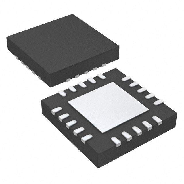
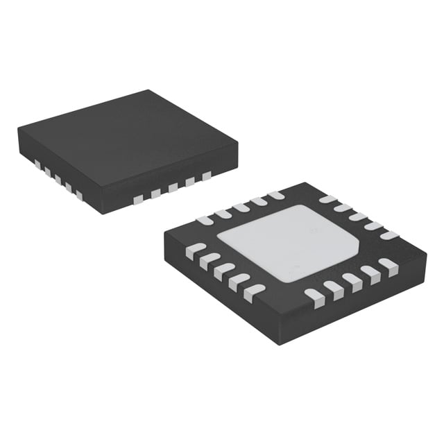
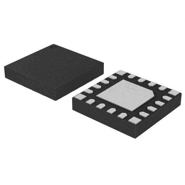
ICGOO电子元器件商城为您提供Si4330-B1-FM由Silicon Laboratories设计生产,在icgoo商城现货销售,并且可以通过原厂、代理商等渠道进行代购。 Si4330-B1-FM价格参考。Silicon LaboratoriesSi4330-B1-FM封装/规格:RF 接收器, EZRadioPRO® RF Receiver FSK,GFSK,OOK 240MHz ~ 960MHz -121dBm 256kbps PCB,表面贴装 20-QFN(4x4)。您可以下载Si4330-B1-FM参考资料、Datasheet数据手册功能说明书,资料中有Si4330-B1-FM 详细功能的应用电路图电压和使用方法及教程。
Silicon Labs 的 SI4330-B1-FM 是一款高性能、低功耗的射频(RF)接收器芯片,广泛应用于无线通信领域。其主要应用场景包括:

1. 无线传感器网络:适用于智能家居、环境监测、工业自动化等场景,用于接收来自传感器节点的无线信号,实现远程监控与数据采集。

2. 遥控与遥测设备:常用于遥控器、无人机遥控、远程控制系统中,接收控制指令,实现设备的无线操控。

3. 家庭自动化系统:如无线门铃、智能照明控制、安防系统等,SI4330-B1-FM 可靠的接收性能确保了系统的稳定运行。

4. AMR/AMI(自动抄表系统):用于水表、电表、燃气表等自动抄表系统中,接收计量设备发送的数据,便于远程管理和数据分析。

5. 消费类电子产品:如无线音频设备、玩具、遥控车等,适用于需要稳定接收无线信号的低成本、低功耗应用。

该芯片支持多种调制方式(如 FSK、GFSK、OOK),具备良好的灵敏度和抗干扰能力,适合在复杂电磁环境中使用。其小型封装和低功耗设计也使其非常适合电池供电设备。
| 参数 | 数值 |
| 产品目录 | |
| 描述 | IC RCVR ISM 960MHZ 3.6V 20-QFN射频接收器 Si4330 EZradioPRO Transceiver (rev B1) |
| 产品分类 | |
| 品牌 | Silicon LabsSilicon Laboratories Inc |
| 产品手册 | |
| 产品图片 |
|
| rohs | 符合RoHS无铅 / 符合限制有害物质指令(RoHS)规范要求 |
| 产品系列 | RF集成电路,射频接收器,Silicon Labs Si4330-B1-FMEZRadioPRO® |
| 数据手册 | |
| 产品型号 | Si4330-B1-FMSI4330-B1-FM |
| 产品目录页面 | |
| 产品种类 | 射频接收器 |
| 供应商器件封装 | 20-QFN(4x4) |
| 其它名称 | 336-1629-5 |
| 包装 | 管件 |
| 单位重量 | 43 mg |
| 商标 | Silicon Labs |
| 商标名 | EZRadioPRO |
| 天线连接器 | PCB,表面贴装 |
| 存储容量 | - |
| 安装风格 | SMD/SMT |
| 封装 | Tray |
| 封装/外壳 | 20-VFQFN 裸露焊盘 |
| 封装/箱体 | QFN-20 |
| 工作温度 | -40°C ~ 85°C |
| 工作电源电压 | 3 V |
| 工作频率 | 240 MHz to 960 MHz |
| 工厂包装数量 | 91 |
| 应用 | 遥控,RKE,安全系统 |
| 数据接口 | PCB,表面贴装 |
| 数据速率(最大值) | 256 kbps |
| 最大工作温度 | + 85 C |
| 最小工作温度 | - 40 C |
| 标准包装 | 75 |
| 灵敏度 | -121dBm |
| 特性 | 配有 RSSI |
| 电压-电源 | 1.8 V ~ 3.6 V |
| 电流-接收 | 18.5mA |
| 电源电流 | 18.5 mA |
| 类型 | ISM Receiver |
| 系列 | Si4330 |
| 调制或协议 | FSK,GFSK,OOK |
| 频率 | 240MHz ~ 960MHz |


- 商务部:美国ITC正式对集成电路等产品启动337调查
- 曝三星4nm工艺存在良率问题 高通将骁龙8 Gen1或转产台积电
- 太阳诱电将投资9.5亿元在常州建新厂生产MLCC 预计2023年完工
- 英特尔发布欧洲新工厂建设计划 深化IDM 2.0 战略
- 台积电先进制程称霸业界 有大客户加持明年业绩稳了
- 达到5530亿美元!SIA预计今年全球半导体销售额将创下新高
- 英特尔拟将自动驾驶子公司Mobileye上市 估值或超500亿美元
- 三星加码芯片和SET,合并消费电子和移动部门,撤换高东真等 CEO
- 三星电子宣布重大人事变动 还合并消费电子和移动部门
- 海关总署:前11个月进口集成电路产品价值2.52万亿元 增长14.8%


PDF Datasheet 数据手册内容提取
Si4330-B1 Si4330 ISM RECEIVER Features Frequency Range = 240–960MHz Programmable GPIOs Sensitivity =–121dBm Embedded antenna diversity Low Power Consumption algorithm 18.5mA receive Configurable packet handler Data Rate = 0.123 to 256kbps Preamble detector FSK, GFSK, and OOK modulation RX 64 byte FIFO Power Supply = 1.8 to 3.6V Low battery detector Ultra low power shutdown mode Temperature sensor and 8-bit ADC Digital RSSI –40 to +85°C temperature range Wake-up timer Integrated voltage regulators Ordering Information: Auto-frequency calibration (AFC) Frequency hopping capability See page63. Clear channel assessment On-chip crystal tuning Programmable RX BW 2.6–620kHz 20-Pin QFN package Programmable packet handler Low BOM Pin Assignments Power-on-reset (POR) Si4330 Applications SDN XIN XOUT nIRQ nSEL Remote control Remote meter reading VDD_RF 1 20 19 18 17 16 Home security & alarm Remote keyless entry Telemetry Home automation NC 2 15 SCLK Personal data logging Industrial control RXp 3 GND 14 SDI Toy control Sensor networks RXn 4 PAD 13 SDO Tire pressure monitoring Health monitors Wireless PC peripherals Tag readers NC 5 12 VDD_DIG 6 7 8 9 10 11 NC Description 1 0 1 2 G NT O_ O_ O_ DI Silicon Laboratories’ Si4330 is a highly integrated, single chip wireless ISM A GPI GPI GPI VR_ receiver. The high-performance EZRadioPRO® family includes a complete line of transmitters, receivers, and transceivers allowing the RF system designer to Patents pending choose the optimal wireless part for their application. The Si4330 offers advanced radio features including continuous frequency coverage from 240–960MHz. The Si4330’s high level of integration offers reduced BOM cost while simplifying the overall system design. The extremely low receive sensitivity (–121dBm) ensures extended range and improved link performance. Built-in antenna diversity and support for frequency hopping can be used to further extend range and enhance performance. Additional system features such as an automatic wake-up timer, low battery detector, 64byte RX FIFO, automatic packet handling, and preamble detection reduce overall current consumption and allow the use of a lower-cost system MCU. An integrated temperature sensor, general purpose ADC, power-on-reset (POR), and GPIOs further reduce overall system cost and size. The Si4330’s digital receive architecture features a high-performance ADC and DSP based modem which performs demodulation, filtering, and packet handling for increased flexibility and performance. An easy-to-use calculator is provided to quickly configure the radio settings, simplifying customer's system design and reducing time to market. Rev 1.0 12/09 Copyright © 2009 by Silicon Laboratories Si4330
Si4330-B1 Functional Block Diagram 2 Preliminary Rev. 0.1
Si4330-B1 TABLE OF CONTENTS Section Page 1. Electrical Specifications . . . . . . . . . . . . . . . . . . . . . . . . . . . . . . . . . . . . . . . . . . . . . . . . . . .7 1.1. Definition of Test Conditions . . . . . . . . . . . . . . . . . . . . . . . . . . . . . . . . . . . . . . . . . . .13 2. Functional Description . . . . . . . . . . . . . . . . . . . . . . . . . . . . . . . . . . . . . . . . . . . . . . . . . . .14 2.1. Operating Modes . . . . . . . . . . . . . . . . . . . . . . . . . . . . . . . . . . . . . . . . . . . . . . . . . . . .15 3. Controller Interface . . . . . . . . . . . . . . . . . . . . . . . . . . . . . . . . . . . . . . . . . . . . . . . . . . . . . .16 3.1. Serial Peripheral Interface (SPI) . . . . . . . . . . . . . . . . . . . . . . . . . . . . . . . . . . . . . . . .16 3.2. Operating Mode Control . . . . . . . . . . . . . . . . . . . . . . . . . . . . . . . . . . . . . . . . . . . . . .18 3.3. Interrupts . . . . . . . . . . . . . . . . . . . . . . . . . . . . . . . . . . . . . . . . . . . . . . . . . . . . . . . . .21 3.4. System Timing . . . . . . . . . . . . . . . . . . . . . . . . . . . . . . . . . . . . . . . . . . . . . . . . . . . . .22 3.5. Frequency Control . . . . . . . . . . . . . . . . . . . . . . . . . . . . . . . . . . . . . . . . . . . . . . . . . . .23 4. Modulation Options . . . . . . . . . . . . . . . . . . . . . . . . . . . . . . . . . . . . . . . . . . . . . . . . . . . . . .28 4.1. FIFO Mode . . . . . . . . . . . . . . . . . . . . . . . . . . . . . . . . . . . . . . . . . . . . . . . . . . . . . . . .28 5. Internal Functional Blocks . . . . . . . . . . . . . . . . . . . . . . . . . . . . . . . . . . . . . . . . . . . . . . . .29 5.1. RX LNA . . . . . . . . . . . . . . . . . . . . . . . . . . . . . . . . . . . . . . . . . . . . . . . . . . . . . . . . . . .29 5.2. RX I-Q Mixer . . . . . . . . . . . . . . . . . . . . . . . . . . . . . . . . . . . . . . . . . . . . . . . . . . . . . . .29 5.3. Programmable Gain Amplifier . . . . . . . . . . . . . . . . . . . . . . . . . . . . . . . . . . . . . . . . . .29 5.4. ADC . . . . . . . . . . . . . . . . . . . . . . . . . . . . . . . . . . . . . . . . . . . . . . . . . . . . . . . . . . . . . .29 5.5. Digital Modem . . . . . . . . . . . . . . . . . . . . . . . . . . . . . . . . . . . . . . . . . . . . . . . . . . . . . .29 5.6. Synthesizer . . . . . . . . . . . . . . . . . . . . . . . . . . . . . . . . . . . . . . . . . . . . . . . . . . . . . . . .30 5.7. Crystal Oscillator . . . . . . . . . . . . . . . . . . . . . . . . . . . . . . . . . . . . . . . . . . . . . . . . . . . .31 5.8. Regulators . . . . . . . . . . . . . . . . . . . . . . . . . . . . . . . . . . . . . . . . . . . . . . . . . . . . . . . . .31 6. Data Handling and Packet Handler . . . . . . . . . . . . . . . . . . . . . . . . . . . . . . . . . . . . . . . . . .32 6.1. RX FIFO . . . . . . . . . . . . . . . . . . . . . . . . . . . . . . . . . . . . . . . . . . . . . . . . . . . . . . . . . .32 6.2. Packet Configuration . . . . . . . . . . . . . . . . . . . . . . . . . . . . . . . . . . . . . . . . . . . . . . . . .33 6.3. Packet Handler RX Mode . . . . . . . . . . . . . . . . . . . . . . . . . . . . . . . . . . . . . . . . . . . . .33 6.4. Data Whitening, Manchester Encoding, and CRC . . . . . . . . . . . . . . . . . . . . . . . . . .36 6.5. Preamble Detector . . . . . . . . . . . . . . . . . . . . . . . . . . . . . . . . . . . . . . . . . . . . . . . . . .36 6.6. Preamble Length . . . . . . . . . . . . . . . . . . . . . . . . . . . . . . . . . . . . . . . . . . . . . . . . . . . .37 6.7. Invalid Preamble Detector . . . . . . . . . . . . . . . . . . . . . . . . . . . . . . . . . . . . . . . . . . . . .37 6.8. Synchronization Word Configuration . . . . . . . . . . . . . . . . . . . . . . . . . . . . . . . . . . . . .37 6.9. Receive Header Check . . . . . . . . . . . . . . . . . . . . . . . . . . . . . . . . . . . . . . . . . . . . . . .38 7. RX Modem Configuration . . . . . . . . . . . . . . . . . . . . . . . . . . . . . . . . . . . . . . . . . . . . . . . . .39 7.1. Modem Settings for FSK and GFSK . . . . . . . . . . . . . . . . . . . . . . . . . . . . . . . . . . . . .39 8. Auxiliary Functions . . . . . . . . . . . . . . . . . . . . . . . . . . . . . . . . . . . . . . . . . . . . . . . . . . . . . .40 8.1. Smart Reset . . . . . . . . . . . . . . . . . . . . . . . . . . . . . . . . . . . . . . . . . . . . . . . . . . . . . . .40 8.2. Microcontroller Clock . . . . . . . . . . . . . . . . . . . . . . . . . . . . . . . . . . . . . . . . . . . . . . . . .41 8.3. General Purpose ADC . . . . . . . . . . . . . . . . . . . . . . . . . . . . . . . . . . . . . . . . . . . . . . .42 8.4. Temperature Sensor . . . . . . . . . . . . . . . . . . . . . . . . . . . . . . . . . . . . . . . . . . . . . . . . .43 8.5. Low Battery Detector . . . . . . . . . . . . . . . . . . . . . . . . . . . . . . . . . . . . . . . . . . . . . . . . .45 Preliminary Rev. 0.1 3
Si4330-B1 8.6. Wake-Up Timer and 32 kHz Clock Source . . . . . . . . . . . . . . . . . . . . . . . . . . . . . . . .46 8.7. Low Duty Cycle Mode . . . . . . . . . . . . . . . . . . . . . . . . . . . . . . . . . . . . . . . . . . . . . . . .48 8.8. GPIO Configuration . . . . . . . . . . . . . . . . . . . . . . . . . . . . . . . . . . . . . . . . . . . . . . . . . .49 8.9. Antenna Diversity . . . . . . . . . . . . . . . . . . . . . . . . . . . . . . . . . . . . . . . . . . . . . . . . . . .50 8.10. RSSI and Clear Channel Assessment . . . . . . . . . . . . . . . . . . . . . . . . . . . . . . . . . .51 9. Reference Design . . . . . . . . . . . . . . . . . . . . . . . . . . . . . . . . . . . . . . . . . . . . . . . . . . . . . . . .52 10. Application Notes and Reference Designs . . . . . . . . . . . . . . . . . . . . . . . . . . . . . . . . . .53 11. Customer Support . . . . . . . . . . . . . . . . . . . . . . . . . . . . . . . . . . . . . . . . . . . . . . . . . . . . . .53 12. Register Table and Descriptions . . . . . . . . . . . . . . . . . . . . . . . . . . . . . . . . . . . . . . . . . .54 13. Pin Descriptions: Si4330 . . . . . . . . . . . . . . . . . . . . . . . . . . . . . . . . . . . . . . . . . . . . . . . . .57 14. Ordering Information . . . . . . . . . . . . . . . . . . . . . . . . . . . . . . . . . . . . . . . . . . . . . . . . . . . .58 15. Package Markings (Top Marks) . . . . . . . . . . . . . . . . . . . . . . . . . . . . . . . . . . . . . . . . . . . .59 15.1. Si4330 Top Mark . . . . . . . . . . . . . . . . . . . . . . . . . . . . . . . . . . . . . . . . . . . . . . . . . . .59 15.2. Top Mark Explanation . . . . . . . . . . . . . . . . . . . . . . . . . . . . . . . . . . . . . . . . . . . . . . .59 16. Package Outline: Si4330 . . . . . . . . . . . . . . . . . . . . . . . . . . . . . . . . . . . . . . . . . . . . . . . . .60 17. PCB Land Pattern: Si4330 . . . . . . . . . . . . . . . . . . . . . . . . . . . . . . . . . . . . . . . . . . . . . . . .61 Document Change List . . . . . . . . . . . . . . . . . . . . . . . . . . . . . . . . . . . . . . . . . . . . . . . . . . . . .63 Contact Information . . . . . . . . . . . . . . . . . . . . . . . . . . . . . . . . . . . . . . . . . . . . . . . . . . . . . . . .64 4 Preliminary Rev. 0.1
Si4330-B1 LIST OF FIGURES Figure 1. RX Application Example............................................................................................ 14 Figure 2. SPI Timing..................................................................................................................16 Figure 3. SPI Timing—READ Mode..........................................................................................17 Figure 4. SPI Timing—Burst Write Mode..................................................................................17 Figure 5. SPI Timing—Burst Read Mode..................................................................................17 Figure 6. State Machine Diagram..............................................................................................18 Figure 7. RX Timing..................................................................................................................22 Figure 8. Sensitivity at 1% PER vs. Carrier Frequency Offset..................................................26 Figure 9. PLL Synthesizer Block Diagram.................................................................................30 Figure 10. FIFO Threshold........................................................................................................32 Figure 11. Packet Structure.......................................................................................................33 Figure 12. Required RX Packet Structure with Packet Handler Disabled.................................33 Figure 13. Multiple Packets in RX Packet Handler....................................................................34 Figure 14. Multiple Packets in RX with CRC or Header Error...................................................34 Figure 15. Operation of Data Whitening, Manchester Encoding, and CRC..............................36 Figure 16. Manchester Coding Example...................................................................................36 Figure 17. Header.....................................................................................................................38 Figure 18. POR Glitch Parameters............................................................................................40 Figure 19. General Purpose ADC Architecture.........................................................................42 Figure 20. Temperature Ranges using ADC8...........................................................................44 Figure 21. WUT Interrupt and WUT Operation..........................................................................47 Figure 22. Low Duty Cycle Mode..............................................................................................48 Figure 23. RSSI Value vs. Input Power.....................................................................................51 Figure 24. Receiver—Schematic Receiver—Top......................................................................52 Figure 25. 20-Pin Quad Flat No-Lead (QFN)............................................................................60 Figure 26. PCB Land Pattern....................................................................................................61 Preliminary Rev. 0.1 5
Si4330-B1 LIST OF TABLES Table 1. DC Characteristics1 ......................................................................................................7 Table 2. Synthesizer AC Electrical Characteristics1 ...................................................................8 Table 3. Receiver AC Electrical Characteristics1 .......................................................................9 Table 4. Auxiliary Block Specifications1 ...................................................................................10 Table 5. Digital IO Specifications (SDO, SDI, SCLK, nSEL, and nIRQ) ...................................11 Table 6. GPIO Specifications (GPIO_0, GPIO_1, and GPIO_2) ..............................................11 Table 7. Absolute Maximum Ratings ........................................................................................12 Table 8. Operating Modes ........................................................................................................15 Table 9. Serial Interface Timing Parameters ............................................................................16 Table 10. Operating Modes Response Time ............................................................................18 Table 11. Frequency Band Selection .......................................................................................24 Table 12. Packet Handler Registers .........................................................................................35 Table 13. Minimum Receiver Settling Time ..............................................................................37 Table 14. POR Parameters ......................................................................................................40 Table 15. Temperature Sensor Range .....................................................................................43 Table 16. Antenna Diversity Control .........................................................................................50 Table 17. Register Descriptions ...............................................................................................54 Table 18. Package Dimensions ................................................................................................60 Table 19. PCB Land Pattern Dimensions .................................................................................62 Preliminary Rev. 0.1 6
Si4330-B1 1. Electrical Specifications Table 1. DC Characteristics1 Parameter Symbol Conditions Min Typ Max Units Supply Voltage Range V 1.8 3.0 3.6 V DD Power Saving Modes I RC Oscillator, Main Digital Regulator, — 15 50 nA Shutdown and Low Power Digital Regulator OFF2 I Low Power Digital Regulator ON (Register values retained) — 450 800 nA Standby and Main Digital Regulator, and RC Oscillator OFF I RC Oscillator and Low Power Digital Regulator ON — 1 — µA Sleep (Register values retained) and Main Digital Regulator OFF I Main Digital Regulator and Low Battery Detector ON, — 1 — µA Sensor-LBD Crystal Oscillator and all other blocks OFF2 I Main Digital Regulator and Temperature Sensor ON, — 1 — µA Sensor-TS Crystal Oscillator and all other blocks OFF2 I Crystal Oscillator and Main Digital Regulator ON, — 800 — µA Ready all other blocks OFF. Crystal Oscillator buffer disabled TUNE Mode Current I Synthesizer and regulators enabled — 8.5 — mA Tune RX Mode Current I — 18.5 — mA RX Notes: 1. All specification guaranteed by production test unless otherwise noted. Production test conditions and max limits are listed in the "Production Test Conditions" section on page13. 2. Guaranteed by qualification. Qualification test conditions are listed in the "Production Test Conditions" section on page13. Preliminary Rev. 0.1 7
Si4330-B1 Table 2. Synthesizer AC Electrical Characteristics1 Parameter Symbol Conditions Min Typ Max Units Synthesizer Frequency F 240 — 960 MHz SYN Range Synthesizer Frequency F Low Band, 240–480MHz — 156.25 — Hz RES-LB Resolution2 F High Band, 480–960MHz — 312.5 — Hz RES-HB Reference Frequency f When using external reference signal 0.7 — 1.6 V REF_LV Input Level2 driving XOUT pin, instead of using crystal. Measured peak-to-peak (V ) PP Synthesizer Settling Time2 t Measured from exiting Ready mode with — 200 — µs LOCK XOSC running to any frequency. Including VCO calibration. Residual FM2 F Integrated over 250kHz bandwidth — 2 4 kHz RMS RMS (500Hz lower bound of integration) Phase Noise2 L(f ) F=10kHz — –80 — dBc/Hz M F=100kHz — –90 — dBc/Hz F=1MHz — –115 — dBc/Hz F=10MHz — –130 — dBc/Hz Notes: 1. All specification guaranteed by production test unless otherwise noted. Production test conditions and max limits are listed in the "Production Test Conditions" section on page13. 2. Guaranteed by qualification. Qualification test conditions are listed in the "Production Test Conditions" section on page13. 8 Preliminary Rev. 0.1
Si4330-B1 Table 3. Receiver AC Electrical Characteristics1 Parameter Symbol Conditions Min Typ Max Units RX Frequency F 240 — 960 MHz RX Range RX Sensitivity2 P (BER < 0.1%) — –121 — dBm RX_2 (2 kbps, GFSK, BT=0.5, f = 5kHz)3 P (BER < 0.1%) — –108 — dBm RX_40 (40 kbps, GFSK, BT=0.5, f = 20kHz)3 P (BER < 0.1%) — –104 — dBm RX_100 (100 kbps, GFSK, BT=0.5, f = 50kHz)3 P (BER < 0.1%) — –101 — dBm RX_125 (125 kbps, GFSK, BT=0.5, f = 62.5kHz) P (BER < 0.1%) — –110 — dBm RX_OOK (4.8kbps, 350kHz BW, OOK)3 (BER < 0.1%) — –102 — dBm (40kbps, 400kHz BW, OOK)3 RX Channel Bandwidth3 BW 2.6 — 620 kHz BER Variation vs Power P Up to +5dBm Input Level — 0 0.1 ppm RX_RES Level3 LNA Input Impedance3 R 915MHz — 51–60j — IN-RX (Unmatched—measured 868MHz — 54–63j — differentially across RX 433MHz — 89–110j — input pins) 315MHz — 107–137j — RSSI Resolution RES — ±0.5 — dB RSSI 1-Ch Offset Selectivity3 C/I Desired Ref Signal 3dB above sensitivity, — –31 — dB 1-CH 2-Ch Offset Selectivity3 C/I BER < 0.1%. Interferer and desired modu- — –35 — dB 2-CH lated with 40kbps F = 20kHz GFSK with 3-Ch Offset Selectivity3 C/I3-CH BT = 0.5, channel spacing = 150kHz — –40 — dB Blocking at 1MHz Offset3 1M Desired Ref Signal 3dB above sensitivity. — –52 — dB BLOCK Blocking at 4MHz Offset3 4M Interferer and desired modulated with — –56 — dB BLOCK 40kbps F = 20kHz GFSK with BT = 0.5 Blocking at 8MHz Offset3 8M — –63 — dB BLOCK Image Rejection3 Im Rejection at the image frequency. — –30 — dB REJ IF=937kHz Spurious Emissions3 P Measured at RX pins — — –54 dBm OB_RX1 Notes: 1. All specification guaranteed by production test unless otherwise noted. Production test conditions and max limits are listed in the "Production Test Conditions" section on page13. 2. Receive sensitivity at multiples of 30MHz may be degraded. If channels with a multiple of 30MHz are required it is recommended to shift the crystal frequency. Contact Silicon Labs Applications Support for recommendations. 3. Guaranteed by qualification. Qualification test conditions are listed in the "Production Test Conditions" section on page13. Preliminary Rev. 0.1 9
Si4330-B1 Table 4. Auxiliary Block Specifications1 Parameter Symbol Conditions Min Typ Max Units Temperature Sensor TS After calibrated via sensor offset — 0.5 — °C A Accuracy2 register tvoffs[7:0] Temperature Sensor TS — 5 — mV/°C S Sensitivity2 Low Battery Detector LBD — 50 — mV RES Resolution2 Low Battery Detector LBD — 250 — µs CT Conversion Time2 Microcontroller Clock F Configurable to 30MHz, 32.768K — 30M Hz MC Output Frequency 15MHz, 10MHz, 4MHz, 3MHz, 2MHz, 1MHz, or 32.768kHz General Purpose ADC Res- ADC — 8 — bit ENB olution2 General Purpose ADC Bit ADC — 4 — mV/bit RES Resolution2 Temp Sensor & General ADC — 305 — µs CT Purpose ADC Conversion Time2 30MHz XTAL Start-Up time t Using XTAL and board layout in — 600 — µs 30M reference design. Start-up time will vary with XTAL type and board layout. 30MHz XTAL Cap 30M — 97 — fF RES Resolution2 32kHz XTAL Start-Up Time2 t — 6 — sec 32k 32kHz XTAL Accuracy 32K Using 20ppm 32kHz Crystal — 100 — ppm RES using 32kHz XTAL2 32kHz Accuracy using 32KRC — 2500 — ppm RES Internal RC Oscillator2 POR Reset Time t — 16 — ms POR Software Reset Time2 t — 100 — µs soft Notes: 1. All specification guaranteed by production test unless otherwise noted. Production test conditions and max limits are listed in the "Production Test Conditions" section on page13. 2. Guaranteed by qualification. Qualification test conditions are listed in the "Production Test Conditions" section on page13. 10 Preliminary Rev. 0.1
Si4330-B1 Table 5. Digital IO Specifications (SDO, SDI, SCLK, nSEL, and nIRQ) Parameter Symbol Conditions Min Typ Max Units Rise Time T 0.1xV to 0.9xV , C = 5pF — — 8 ns RISE DD DD L Fall Time T 0.9xV to 0.1xV C = 5pF — — 8 ns FALL DD DD, L Input Capacitance C — — 1 pF IN Logic High Level Input Voltage V V –0.6 — — V IH DD Logic Low Level Input Voltage V — 0.6 V IL Input Current I 0<V < V –100 — 100 nA IN IN DD Logic High Level Output V I <1mA source, V =1.8V V –0.6 — — V OH OH DD DD Voltage Logic Low Level Output Voltage V I <1mA sink, V =1.8V — — 0.6 V OL OL DD Note: All specifications guaranteed by qualification. Qualification test conditions are listed in the "Production Test Conditions" section on page13. Table 6. GPIO Specifications (GPIO_0, GPIO_1, and GPIO_2) Parameter Symbol Conditions Min Typ Max Units Rise Time T 0.1xV to 0.9xV , — — 8 ns RISE DD DD C = 10pF, DRV<1:0>=HH L Fall Time T 0.9xV to 0.1xV — — 8 ns FALL DD DD, C = 10pF, DRV<1:0>=HH L Input Capacitance C — — 1 pF IN Logic High Level Input Voltage V V –0.6 — V IH DD Logic Low Level Input Voltage V — — 0.6 V IL Input Current I 0<V < V –100 — 100 nA IN IN DD Input Current If Pullup is Activated I V =0V 5 — 25 µA INP IL Maximum Output Current I DRV<1:0>=LL 0.1 0.5 0.8 mA OmaxLL I DRV<1:0>=LH 0.9 2.3 3.5 mA OmaxLH I DRV<1:0>=HL 1.5 3.1 4.8 mA OmaxHL I DRV<1:0>=HH 1.8 3.6 5.4 mA OmaxHH Logic High Level Output Voltage V I < I source, V –0.6 — — V OH OH Omax DD V =1.8V DD Logic Low Level Output Voltage V I < I sink, — — 0.6 V OL OL Omax V =1.8V DD Note: All specifications guaranteed by qualification. Qualification test conditions are listed in the "Production Test Conditions" section on page13. Preliminary Rev. 0.1 11
Si4330-B1 Table 7. Absolute Maximum Ratings Parameter Value Unit V to GND –0.3, +3.6 V DD Voltage on Digital Control Inputs –0.3, V + 0.3 V DD Voltage on Analog Inputs –0.3, V + 0.3 V DD RX Input Power +10 dBm Operating Ambient Temperature Range T –40 to +85 C A Thermal Impedance 30 C/W JA Junction Temperature T +125 C J Storage Temperature Range T –55 to +125 C STG Note: Stresses beyond those listed under “Absolute Maximum Ratings” may cause permanent damage to the device. These are stress ratings only and functional operation of the device at or beyond these ratings in the operational sections of the specifications is not implied. Exposure to absolute maximum rating conditions for extended periods may affect device reliability. Caution: ESD sensitive device. 12 Preliminary Rev. 0.1
Si4330-B1 1.1. Definition of Test Conditions Production Test Conditions: TA=+25°C VDD=+3.3VDC Sensitivity measured at 919MHz External reference signal (XOUT) = 1.0VPP at 30MHz, centered around 0.8VDC Production test schematic (unless noted otherwise) All RF input and output levels referred to the pins of the Si4330 (not the RF module) Extreme Test Conditions: TA = –40 to +85°C VDD = +1.8 to +3.6 VDC Using 4330-T-B1-B-xxx reference design or production test schematic All RF input levels referred to the pins of the Si4330 (not the RF module) Preliminary Rev. 0.1 13
Si4330-B1 2. Functional Description The Si4330 is an ISM wireless receiver with continuous frequency tuning over the specified bands which encompasses from 240–960MHz. The wide operating voltage range of 1.8–3.6V and low current consumption makes the Si4330 an ideal solution for battery powered applications. The Si4330 receiver uses a single-conversion mixer to downconvert the 2-level FSK/GFSK/OOK modulated receive signal to a low IF frequency. Following a programmable gain amplifier (PGA) the signal is converted to the digital domain by a high performance ADC allowing filtering, demodulation, slicing, and packet handling to be performed in the built-in DSP increasing the receiver’s performance and flexibility versus analog based architectures. The demodulated signal is then output to the system MCU through a programmable GPIO or via the standard SPI bus by reading the 64-byte RX FIFO. A high precision local oscillator (LO) is generated by an integrated VCO and Fractional-N PLL synthesizer. The synthesizer is designed to support configurable data rates, output frequency and frequency deviation at any frequency between 240–960MHz. The Si4330 supports frequency hopping and antenna diversity switch control to extend the link range and improve performance. Antenna diversity is completely integrated into the Si4330 and can improve the system link budget by 8–10dB, resulting in substantial range increases depending on the environmental conditions. The Si4330 is designed to work with a microcontroller, crystal, and a few external components to create a very low cost system. Voltage regulators are integrated on-chip which allows for a wide operating supply voltage range from +1.8 to +3.6V. A standard 4-pin SPI bus is used to communicate with an external microcontroller. Three configurable general purpose I/Os are available. A complete list of the available GPIO functions is shown in "8. Auxiliary Functions" on page 40 and includes microcontroller clock output, Antenna Diversity, Antenna Switch, POR, and various interrupts. A complete list of the available GPIO functions is shown in AN467: Si4330 Register Descriptions.” Supply Voltage C3 C4 C5 X1 VDD 30 MHz GP1 100 p 100 n 1 u GP2 SDN XIN XOUT nIRQ nSEL VDD_RF 20 19 18 17 16 SCLK GP3 1 15 C1 NC SDI GP4 2 14 RFp Si4330 SDO GP5 Microcontroller 3 13 L1 RXn VDD_D 4 12 NC 5 011 NC 6 7 8 9 1 C2 1 0 1 2G ANT GPIO GPIO GPIOR_DI C6 V 1 u VSS Programmable load capacitors for X1 are integrated. L1, C1, and C2 values depend on frequency band, and antenna impedance. Figure 1. RX Application Example 14 Preliminary Rev. 0.1
Si4330-B1 2.1. Operating Modes The Si4330 provides several operating modes which can be used to optimize the power consumption for a given application. Depending upon the system communication protocol, an optimal trade-off between the radio wake time and power consumption can be achieved. Table8 summarizes the operating modes of the Si4330. In general, any given operating mode may be classified as an active mode or a power saving mode. The table indicates which block(s) are enabled (active) in each corresponding mode. With the exception of the SHUTDOWN mode, all can be dynamically selected by sending the appropriate commands over the SPI operating mode. An “X” in any cell means that, in the given mode of operation, that block can be independently programmed to be either ON or OFF, without noticeably impacting the current consumption. The SPI circuit block includes the SPI interface hardware and the device register space. The 32kHz OSC block includes the 32.768kHz RC oscillator or 32.768kHz crystal oscillator and wake-up timer. AUX (Auxiliary Blocks) includes the temperature sensor, general purpose ADC, and low-battery detector. Table 8. Operating Modes Mode Name Circuit Blocks Digital LDO SPI 32kHz OSC AUX 30MHz PLL RX I VDD XTAL SHUTDOWN OFF OFF OFF OFF OFF OFF OFF 15nA (Register contents lost) STANDBY ON ON OFF OFF OFF OFF OFF 450nA (Register contents SLEEP ON ON X OFF OFF OFF 1µA retained) SENSOR ON X ON OFF OFF OFF 1µA READY ON X X ON OFF OFF 800µA TUNING ON X X ON ON OFF 8.5mA RECEIVE ON X X ON ON ON 18.5mA Preliminary Rev. 0.1 15
Si4330-B1 3. Controller Interface 3.1. Serial Peripheral Interface (SPI) The Si4330 communicates with the host MCU over a standard 3-wire SPI interface: SCLK, SDI, and nSEL. The host MCU can read data from the device on the SDO output pin. A SPI transaction is a 16-bit sequence which consists of a Read-Write (R/W) select bit, followed by a 7-bit address field (ADDR), and an 8-bit data field (DATA) as demonstrated in Figure2. The 7-bit address field is used to select one of the 128, 8-bit control registers. The R/W select bit determines whether the SPI transaction is a read or write transaction. If R/W=1 it signifies a WRITE transaction, while R/W=0 signifies a READ transaction. The contents (ADDR or DATA) are latched into the Si4330 every eight clock cycles. The timing parameters for the SPI interface are shown in Table9. The SCLK rate is flexible with a maximum rate of 10MHz. Address Data MSB LSB SDI RW A6 A5 A4 A3 A2 A1 A0 D7 D6 D5 D4 D3 D2 D1 D0 xx xx RW A7 SCLK nSEL Figure 2. SPI Timing Table 9. Serial Interface Timing Parameters Symbol Parameter Min (nsec) Diagram t Clock high time 40 CH t Clock low time 40 CL SCLK t Data setup time 20 DS t t t t t t t t SS CL CH DS DH DD SH DE t Data hold time 20 DH SDI t Output data delay time 20 DD SDO t Output enable time 20 EN tEN tSW t Output disable time 50 DE nSEL t Select setup time 20 SS t Select hold time 50 SH t Select high period 80 SW To read back data from the Si4330, the R/W bit must be set to 0 followed by the 7-bit address of the register from which to read. The 8 bit DATA field following the 7-bit ADDR field is ignored n the SDI pin when R/W=0. The next eight negative edge transitions of the SCLK signal will clock out the contents of the selected register. The data read from the selected register will be available on the SDO output pin. The READ function is shown in Figure3. After the READ function is completed the SDO pin will remain at either a logic 1 or logic 0 state depending on the last data bit clocked out (D0). When nSEL goes high the SDO output pin will be pulled high by internal pullup. 16 Preliminary Rev. 0.1
Si4330-B1 First Bit Last Bit RW D7 D6 D5 D4 D3 D2 D1 D0 SDI A6 A5 A4 A3 A2 A1 A0 =0 =X =X =X =X =X =X =X =X SCLK First Bit Last Bit SDO D7 D6 D5 D4 D3 D2 D1 D0 nSEL Figure3. SPI Timing—READ Mode The SPI interface contains a burst read/write mode which allows for reading/writing sequential registers without having to re-send the SPI address. When the nSEL bit is held low while continuing to send SCLK pulses, the SPI interface will automatically increment the ADDR and read from/write to the next address. An example burst write transaction is illustrated in Figure4 and a burst read in Figure5. As long as nSEL is held low, input data will be latched into the Si4330 every eight SCLK cycles. First Bit Last Bit RW D7 D6 D5 D4 D3 D2 D1 D0 D7 D6 D5 D4 D3 D2 D1 D0 SDI A6 A5 A4 A3 A2 A1 A0 =1 =X =X =X =X =X =X =X =X =X =X =X =X =X =X =X =X SCLK nSEL Figure 4. SPI Timing—Burst Write Mode First Bit Last Bit RW D7 D6 D5 D4 D3 D2 D1 D0 SDI A6 A5 A4 A3 A2 A1 A0 =0 =X =X =X =X =X =X =X =X SCLK First Bit SDO D7 D6 D5 D4 D3 D2 D1 D0 D7 D6 D5 D4 D3 D2 D1 D0 nSEL Figure5. SPI Timing—Burst Read Mode Preliminary Rev. 0.1 17
Si4330-B1 3.2. Operating Mode Control There are three primary states in the Si4330 radio state machine: SHUTDOWN, IDLE, and RX (see Figure6). The SHUTDOWN state completely shuts down the radio to minimize current consumption. There are five different configurations/options for the IDLE state which can be selected to optimize the chip to the applications needs. "Register 07h. Operating Mode and Function Control 1" controls which operating mode/state is selected with the exception of SHUTDOWN which is controlled by SDN pin20. The RX state may be reached automatically from any of the IDLE states by setting the rxon bit in "Register 07h. Operating Mode and Function Control 1". Table10 shows each of the operating modes with the time required to reach RX mode as well as the current consumption of each mode. The Si4330 includes a low-power digital regulated supply (LPLDO) which is internally connected in parallel to the output of the main digital regulator (and is available externally at the VR_DIG pin). This common digital supply voltage is connected to all digital circuit blocks including the digital modem, crystal oscillator, SPI, and register space. The LPLDO has extremely low quiescent current consumption but limited current supply capability; it is used only in the IDLE-STANDBY and IDLE-SLEEP modes. The main digital regulator is automatically enabled in all other modes. SSHHUUTTD DOWWNN IDLE* RX *Five Different Options for IDLE Figure 6. State Machine Diagram Table 10. Operating Modes Response Time State/Mode Response Time to RX Current in State /Mode [µA] Shut Down State 16.8ms 15nA Idle States: Standby Mode 800µs 450nA Sleep Mode 800µs 1µA Sensor Mode 800µs 1µA Ready Mode 200µs 800µA Tune Mode 200µs 8.5mA RX State NA 18.5mA 18 Preliminary Rev. 0.1
Si4330-B1 3.2.1. SHUTDOWN State The SHUTDOWN state is the lowest current consumption state of the device with nominally less than 15nA of current consumption. The SHUTDOWN state may be entered by driving the SDN pin (Pin 20) high. The SDN pin should be held low in all states except the SHUTDOWN state. In the SHUTDOWN state, the contents of the registers are lost and there is no SPI access. When the chip is connected to the power supply, a POR will be initiated after the falling edge of SDN. 3.2.2. IDLE State There are five different modes in the IDLE state which may be selected by "Register 07h. Operating Mode and Function Control 1". All modes have a tradeoff between current consumption and response time to RX mode. This tradeoff is shown in Table10. After the POR event, SWRESET, or exiting from the SHUTDOWN state the chip will default to the IDLE-READY mode. After a POR event the interrupt registers must be read to properly enter the SLEEP, SENSOR, or STANDBY mode and to control the 32kHz clock correctly. 3.2.2.1. STANDBY Mode STANDBY mode has the lowest current consumption of the five IDLE states with only the LPLDO enabled to maintain the register values. In this mode the registers can be accessed in both read and write mode. The STANDBY mode can be entered by writing 0h to "Register 07h. Operating Mode and Function Control 1". If an interrupt has occurred (i.e., the nIRQ pin = 0) the interrupt registers must be read to achieve the minimum current consumption. Additionally, the ADC should not be selected as an input to the GPIO in this mode as it will cause excess current consumption. 3.2.2.2. SLEEP Mode In SLEEP mode the LPLDO is enabled along with the Wake-Up-Timer, which can be used to accurately wake-up the radio at specified intervals. See "8.6. Wake-Up Timer and 32kHz Clock Source" on page 46 for more information on the Wake-Up-Timer. SLEEP mode is entered by setting enwt=1 (40h) in "Register 07h. Operating Mode and Function Control 1". If an interrupt has occurred (i.e., the nIRQ pin=0) the interrupt registers must be read to achieve the minimum current consumption. Also, the ADC should not be selected as an input to the GPIO in this mode as it will cause excess current consumption. 3.2.2.3. SENSOR Mode In SENSOR Mode either the Low Battery Detector, Temperature Sensor, or both may be enabled in addition to the LPLDO and Wake-Up-Timer. The Low Battery Detector can be enabled by setting enlbd=1 in "Register 07h. Operating Mode and Function Control 1". See "8.4. Temperature Sensor" on page 43 and "8.5. Low Battery Detector" on page 45 for more information on these features. If an interrupt has occurred (i.e., the nIRQ pin = 0) the interrupt registers must be read to achieve the minimum current consumption. 3.2.2.4. READY Mode READY Mode is designed to give a fast transition time to RX mode with reasonable current consumption. In this mode the Crystal oscillator remains enabled reducing the time required to switch to RX mode by eliminating the crystal start-up time. READY mode is entered by setting xton=1 in "Register 07h. Operating Mode and Function Control 1". To achieve the lowest current consumption state the crystal oscillator buffer should be disabled in “Register 62h. Crystal Oscillator Control and Test.” To exit ready mode, bufovr (bit 1) of this register must be set back to 0. 3.2.2.5. TUNE Mode In TUNE Mode the PLL remains enabled in addition to the other blocks enabled in the IDLE modes. This will give the fastest response to RX mode as the PLL will remain locked but it results in the highest current consumption. This mode of operation is designed for frequency hopping spread spectrum systems (FHSS). TUNE mode is entered by setting pllon = 1 in "Register 07h. Operating Mode and Function Control 1". It is not necessary to set xton to 1 for this mode, the internal state machine automatically enables the crystal oscillator. Preliminary Rev. 0.1 19
Si4330-B1 3.2.3. RX State The RX state may be entered from any of the IDLE modes when the rxon bit is set to 1 in "Register 07h. Operating Mode and Function Control 1". A built-in sequencer takes care of all the actions required to transition from one of the IDLE modes to the RX state. The following sequence of events will occur automatically to get the chip into RX mode when going from STANDBY mode to RX mode by setting the rxon bit: 1. Enable the main digital LDO and the Analog LDOs. 2. Start up crystal oscillator and wait until ready (controlled by an internal timer). 3. Enable PLL. 4. Calibrate VCO (this action is skipped when the vcocal bit is “0”, default value is “1”). 5. Wait until PLL settles to required receive frequency (controlled by an internal timer). 6. Enable receive circuits: LNA, mixers, and ADC. 7. Enable receive mode in the digital modem. Depending on the configuration of the radio all or some of the following functions will be performed automatically by the digital modem: AGC, AFC (optional), update status registers, bit synchronization, packet handling (optional) including sync word, header check, and CRC. 3.2.4. Device Status Add R/W Function/Description D7 D6 D5 D4 D3 D2 D1 D0 POR Def. 02 R Device Status ffovfl ffunfl rxffem headerr freqerr cps[1] cps[0] — The operational status of the chip can be read from "Register 02h. Device Status". 20 Preliminary Rev. 0.1
Si4330-B1 3.3. Interrupts The Si4330 is capable of generating an interrupt signal when certain events occur. The chip notifies the microcontroller that an interrupt event has occurred by setting the nIRQ output pin LOW = 0. This interrupt signal will be generated when any one (or more) of the interrupt events (corresponding to the Interrupt Status bits) shown below occur. The nIRQ pin will remain low until the microcontroller reads the Interrupt Status Register(s) (Registers 03h–04h) containing the active Interrupt Status bit. The nIRQ output signal will then be reset until the next change in status is detected. The interrupts must be enabled by the corresponding enable bit in the Interrupt Enable Registers (Registers 05h–06h). All enabled interrupt bits will be cleared when the microcontroller reads the interrupt status register. If the interrupt is not enabled when the event occurs it will not trigger the nIRQ pin, but the status may still be read at anytime in the Interrupt Status registers. AddR/W Function/Descript D7 D6 D5 D4 D3 D2 D1 D0 POR Def. ion 03 R Interrupt Status 1 ifferr Reserved Reserved irxffafull iext Reserved ipkvalid icrcerror — 04 R Interrupt Status 2 iswdet ipreaval ipreainval irssi iwut ilbd ichiprdy ipor — 05 R/W Interrupt Enable 1 enfferr Reserved Reserved enrxffafull enext Reserved enpkvalid encrcerror 00h 06 R/W Interrupt Enable 2 enswdet enpreaval enpreainval enrssi enwut enlbd enchiprdy enpor 01h For a complete descriptions of each interrupt, see “AN467: Si4330 Register Descriptions.” Preliminary Rev. 0.1 21
Si4330-B1 3.4. System Timing The system timing for RX mode is shown in Figure7. The user only needs to program the desired mode, and the internal sequencer will properly transition the part from its current mode. The VCO will automatically calibrate at every frequency change or power up. The PLL T0 time is to allow for bias settling of the VCO. The PLL TS time is for the settling time of the PLL, which has a default setting of 100µs. The total time for PLL T0, PLL CAL, and PLL TS under all conditions is 200µs. Under certain applications, the PLL T0 time and the PLL CAL may be skipped for faster turn-around time. Contact applications support if faster turnaround time is desired. L 0 A S XTALT iSmeettling PLL T LL C PLLT RX Packet P 600us s d s u e u 0 p 0 5 p 0 Default = ay be ski mmend 1 0-70us, 50us, M s, Reco ble 10u a 3 ur 0- g e Confi urabl g nfi o C Figure7. RX Timing 22 Preliminary Rev. 0.1
Si4330-B1 3.5. Frequency Control For calculating the necessary frequency register settings it is recommended that customers use Silicon Labs’ Wireless Design Suite (WDS) or the EZRadioPRO Register Calculator worksheet (in Microsoft Excel) available on the product website. These methods offer a simple method to quickly determine the correct settings based on the application requirements. The following information can be used to calculated these values manually. 3.5.1. Frequency Programming In order to receive an RF signal, the desired channel frequency, f , must be programmed into the Si4330. Note carrier that this frequency is the center frequency of the desired channel and not an LO frequency. The carrier frequency is generated by a Fractional-N Synthesizer, using 10MHz both as the reference frequency and the clock of the (3rd order) ∆Σ modulator. This modulator uses modulo 64000 accumulators. This design was made to obtain the desired frequency resolution of the synthesizer. The overall division ratio of the feedback loop consist of an integer part (N) and a fractional part (F). In a generic sense, the output frequency of the synthesizer is as follows: f 10MHz(N F) OUT The fractional part (F) is determined by three different values, Carrier Frequency (fc[15:0]), Frequency Offset (fo[8:0]), and Frequency Deviation (fd[7:0]). Due to the fine resolution and high loop bandwidth of the synthesizer, FSK modulation is applied inside the loop and is done by varying F according to the incoming data; this is discussed further in "3.5.4. Frequency Offset Adjustment" on page 26. Also, a fixed offset can be added to fine- tune the carrier frequency and counteract crystal tolerance errors. For simplicity assume that only the fc[15:0] register will determine the fractional component. The equation for selection of the carrier frequency is shown below: f 10MHz(hbsel1)(N F) carrier fc[15:0] f 10MHz*(hbsel1)*(fb[4:0]24 ) carrier 64000 Add R/W Function/Description D7 D6 D5 D4 D3 D2 D1 D0 POR Def. 73 R/W Frequency Offset 1 fo[7] fo[6] fo[5] fo[4] fo[3] fo[2] fo[1] fo[0] 00h 74 R/W Frequency Offset 2 Reserved Reserved Reserved Reserved Reserved Reserved fo[9] fo[8] 00h 75 R/W Frequency Band Select Reserved sbsel hbsel fb[4] fb[3] fb[2] fb[1] fb[0] 35h 76 R/W Nominal Carrier fc[15] fc[14] fc[13] fc[12] fc[11] fc[10] fc[9] fc[8] BBh Frequency 1 77 R/W Nominal Carrier fc[7] fc[6] fc[5] fc[4] fc[3] fc[2] fc[1] fc[0] 80h Frequency 0 The integer part (N) is determined by fb[4:0]. Additionally, the frequency can be halved by connecting a ÷2 divider to the output. This divider is not inside the loop and is controlled by the hbsel bit in "Register 75h. Frequency Band Select." This effectively partitions the entire 240–960MHz frequency range into two separate bands: High Band (HB) for hbsel=1, and Low Band (LB) for hbsel=0. The valid range of fb[4:0] is from 0 to 23. If a higher value is written into the register, it will default to a value of 23. The integer part has a fixed offset of 24 added to it as shown in the formula above. Table11 demonstrates the selection of fb[4:0] for the corresponding frequency band. After selection of the fb (N) the fractional component may be solved with the following equation: f fc[15:0] carrier fb[4:0]24*64000 10MHz*(hbsel 1) fb and fc are the actual numbers stored in the corresponding registers. Preliminary Rev. 0.1 23
Si4330-B1 Table 11. Frequency Band Selection fb[4:0] Value N Frequency Band hbsel=0 hbsel=1 0 24 240–249.9MHz 480–499.9MHz 1 25 250–259.9MHz 500–519.9MHz 2 26 260–269.9MHz 520–539.9MHz 3 27 270–279.9MHz 540–559.9MHz 4 28 280–289.9MHz 560–579.9MHz 5 29 290–299.9MHz 580–599.9MHz 6 30 300–309.9MHz 600–619.9MHz 7 31 310–319.9MHz 620–639.9MHz 8 32 320–329.9MHz 640–659.9MHz 9 33 330–339.9MHz 660–679.9MHz 10 34 340–349.9MHz 680–699.9MHz 11 35 350–359.9MHz 700–719.9MHz 12 36 360–369.9MHz 720–739.9MHz 13 37 370–379.9MHz 740–759.9MHz 14 38 380–389.9MHz 760–779.9MHz 15 39 390–399.9MHz 780–799.9MHz 16 40 400–409.9MHz 800–819.9MHz 17 41 410–419.9MHz 820–839.9MHz 18 42 420–429.9MHz 840–859.9MHz 19 43 430–439.9MHz 860–879.9MHz 20 44 440–449.9MHz 880–899.9MHz 21 45 450–459.9MHz 900–919.9MHz 22 46 460–469.9MHz 920–939.9MHz 23 47 470–479.9MHz 940–960MHz The chip will automatically shift the frequency of the Synthesizer down by 937.5kHz (30MHz ÷ 32) to achieve the correct Intermediate Frequency (IF) when RX mode is entered. Low-side injection is used in the RX Mixing architecture. 24 Preliminary Rev. 0.1
Si4330-B1 3.5.2. Easy Frequency Programming for FHSS While Registers 73h–77h may be used to program the carrier frequency of the Si4330, it is often easier to think in terms of “channels” or “channel numbers” rather than an absolute frequency value in Hz. Also, there may be some timing-critical applications (such as for Frequency Hopping Systems) in which it is desirable to change frequency by programming a single register. Once the channel step size is set, the frequency may be changed by a single register corresponding to the channel number. A nominal frequency is first set using Registers 73h–77h, as described above. Registers 79h and 7Ah are then used to set a channel step size and channel number, relative to the nominal setting. The Frequency Hopping Step Size (fhs[7:0]) is set in increments of 10kHz with a maximum channel step size of 2.56MHz. The Frequency Hopping Channel Select Register then selects channels based on multiples of the step size. F Fnom fhs[7:0](fhch[7:0]10kHz) carrier For example, if the nominal frequency is set to 900MHz using Registers 73h–77h, the channel step size is set to 1MHz using "Register 7Ah. Frequency Hopping Step Size," and "Register 79h. Frequency Hopping Channel Select" is set to 5d, the resulting carrier frequency would be 905MHz. Once the nominal frequency and channel step size are programmed in the registers, it is only necessary to program the fhch[7:0] register in order to change the frequency. Add R/W Function/Description D7 D6 D5 D4 D3 D2 D1 D0 POR Def. 79 R/W Frequency Hopping Channel fhch[7] fhch[6] fhch[5] fhch[4] fhch[3] fhch[2] fhch[1] fhch[0] 00h Select 7A R/W Frequency Hopping Step fhs[7] fhs[6] fhs[5] fhs[4] fhs[3] fhs[2] fhs[1] fhs[0] 00h Size 3.5.3. Automatic State Transition for Frequency Change If registers 79h or 7Ah are changed in RX mode, the state machine will automatically transition the chip back to TUNE and change the frequency. This feature is useful to reduce the number of SPI commands required in a Frequency Hopping System. This in turn reduces microcontroller activity, reducing current consumption. Preliminary Rev. 0.1 25
Si4330-B1 3.5.4. Frequency Offset Adjustment When the AFC is disabled the frequency offset can be adjusted manually by fo[9:0] in registers 73h and 74h. It is not possible to have both AFC and offset as internally they share the same register. The frequency offset adjustment and the AFC both are implemented by shifting the Synthesizer Local Oscillator frequency. This register is a signed register so in order to get a negative offset it is necessary to take the twos complement of the positive offset number. The offset can be calculated by the following: DesiredOffset 156.25Hz(hbsel1) fo[9:0] DesiredOffset fo[9:0] 156.25Hz(hbsel1) The adjustment range in high band is ±160kHz and in low band it is ±80kHz. For example to compute an offset of +50kHz in high band mode fo[9:0] should be set to 0A0h. For an offset of –50kHz in high band mode the fo[9:0] register should be set to 360h. Add R/W Function/Descripti D7 D6 D5 D4 D3 D2 D1 D0 POR on Def. 73 R/W Frequency Offset fo[7] fo[6] fo[5] fo[4] fo[3] fo[2] fo[1] fo[0] 00h 74 R/W Frequency Offset Reserved Reserved Reserved Reserved Reserved Reserved fo[9] fo[8] 00h 3.5.5. Automatic Frequency Control (AFC) All AFC settings can be easily obtained from the settings calculator. This is the recommended method to program all AFC settings. This section is intended to describe the operation of the AFC in more detail to help understand the trade-offs of using AFC. The receiver supports automatic frequency control (AFC) to compensate for frequency differences between the transmitter and receiver reference frequencies. These differences can be caused by the absolute accuracy and temperature dependencies of the reference crystals. Due to frequency offset compensation in the modem, the receiver is tolerant to frequency offsets up to 0.25 times the IF bandwidth when the AFC is disabled. When the AFC is enabled, the received signal will be centered in the pass-band of the IF filter, providing optimal sensitivity and selectivity over a wider range of frequency offsets up to 0.35 times the IF bandwidth. The trade-off of receiver sensitivity (at 1% PER) versus carrier offset and the impact of AFC are illustrated in Figure9. Figure8. Sensitivity at 1% PER vs. Carrier Frequency Offset 26 Preliminary Rev. 0.1
Si4330-B1 When AFC is enabled, the preamble length needs to be long enough to settle the AFC. In general, one byte of preamble is sufficient to settle the AFC. Disabling the AFC allows the preamble to be shortened from 40 bits to 32 bits. Note that with the AFC disabled, the preamble length must still be long enough to settle the receiver and to detect the preamble (see "6.6. Preamble Length" on page 37). The AFC corrects the detected frequency offset by changing the frequency of the Fractional-N PLL. When the preamble is detected, the AFC will freeze for the remainder of the packet. In multi-packet mode, the AFC is reset at the end of every packet and will re-acquire the frequency offset for the next packet. The AFC loop includes a bandwidth limiting mechanism improving the rejection of out of band signals. When the AFC loop is enabled, its pull-in-range is determined by the bandwidth limiter value (AFCLimiter) which is located in register 2Ah. AFC_pull_in_range=±AFCLimiter[7:0]x(hbsel+1)x625Hz The AFC Limiter register is an unsigned register and its value can be obtained from the EZRadioPRO Register Calculator spreadsheet. Frequency Correction AFC disabled Freq Offset Register AFC enabled AFC Preliminary Rev. 0.1 27
Si4330-B1 4. Modulation Options 4.1. FIFO Mode In FIFO mode, the receive data is stored in integrated FIFO register memory. The FIFOs are accessed via "Register 7Fh. FIFO Access," and are most efficiently accessed with burst read/write operation as discussed in "3.1. Serial Peripheral Interface (SPI)" on page 16. In RX mode, only the bytes of the received packet structure that are considered to be "data bytes" are stored in FIFO memory. Which bytes of the received packet are considered "data bytes" is determined by the Automatic Packet Handler (if enabled), in conjunction with the Packet Handler Registers (see Table12 on page35). If the Automatic Packet Handler is disabled, all bytes following the Sync word are considered data bytes and are stored in FIFO memory. Thus, even if Automatic Packet Handling operation is not desired, the preamble detection threshold and Sync word still need to be programmed so that the RX Modem knows when to start filling data into the FIFO. When the FIFO is being used in RX mode, all of the received data may still be observed directly (in real- time) by properly programming a GPIO pin as the RXDATA output pin; this can be quite useful during application development. When in FIFO mode, the chip will automatically exit the RX State when either the ipksent or ipkvalid interrupt occurs. The chip will return to any of the other states based on the settings in "Register 07h. Operating Mode and Function Control 1." In RX mode, the rxon bit will be cleared if ipkvalid occurs and the rxmpk bit (RX Multi-Packet bit, SPI Register 08h bit [4]) is not set. When the rxmpk bit is set, the part will not exit the RX state after successfully receiving a packet, but will remain in RX mode. The microcontroller will need to decide on the appropriate subsequent action, depending upon information such as an interrupt generated by CRC, packet valid, or preamble detect. 28 Preliminary Rev. 0.1
Si4330-B1 5. Internal Functional Blocks This section provides an overview some of the key blocks of the internal radio architecture. 5.1. RX LNA The input frequency range for the LNA is between 240–960MHz. The LNA provides gain with a noise figure low enough to suppress the noise of the following stages. The LNA has one step of gain control which is controlled by the analog gain control (AGC) algorithm. The AGC algorithm adjusts the gain of the LNA and PGA so the receiver can handle signal levels from sensitivity to +5dBm with optimal performance. 5.2. RX I-Q Mixer The output of the LNA is fed internally to the input of the receive mixer. The receive mixer is implemented as an I-Q mixer that provides both I and Q channel outputs to the programmable gain amplifier. The mixer consists of two double-balanced mixers whose RF inputs are driven in parallel, local oscillator (LO) inputs are driven in quadrature, and separate I and Q Intermediate Frequency (IF) outputs drive the programmable gain amplifier. The receive LO signal is supplied by an integrated VCO and PLL synthesizer operating between 240–960MHz. The necessary quadrature LO signals are derived from the divider at the VCO output. 5.3. Programmable Gain Amplifier The programmable gain amplifier (PGA) provides the necessary gain to boost the signal level into the dynamic range of the ADC. The PGA must also have enough gain switching to allow for large input signals to ensure a linear RSSI range up to –20dBm. The PGA has steps of 3dB which are controlled by the AGC algorithm in the digital modem. 5.4. ADC The amplified IQ IF signals are digitized using an Analog-to-Digital Converter (ADC), which allows for low current consumption and high dynamic range. The bandpass response of the ADC provides exceptional rejection of out of band blockers. 5.5. Digital Modem Using high-performance ADCs allows channel filtering, image rejection, and demodulation to be performed in the digital domain, resulting in reduced area while increasing flexibility. The digital modem performs the following functions: Channel selection filter RX demodulation AGC Preamble detector Invalid preamble detector Radio signal strength indicator (RSSI) Automatic frequency compensation (AFC) Packet handling including EZMacTM features Cyclic redundancy check (CRC) The digital channel filter and demodulator are optimized for ultra low power consumption and are highly configurable. Supported modulation types are GFSK, FSK, and OOK. The channel filter can be configured to support bandwidths ranging from 620kHz down to 2.6kHz. A large variety of data rates are supported ranging from 0.123 up to 256kbps. The AGC algorithm is implemented digitally using an advanced control loop optimized for fast response time. The configurable preamble detector is used to improve the reliability of the sync-word detection. The sync-word detector is only enabled when a valid preamble is detected, significantly reducing the probability of false detection. The received signal strength indicator (RSSI) provides a measure of the signal strength received on the tuned channel. The resolution of the RSSI is 0.5dB. This high resolution RSSI enables accurate channel power Preliminary Rev. 0.1 29
Si4330-B1 measurements for clear channel assessment (CCA), and carrier sense (CS) functionality. Frequency mistuning caused by crystal inaccuracies can be compensated by enabling the digital automatic frequency control (AFC) in receive mode. A comprehensive programmable packet handler including key features of Silicon Labs’ EZMacTM is integrated to create a variety of communication topologies ranging from peer-to-peer networks to mesh networks. The extensive programmability of the packet header allows for advanced packet filtering which in turn enables a mix of broadcast, group, and point-to-point communication. A wireless communication channel can be corrupted by noise and interference, and it is therefore important to know if the received data is free of errors. A cyclic redundancy check (CRC) is used to detect the presence of erroneous bits in each packet. A CRC is computed and appended at the end of each transmitted packet and verified by the receiver to confirm that no errors have occurred. The packet handler and CRC can significantly reduce the load on the system microcontroller allowing for a simpler and cheaper microcontroller. 5.6. Synthesizer An integrated Sigma Delta (Σ∆) Fractional-N PLL synthesizer capable of operating from 240–960MHz is provided on-chip. Using a Σ∆ synthesizer has many advantages; it provides flexibility in choosing data rate, deviation, channel frequency, and channel spacing. The PLL and - modulator scheme is designed to support any desired frequency and channel spacing in the range from 240–960MHz with a frequency resolution of 156.25Hz (Low band) or 312.5Hz (High band). Fref = 10 M Selectable PFD CP LPF RX Divider VCO N Figure 9. PLL Synthesizer Block Diagram The reference frequency to the PLL is 10MHz. The PLL utilizes a differential L-C VCO, with integrated on-chip inductors. The output of the VCO is followed by a configurable divider which will divide down the signal to the desired output frequency band. The modulus of the variable divide-by-N divider stage is controlled dynamically by the output from the - modulator. The tuning resolution is sufficient to tune to the commanded frequency with a maximum accuracy of 312.5Hz anywhere in the range between 240–960MHz. 5.6.1. VCO The output of the VCO is automatically divided down to the correct output frequency depending on the hbsel and fb[4:0] fields in "Register 75h. Frequency Band Select." In receive mode, the LO frequency is automatically shifted downwards by the IF frequency of 937.5kHz, allowing receive operation on the same frequency. The VCO integrates the resonator inductor and tuning varactor, so no external VCO components are required. The VCO uses a capacitance bank to cover the wide frequency range specified. The capacitance bank will automatically be calibrated every time the synthesizer is enabled. In certain fast hopping applications this might not be desirable so the VCO calibration may be skipped by setting the appropriate register. 30 Preliminary Rev. 0.1
Si4330-B1 5.7. Crystal Oscillator The Si4330 includes an integrated 30MHz crystal oscillator with a fast start-up time of less than 600µs when a suitable parallel resonant crystal is used. The design is differential with the required crystal load capacitance integrated on-chip to minimize the number of external components. By default, all that is required off-chip is the 30MHz crystal. The crystal load capacitance can be digitally programmed to accommodate crystals with various load capacitance requirements and to adjust the frequency of the crystal oscillator. The tuning of the crystal load capacitance is programmed through the xlc[6:0] field of "Register 09h. 30MHz Crystal Oscillator Load Capacitance." The total internal capacitance is 12.5pF and is adjustable in approximately 127 steps (97fF/step). The xtalshift bit provides a coarse shift in frequency but is not binary with xlc[6:0]. The crystal frequency adjustment can be used to compensate for crystal production tolerances. Utilizing the on- chip temperature sensor and suitable control software, the temperature dependency of the crystal can be canceled. The typical value of the total on-chip capacitance Cint can be calculated as follows: Cint = 1.8 pF + 0.085 pFxxlc[6:0] + 3.7 pFxxtalshift Note that the coarse shift bit xtalshift is not binary with xlc[6:0]. The total load capacitance Cload seen by the crystal can be calculated by adding the sum of all external parasitic PCB capacitances Cext to Cint. If the maximum value of Cint (16.3 pF) is not sufficient, an external capacitor can be added for exact tuning. Additional information on calculating Cext and crystal selection guidelines is provided in “AN417: Si4x3x Family Crystal Oscillator.” If AFC is disabled then the synthesizer frequency may be further adjusted by programming the Frequency Offset field fo[9:0]in "Register 73h. Frequency Offset 1" and "Register 74h. Frequency Offset 2", as discussed in "3.5. Frequency Control" on page 23. The crystal oscillator frequency is divided down internally and may be output to the microcontroller through one of the GPIO pins for use as the System Clock. In this fashion, only one crystal oscillator is required for the entire system and the BOM cost is reduced. The available clock frequencies and GPIO configuration are discussed further in "8.2. Microcontroller Clock" on page 41. The Si4330 may also be driven with an external 30MHz clock signal through the XOUT pin. When driving with an external reference or using a TCXO, the XTAL load capacitance register should be set to 0. Add R/W Function/Description D7 D6 D5 D4 D3 D2 D1 D0 POR Def. 09 R/W Crystal Oscillator Load xtalshift xlc[6] xlc[5] xlc[4] xlc[3] xlc[2] xlc[1] xlc[0] 7Fh Capacitance 5.8. Regulators There are a total of six regulators integrated onto the Si4330.With the exception of the digital regulator, all regulators are designed to operate with only internal decoupling. The digital regulator requires an external 1µF decoupling capacitor. All regulators are designed to operate with an input supply voltage from +1.8 to +3.6V. A supply voltage should only be connected to the VDD pins. No voltage should be forced on the digital regulator outputs. Preliminary Rev. 0.1 31
Si4330-B1 6. Data Handling and Packet Handler The internal modem is designed to operate with a packet including a 10101... preamble structure. To configure the modem to operate with packet formats without a preamble or other legacy packet structures contact customer support. 6.1. RX FIFO A 64 byte FIFO is integrated into the chip for RX, as shown in Figure11. "Register 7Fh. FIFO Access" is used to access the FIFO. A burst read, as described in "3.1. Serial Peripheral Interface (SPI)" on page 16, from address 7Fh will read data from the RX FIFO. RX FIFO RX FIFO Almost Full Threshold Figure 10. FIFO Threshold Add R/W Function/D D7 D6 D5 D4 D3 D2 D1 D0 POR Def. escription 08 R/W Operating & antdiv[2] antdiv[1] antdiv[0] rxmpk Reserved enldm ffclrrx Reserved 00h Function Control 2 The RX FIFO has one programmable threshold called the FIFO Almost Full Threshold, rxafthr[5:0]. When the incoming RX data crosses the Almost Full Threshold an interrupt will be generated to the microcontroller via the nIRQ pin. The microcontroller will then need to read the data from the RX FIFO. Add R/W Function/De D7 D6 D5 D4 D3 D2 D1 D0 POR scription Def. 7E R/W RX FIFO Reserved Reserved rxafthr[5] rxafthr[4] rxafthr[3] rxafthr[2] rxafthr[1] rxafthr[0] 37h Control The RX FIFO may be cleared or reset with the ffclrrx bit in “Register 08h. Operating Mode and Function Control 2,” on page 71. All interrupts may be enabled by setting the Interrupt Enabled bits in "Register 05h. Interrupt Enable 1" and “Register 06h. Interrupt Enable 2,” on page 69. If the interrupts are not enabled the function will not generate an interrupt on the nIRQ pin but the bits will still be read correctly in the Interrupt Status registers. 32 Preliminary Rev. 0.1
Si4330-B1 6.2. Packet Configuration When using the FIFO, automatic packet handling may be enabled for the RX mode. "Register 30h. Data Access Control" through “Register 39h. Synchronization Word 0,” on page 99 and “Register 3Fh. Check Header 3,” on page 100 through “Register 4Bh. Received Packet Length,” on page 104 control the configuration, status, and decoded RX packet data for Packet Handling. The general packet structure is shown in Figure12. The length of each field is shown below the field. The preamble pattern is always a series of alternating ones and zeroes, starting with a zero. All the fields have programmable lengths to accommodate different applications. The most common CRC polynominals are available for selection. h d gt Wor er en d L Preamble nc ea et Data CRC Sy H ck a P 1-512 Bytes 1-4 Bytes 0-4 Bytes or 1 Byte B0 yotre s2 0 Figure11. Packet Structure An overview of the packet handler configuration registers is shown in Table13. 6.3. Packet Handler RX Mode 6.3.1. Packet Handler Disabled When the packet handler is disabled certain fields in the received packet are still required. Proper modem operation requires preamble and sync when the FIFO is being used, as shown in Figure14. Bits after sync will be treated as raw data with no qualification. This mode allows for the creation of a custom packet handler when the automatic qualification parameters are not sufficient. Manchester encoding is supported but data whitening, CRC, and header checks are not Preamble SYNC DATA Figure 12.Required RX Packet Structure with Packet Handler Disabled 6.3.2. Packet Handler Enabled When the packet handler is enabled, all the fields of the packet structure need to be configured. The receive FIFO can be configured to handle packets of fixed or variable length with or without a header. If multiple packets are desired to be stored in the FIFO, then there are options available for the different fields that will be stored into the FIFO. Figure15 demonstrates the options and settings available when multiple packets are enabled. Figure16 demonstrates the operation of fixed packet length and correct/incorrect packets. Preliminary Rev. 0.1 33
Si4330-B1 Transmission: RX FIFO Contents: rx_multi_pk_en = 0 rx_multi_pk_en = 1 Register Header(s) txhdlen = 0 txhdlen > 0 Data fixpklen fixpklen Register Length 0 1 0 1 Data Data H FIFO H L L Data Data Data Data Data Figure 13. Multiple Packets in RX Packet Handler Initial state PK 1 OK PK 2 OK PK 3 PK 4 OK ERROR RX FIFO Addr. RX FIFO Addr. RX FIFO Addr. RX FIFO Addr. RX FIFO Addr. 0 Write 0 0 0 0 Pointer H H H H L L L L Data Data Data Data Write Pointer HL HL HL Data Write Data Write Data Pointer Pointer H H L L Data Data Write CRC Pointer error 63 63 63 63 63 Figure 14. Multiple Packets in RX with CRC or Header Error 34 Preliminary Rev. 0.1
Si4330-B1 Table 12. Packet Handler Registers Add R/W Function/Description D7 D6 D5 D4 D3 D2 D1 D0 POR Def. 30 R/W Data Access Control enpacrx lsbfrst crcdonly *Reserved Reserved encrc crc[1] crc[0] 1Dh 31 R EzMAC status Reserved rxcrc1 pksrch pkrx pkvalid crcerror Reserved Reserved — 32 R/W Header Control 1 bcen[3] enbcast[2] enbcast[1] enbcast[0] hdch[3] hdch[2] hdch[1] hdch[0] 0Ch 33 R/W Header Control 2 skipsyn hdlen[2] hdlen[1] hdlen[0] fixpklen synclen[1] synclen[0] prealen[8] 22h 34 R/W Preamble Length prealen[7] prealen[6] prealen[5] prealen[4] prealen[3] prealen[2] prealen[1] prealen[0] 07h 35 R/W Preamble Detection Control preath[4] preath[3] preath[2] preath[1] preath[0] Reserved Reserved Reserved 20h 36 R/W Sync Word 3 sync[31] sync[30] sync[29] sync[28] sync[27] sync[26] sync[25] sync[24] 2Dh 37 R/W Sync Word 2 sync[23] sync[22] sync[21] sync[20] sync[19] sync[18] sync[17] sync[16] D4h 38 R/W Sync Word 1 sync[15] sync[14] sync[13] sync[12] sync[11] sync[10] sync[9] sync[8] 00h 39 R/W Sync Word 0 sync[7] sync[6] sync[5] sync[4] sync[3] sync[2] sync[1] sync[0] 00h 3A–3E R/W Reserved Reserved 3F R/W Check Header 3 chhd[31] chhd[30] chhd[29] chhd[28] chhd[27] chhd[26] chhd[25] chhd[24] 00h 40 R/W Check Header 2 chhd[23] chhd[22] chhd[21] chhd[20] chhd[19] chhd[18] chhd[17] chhd[16] 00h 41 R/W Check Header 1 chhd[15] chhd[14] chhd[13] chhd[12] chhd[11] chhd[10] chhd[9] chhd[8] 00h 42 R/W Check Header 0 chhd[7] chhd[6] chhd[5] chhd[4] chhd[3] chhd[2] chhd[1] chhd[0] 00h 43 R/W Header Enable 3 hden[31] hden[30] hden[29] hden[28] hden[27] hden[26] hden[25] hden[24] FFh 44 R/W Header Enable 2 hden[23] hden[22] hden[21] hden[20] hden[19] hden[18] hden[17] hden[16] FFh 45 R/W Header Enable 1 hden[15] hden[14] hden[13] hden[12] hden[11] hden[10] hden[9] hden[8] FFh 46 R/W Header Enable 0 hden[7] hden[6] hden[5] hden[4] hden[3] hden[2] hden[1] hden[0] FFh 47 R Received Header 3 rxhd[31] rxhd[30] rxhd[29] rxhd[28] rxhd[27] rxhd[26] rxhd[25] rxhd[24] — 48 R Received Header 2 rxhd[23] rxhd[22] rxhd[21] rxhd[20] rxhd[19] rxhd[18] rxhd[17] rxhd[16] — 49 R Received Header 1 rxhd[15] rxhd[14] rxhd[13] rxhd[12] rxhd[11] rxhd[10] rxhd[9] rxhd[8] — 4A R Received Header 0 rxhd[7] rxhd[6] rxhd[5] rxhd[4] rxhd[3] rxhd[2] rxhd[1] rxhd[0] — 4B R Received Packet Length rxplen[7] rxplen[6] rxplen[5] rxplen[4] rxplen[3] rxplen[2] rxplen[1] rxplen[0] — Preliminary Rev. 0.1 35
Si4330-B1 6.4. Data Whitening, Manchester Encoding, and CRC Data whitening can be used to avoid extended sequences of 0s or 1s in the transmitted data stream to achieve a more uniform spectrum. When enabled, the payload data bits are XORed with a pseudorandom sequence output from the built-in PN9 generator. The generator is initialized at the beginning of the payload. The receiver recovers the original data by repeating this operation. Manchester encoding can be used to ensure a dc-free transmission and good synchronization properties. When Manchester encoding is used, the effective datarate is unchanged but the actual datarate (preamble length, etc.) is doubled due to the nature of the encoding. The effective datarate when using Manchester encoding is limited to 128kbps. The implementation of Manchester encoding is shown in Figure16. Data whitening and Manchester encoding can be selected with "Register 70h. Modulation Mode Control 1". The CRC is configured via "Register 30h. Data Access Control." Figure15 demonstrates the portions of the packet which have Manchester encoding, data whitening, and CRC applied. CRC can be applied to only the data portion of the packet or to the data, packet length and header fields. Figure16 provides an example of how the Manchester encoding is done and also the use of the Manchester invert (enmaniv) function. Manchester Whitening CRC CRC (Over data only) Header/ PK Preamble Sync Data CRC Address Length Figure15. Operation of Data Whitening, Manchester Encoding, and CRC Data before Manchester 1 1 1 1 1 1 1 1 0 0 0 1 0 Preamble = 0xFF First 4bits of the synch. word = 0x2 Data after Machester ( manppol = 1, enmaninv = 0) Data after Machester ( manppol = 1, enmaninv = 1) Data before Manchester 0 0 0 0 0 0 0 0 0 0 0 1 0 Preamble = 0x00 First 4bits of the synch. word = 0x2 Data after Machester ( manppol = 0, enmaninv = 0) Data after Machester ( manppol = 0, enmaninv = 1) Figure 16. Manchester Coding Example 6.5. Preamble Detector The Si4330 has integrated automatic preamble detection. The preamble length is configurable from 1–256 bytes using the prealen[7:0] field in "Register 33h. Header Control 2" and "Register 34h. Preamble Length," as described in “6.2. Packet Configuration.” The preamble detection threshold, preath[4:0] as set in "Register 35h. Preamble Detection Control 1", is in units of 4 bits. The preamble detector searches for a preamble pattern with a length of preath[4:0]. If a false preamble detect occurs, the receiver will continuing searching for the preamble when no sync word is detected. When a false preamble detect occurs, the receiver will continuing searching for the preamble when no sync word is detected. Once preamble is detected (false or real) then the part will then start searching for sync. If no sync occurs then a timeout will occur and the device will initiate search for preamble again. The timeout period is defined as the sync word length plus four bits and will start after a non-preamble pattern is recognized after a valid preamble detection. The preamble detector output may be programmed onto one of the GPIO or read in the interrupt status registers. 36 Preliminary Rev. 0.1
Si4330-B1 6.6. Preamble Length The preamble detection threshold determines the number of valid preamble bits the radio must receive to qualify a valid preamble. The preamble threshold should be adjusted depending on the nature of the application. The required preamble length threshold will depend on when receive mode is entered in relation to the start of the transmitted packet and the length of the transmit preamble. With a shorter than recommended preamble detection threshold the probability of false detection is directly related to how long the receiver operates on noise before the transmit preamble is received. False detection on noise may cause the actual packet to be missed. The preamble detection threshold is programmed in register 35h. For most applications with a preamble length longer than 32 bits the default value of 20 is recommended for the preamble detection threshold. A shorter Preamble Detection Threshold may be chosen if occasional false detections may be tolerated. When antenna diversity is enabled a 20- bit preamble detection threshold is recommended. When the receiver is synchronously enabled just before the start of the packet, a shorter preamble detection threshold may be used. Table13 demonstrates the recommended preamble detection threshold and preamble length for various modes. It is possible to use the Si4330 in a raw mode without the requirement for a 101010 preamble. Contact customer support for further details. Table 13. Minimum Receiver Settling Time Mode Approximate Recommended preamble Recommended preamble Receiver length with 8-bit length with 20-bit Settling Time detection threshold detection threshold (G)FSK AFC Disabled 1 byte 20 bits 32 bits (G)FSK AFC Enabled 2 byte 28 bits 40 bits (G)FSK AFC Disabled +Antenna Diver- 1 byte — 64 bits sity Enabled (G)FSK AFC Enabled +Antenna Diversity 2 byte — 8 byte Enabled OOK 2 byte 3 byte 4 byte OOK + Antenna Diversity Enabled 8 byte — 8 byte Note: The recommended preamble length and preamble detection threshold listed above are to achieve 0% PER. They may be shortened when occasional packet errors are tolerable. 6.7. Invalid Preamble Detector When scanning channels in a frequency hopping system it is desirable to determine if a channel is valid in the minimum amount of time. The preamble detector can output an invalid preamble detect signal which can be used to identify the channel as invalid. After a configurable time set in Register60h[7:4], an invalid preamble detect signal is asserted indicating an invalid channel. The period for evaluating the signal for invalid preamble is defined as (inv_pre_th[3:0]x4)xBit Rate Period. The preamble detect and invalid preamble detect signals are available in "Register 03h. Interrupt/Status 1" and “Register 04h. Interrupt/Status 2” on page 66. 6.8. Synchronization Word Configuration The synchronization word length for RX can be configured in Reg 33h, synclen[1:0]. The expected or transmitted sync word can be configured from 1 to 4 bytes as defined below: synclen[1:0] = 00—Expected Synchronization Word (sync word) 3. synclen[1:0] = 01—Expected Synchronization Word 3 first, followed by sync word 2. synclen[1:0] = 10—Expected Synchronization Word 3 first, followed by sync word 2, followed by sync word 1. synclen[1:0] = 1—Expected Synchronization Word 3 first, followed by sync word 2, followed by sync word 1, followed by sync word 0. The sync is transmitted or expected in the following sequence: sync 3sync 2sync 1sync 0. The sync word values can be programmed in Registers 36h–39h. After preamble detection, the part will search for sync for a fixed period of time. If a sync is not recognized in this period, a timeout will occur, and the search for preamble will be re- Preliminary Rev. 0.1 37
Si4330-B1 initiated. The timeout period after preamble detections is defined as the value programmed into the sync word length plus four additional bits. 6.9. Receive Header Check The header check is designed to support 1–4 bytes and broadcast headers. The header length needs to be set in register 33h, hdlen[2:0]. The headers to be checked need to be set in register 32h, hdch[3:0]. For instance, there can be four bytes of header in the packet structure but only one byte of the header is set to be checked (i.e., header 3). For the headers that are set to be checked, the expected value of the header should be programmed in chhd[31:0] in Registers 3F–42. The individual bits within the selected bytes to be checked can be enabled or disabled with the header enables, hden[31:0] in Registers 43–46. For example, if you want to check all bits in header 3 then hden[31:24] should be set to FF but if only the last 4 bits are desired to be checked then it should be set to 00001111 (0F). Broadcast headers can also be programmed by setting bcen[3:0] in Register 32h. For broadcast header check the value may be either “FFh” or the value stored in the Check Header register. A logic equivalent of the header check for Header 3 is shown in Figure17. A similar logic check will be done for Header 2, Header 1, and Header 0 if enabled. Example for Header 3 rxhd[31:24] BIT Equivalence WISE comparison hden[31:24] = BIT WISE chhd[31:24] bcen[3] header3_ok Equivalence comparison FFh = rxhd[31:24] hdch[3] Figure 17. Header 38 Preliminary Rev. 0.1
Si4330-B1 7. RX Modem Configuration A Microsoft Excel (WDS) parameter calculator or Wireless Development Suite (WDS) calculator is provided to determine the proper settings for the modem. The calculator can be found on www.silabs.com or on the CD provided with the demo kits. An application note is available to describe how to use the calculator and to provide advanced descriptions of the modem settings and calculations. 7.1. Modem Settings for FSK and GFSK The modem performs channel selection and demodulation in the digital domain. The channel filter bandwidth is configurable from 2.6 to 620kHz. The receiver channel bandwidth is set depending on the data rate and modulation index via registers 1C–25h. The modulation index is equal to 2 times the peak deviation divided by the data rate (Rb). When Manchester coding is disabled, the required channel filter bandwidth is calculated as BW = 2Fd + Rb where Fd is the frequency deviation and Rb is the data rate. Preliminary Rev. 0.1 39
Si4330-B1 8. Auxiliary Functions 8.1. Smart Reset The Si4330 contains an enhanced integrated SMART RESET or POR circuit. The POR circuit contains both a classic level threshold reset as well as a slope detector POR. This reset circuit was designed to produce a reliable reset signal under any circumstances. Reset will be initiated if any of the following conditions occur: Initial power on, VDD starts from gnd: reset is active till VDD reaches VRR (see table); When VDD decreases below VLD for any reason: reset is active till VDD reaches VRR; A software reset via “Register 08h. Operating Mode and Function Control 2,” on page 71: reset is active for time T SWRST On the rising edge of a VDD glitch when the supply voltage exceeds the following time functioned limit: VDD nom. VDD(t) reset limit: 0.4V+t*0.2V/ms 0.4V actual VDD(t) showing glitch Reset T P t t=0, reset: VDD starts to rise Vglitch>=0.4+t*0.2V/ms Figure 18. POR Glitch Parameters Table 14. POR Parameters Parameter Symbol Comment Min Typ Max Unit Release Reset Voltage VRR 0.85 1.3 1.75 V Power-On VDD Slope SVDD tested VDD slope region 0.03 300 V/ms Low VDD Limit VLD VLD<VRR is guaranteed 0.7 1 1.3 V Software Reset Pulse TSWRST 50 470 us Threshold Voltage VTSD 0.4 V Reference Slope k 0.2 V/ms VDD Glitch Reset Pulse TP Also occurs after SDN, and 5 16 40 ms initial power on The reset will initialize all registers to their default values. The reset signal is also available for output and use by the microcontroller by using the default setting for GPIO_0. The inverted reset signal is available by default on GPIO_1. 40 Preliminary Rev. 0.1
Si4330-B1 8.2. Microcontroller Clock The 30MHz crystal oscillator frequency is divided down internally and may be output to the microcontroller through GPIO2. This feature is useful to lower BOM cost by using only one crystal in the system. The system clock frequency is selectable from one of 8 options, as shown below. Except for the 32.768kHz option, all other frequencies are derived by dividing the crystal oscillator frequency. The 32.768kHz clock signal is derived from an internal RC oscillator or an external 32kHz crystal. The default setting for GPIO2 is to output the microcontroller clock signal with a frequency of 1MHz. Add R/W Function/Description D7 D6 D5 D4 D3 D2 D1 D0 POR Def. 0A R/W Microcontroller Output Clock clkt[1] clkt[0] enlfc mclk[2] mclk[1] mclk[0] 06h mclk[2:0] Clock Frequency 000 30MHz 001 15MHz 010 10MHz 011 4MHz 100 3MHz 101 2MHz 110 1MHz 111 32.768kHz If the microcontroller clock option is being used there may be the need of a system clock for the microcontroller while the Si4330 is in SLEEP mode. Since the crystal oscillator is disabled in SLEEP mode in order to save current, the low-power 32.768kHz clock can be automatically switched to become the microcontroller clock. This feature is called enable low frequency clock and is enabled by the enlfc bit in “Register0Ah. Microcontroller Output Clock." When enlfc = 1 and the chip is in SLEEP mode then the 32.768kHz clock will be provided to the microcontroller as the system clock, regardless of the setting of mclk[2:0]. For example, if mclk[2:0] = 000, 30MHz will be provided through the GPIO output pin to the microcontroller as the system clock in all IDLE or RX states. When the chip enters SLEEP mode, the system clock will automatically switch to 32.768kHz from the RC oscillator or 32.768 XTAL. Another available feature for the microcontroller clock is the clock tail, clkt[1:0] in “Register0Ah. Microcontroller Output Clock." If the low frequency clock feature is not enabled (enlfc = 0), then the system clock to the microcontroller is disabled in SLEEP mode. However, it may be useful to provide a few extra cycles for the microcontroller to complete its operation prior to the shutdown of the system clock signal. Setting the clkt[1:0] field will provide additional cycles of the system clock before it shuts off. clkt[1:0] Clock Tail 00 0 cycles 01 128 cycles 10 256 cycles 11 512 cycles If an interrupt is triggered, the microcontroller clock will remain enabled regardless of the selected mode. As soon as the interrupt is read the state machine will then move to the selected mode. The minimum current consumption will not be achieved until the interrupt is read. For instance, if the chip is commanded to SLEEP mode but an interrupt has occurred the 30MHz XTAL will not be disabled until the interrupt has been cleared. Preliminary Rev. 0.1 41
Si4330-B1 8.3. General Purpose ADC An 8-bit SAR ADC is integrated for general purpose use, as well as for digitizing the on-chip temperature sensor reading. Registers 0Fh "ADC Configuration", 10h "Sensor Offset" and 4Fh "Amplifier Offset" can be used to configure the ADC operation. Every time an ADC conversion is desired, bit 7 "adcstart/adcbusy" in “Register 1Fh. Clock Recovery Gearshift Override” must be set to 1. This is a self clearing bit that will be reset to 0 at the end of the conversion cycle of the ADC. The conversion time for the ADC is 350µs. After this time or when the "adcstart/adcbusy" bit is cleared, then the ADC value may be read out of register 11h "ADC Value". The architecture of the ADC is shown in Figure19. The signal and reference inputs of the ADC are selected by adcsel[2:0] and adcref[1:0] in “Register 0Fh. ADC Configuration,” respectively. The default setting is to read out the temperature sensor using the bandgap voltage (VBG) as reference. With the VBG reference the input range of the ADC is from 0–1.02V with an LSB resolution of 4mV (1.02/255). Changing the ADC reference will change the LSB resolution accordingly. A differential multiplexer and amplifier are provided for interfacing external bridge sensors. The gain of the amplifier is selectable by adcgain[1:0] in Register 0Fh. The majority of sensor bridges have supply voltage (VDD) dependent gain and offset. The reference voltage of the ADC can be changed to either V /2 or V /3. A programmable V DD DD DD dependent offset voltage can be added using soffs[3:0] in register 10h. See “AN448: General Purpose ADC Configuration” for more details on the usage of the general purpose ADC. Diff. MUX Diff. Amp. …… …… Input MUX aoffs[4:0] soffs[3:0] adcsel[2:0] adcgain[1:0] GPIO0 GPIO1 …… GPIO2 8-bit ADC Temperature Sensor V in adc[7:0] adcsel[2:0] V ref 0 -1020mV / 0-255 Ref MUX VDD / 3 V / 2 DD …… VBG(1.2V) adcref[1:0] Figure19. General Purpose ADC Architecture Add R/W Function/Description D7 D6 D5 D4 D3 D2 D1 D0 POR Def. 0F R/W ADC Configuration adcstart/adcbusy adcsel[2] adcsel[1] adcsel[0] adcref[1] adcref[0] adcgain[1] adcgain[0] 00h 10 R/W Sensor Offset soffs[3] soffs[2] soffs[1] soffs[0] 00h 11 R ADC Value adc[7] adc[6] adc[5] adc[4] adc[3] adc[2] adc[1] adc[0] — 42 Preliminary Rev. 0.1
Si4330-B1 8.4. Temperature Sensor An integrated on-chip analog temperature sensor is available. The temperature sensor will be automatically enabled when the temperature sensor is selected as the input of the ADC or when the analog temp voltage is selected on the analog test bus. The temperature sensor value may be digitized using the general-purpose ADC and read out over the SPI through "Register 10h. ADC Sensor Amplifier Offset." The range of the temperature sensor is configurable. Table15 lists the settings for the different temperature ranges and performance. To use the Temp Sensor: 1. Set the input for ADC to the temperature sensor, "Register 0Fh. ADC Configuration"—adcsel[2:0]=000 2. Set the reference for ADC, "Register 0Fh. ADC Configuration"—adcref[1:0]=00 3. Set the temperature range for ADC, "Register 12h. Temperature Sensor Calibration"—tsrange[1:0] 4. Set entsoffs =1, "Register 12h. Temperature Sensor Calibration" 5. Trigger ADC reading, "Register 0Fh. ADC Configuration"—adcstart=1 6. Read temperature value—Read contents of "Register 11h. ADC Value" Add R/W Function/Description D7 D6 D5 D4 D3 D2 D1 D0 POR Def. 12 R/W Temperature tsrange[1] tsrange[0] entsoffs entstrim tstrim[3] tstrim[2] vbgtrim[1] vbgtrim[0] 20h Sensor Control 13 R/W Temperature Value Offset tvoffs[7] tvoffs[6] tvoffs[5] tvoffs[4] tvoffs[3] tvoffs[2] tvoffs[1] tvoffs[0] 00h Table 15. Temperature Sensor Range entoff tsrange[1] tsrange[0] Temp. range Unit Slope ADC8 LSB 1 0 0 –64 … 64 °C 8 mV/°C 0.5 °C 1 0 1 –64 … 192 °C 4 mV/°C 1 °C 1 1 0 0 … 128 °C 8 mV/°C 0.5 °C 1 1 1 –40 … 216 °F 4 mV/°F 1 °F 0* 1 0 0 … 341 °K 3 mV/°K 1.333 °K *Note: Absolute temperature mode, no temperature shift. This mode is only for test purposes. POR value of EN_TOFF is 1. The slope of the temperature sensor is very linear and monotonic. For absolute accuracy better than 10°C calibration is necessary. The temperature sensor may be calibrated by setting entsoffs=1 in “Register 12h. Temperature Sensor Control” and setting the offset with the tvoffs[7:0] bits in “Register 13h. Temperature Value Offset.” This method adds a positive offset digitally to the ADC value that is read in “Register 11h. ADC Value.” The other method of calibration is to use the tstrim which compensates the analog circuit. This is done by setting entstrim = 1 and using the tstrim[2:0] bits to offset the temperature in “Register 12h. Temperature Sensor Control.” With this method of calibration, a negative offset may be achieved. With both methods of calibration better than ±3°C absolute accuracy may be achieved. The different ranges for the temperature sensor and ADC8 are demonstrated in Figure20. The value of the ADC8 may be translated to a temperature reading by ADC8ValuexADC8 LSB + Lowest Temperature in Temp Range. For instance for a tsrange=00, Temp = ADC8Valuex0.5 – 64. Preliminary Rev. 0.1 43
Si4330-B1 Temperature Measurement with ADC8 300 250 200 Sensor Range 0 e u al Sensor Range 1 V 150 C Sensor Range 2 D A Sensor Range 3 100 50 0 -40 -20 0 20 40 60 80 100 Temperature [Celsius] Figure20. Temperature Ranges using ADC8 44 Preliminary Rev. 0.1
Si4330-B1 8.5. Low Battery Detector A low battery detector (LBD) with digital read-out is integrated into the chip. A digital threshold may be programmed into the lbdt[4:0] field in "Register 1Ah. Low Battery Detector Threshold." When the digitized battery voltage reaches this threshold an interrupt will be generated on the nIRQ pin to the microcontroller. The microcontroller can confirm source of the interrupt by reading "Register 03h. Interrupt/Status 1" and “Register 04h. Interrupt/Status 2,” on page 66. If the LBD is enabled while the chip is in SLEEP mode, it will automatically enable the RC oscillator which will periodically turn on the LBD circuit to measure the battery voltage. The battery voltage may also be read out through "Register 1Bh. Battery Voltage Level" at any time when the LBD is enabled. The low battery detect function is enabled by setting enlbd=1 in "Register 07h. Operating Mode and Function Control 1". Ad R/W Function/Description D7 D6 D5 D4 D3 D2 D1 D0 POR Def. 1A R/W Low Battery Detector Threshold lbdt[4] lbdt[3] lbdt[2] lbdt[1] lbdt[0] 14h 1B R Battery Voltage Level 0 0 0 vbat[4] vbat[3] vbat[2] vbat[1] vbat[0] — The LBD output is digitized by a 5-bit ADC. When the LBD function is enabled, enlbd=1 in "Register 07h. Operating Mode and Function Control 1", the battery voltage may be read at anytime by reading "Register 1Bh. Battery Voltage Level." A battery voltage threshold may be programmed in “Register 1Ah. Low Battery Detector Threshold." When the battery voltage level drops below the battery voltage threshold an interrupt will be generated on the nIRQ pin to the microcontroller if the LBD interrupt is enabled in “Register 06h. Interrupt Enable 2,” on page 69. The microcontroller will then need to verify the interrupt by reading the interrupt status register, addresses 03 and 04h. The LSB step size for the LBD ADC is 50mV, with the ADC range demonstrated in the table below. If the LBD is enabled the LBD and ADC will automatically be enabled every 1s for approximately 250µs to measure the voltage which minimizes the current consumption in Sensor mode. Before an interrupt is activated four consecutive readings are required. BatteryVoltage1.750mVADCValue ADC Value VDD Voltage [V] 0 < 1.7 1 1.7–1.75 2 1.75–1.8 … … 29 3.1–3.15 30 3.15–3.2 31 > 3.2 Preliminary Rev. 0.1 45
Si4330-B1 8.6. Wake-Up Timer and 32 kHz Clock Source The chip contains an integrated wake-up timer which can be used to periodically wake the chip from SLEEP mode. The wake-up timer runs from the internal 32.768kHz RC Oscillator. The wake-up timer can be configured to run when in SLEEP mode. If enwt=1 in "Register 07h. Operating Mode and Function Control 1" when entering SLEEP mode, the wake-up timer will count for a time specified defined in Registers 14–16h, "Wake Up Timer Period". At the expiration of this period an interrupt will be generated on the nIRQ pin if this interrupt is enabled. The microcontroller will then need to verify the interrupt by reading the Registers 03h–04h, "Interrupt Status 1 & 2". The wake-up timer value may be read at any time by the wtv[15:0] read only registers 13h–14h. The formula for calculating the Wake-Up Period is the following: 4M 2R WUT ms 32.768 WUT Register Description wtr[3:0] R Value in Formula wtd[1:0] D Value in Formula wtm[15:0] M Value in Formula Use of the D variable in the formula is only necessary if finer resolution is required than can be achieved by using the R value. Add R/W Function/Description D7 D6 D5 D4 D3 D2 D1 D0 POR Def. 14 R/W Wake-Up Timer Period 1 wtr[3] wtr[2] wtr[1] wtr[0] wtd[1] wtd[0] 00h 15 R/W Wake-Up Timer Period 2 wtm[15] wtm[14] wtm[13] wtm[12] wtm[11] wtm[10] wtm[9] wtm[8] 00h 16 R/W Wake-Up Timer Period 3 wtm[7] wtm[6] wtm[5] wtm[4] wtm[3] wtm[2] wtm[1] wtm[0] 00h 17 R Wake-Up Timer Value 1 wtv[15] wtv[14] wtv[13] wtv[12] wtv[11] wtv[10] wtv[9] wtv[8] — 18 R Wake-Up Timer Value 2 wtv[7] wtv[6] wtv[5] wtv[4] wtv[3] wtv[2] wtv[1] wtv[0] — There are two different methods for utilizing the wake-up timer (WUT) depending on if the WUT interrupt is enabled in “Register 06h. Interrupt Enable 2,” on page 69. If the WUT interrupt is enabled then nIRQ pin will go low when the timer expires. The chip will also change state so that the 30MHz XTAL is enabled so that the microcontroller clock output is available for the microcontroller to use to process the interrupt. The other method of use is to not enable the WUT interrupt and use the WUT GPIO setting. In this mode of operation the chip will not change state until commanded by the microcontroller. The different modes of operating the WUT and the current consumption impacts are demonstrated in Figure21. A 32kHz XTAL may also be used for better timing accuracy. By setting the x32ksel bit in “Register 07h. Operating & Function Control 1," GPIO0 is automatically reconfigured so that an external 32kHz XTAL may be connected to this pin. In this mode, the GPIO0 is extremely sensitive to parasitic capacitance, so only the XTAL should be connected to this pin with the XTAL physically located as close to the pin as possible. Once the x32ksel bit is set, all internal functions such as WUT, micro-controller clock, and LDC mode will use the 32kHz XTAL and not the 32kHz RC oscillator. 46 Preliminary Rev. 0.1
Si4330-B1 Interrupt Enable enwut =1 (Reg 06h) WUT Period GPIOX=00001 nIRQ SPI Interrupt Read Chip State Sleep Ready Sleep Ready Sleep Ready Sleep 1.5mA 1.5 mA 1.5 mA Current Consumption 1 uA 1 uA 1 uA Interrupt Enable enwut=0 (Reg 06h) WUT Period GPIOX =00001 nIRQ SPI Interrupt Read Chip State Sleep Current Consumption 1 uA Figure 21. WUT Interrupt and WUT Operation Preliminary Rev. 0.1 47
Si4330-B1 8.7. Low Duty Cycle Mode The Low Duty Cycle Mode is available to automatically wake-up the receiver to check if a valid signal is available. The basic operation of the low duty cycle mode is demonstrated in the figure below. If a valid preamble or sync word is not detected the chip will return to sleep mode until the beginning of a new WUT period. If a valid preamble and sync are detected the receiver on period will be extended for the low duty cycle mode duration (TLDC) to receive all of the packet. The WUT period must be set in conjunction with the low duty cycle mode duration. The R value (Reg 14h) is shared between the WUT and the TLDC. The ldc[7:0] bits are located in “Register 19h. Low Duty Cycle Mode Duration.” The time of the TLDC is determined by the formula below: 4 2 R TLDC ldc [7 : 0] ms 32 .768 Figure22. Low Duty Cycle Mode 48 Preliminary Rev. 0.1
Si4330-B1 8.8. GPIO Configuration Three general purpose IOs (GPIOs) are available. Numerous functions such as specific interrupts, Antenna Diversity Switch control, Microcontroller Output, etc. can be routed to the GPIO pins as shown in the tables below. When in Shutdown mode all the GPIO pads are pulled low. Note: The ADC should not be selected as an input to the GPIO in Standby or Sleep Modes and will cause excess current con- sumption. Add R/W Function/Des D7 D6 D5 D4 D3 D2 D1 D0 POR Def. cription 0B R/W GPIO0 gpio0drv[1] gpio0drv[0] pup0 gpio0[4] gpio0[3] gpio0[2] gpio0[1] gpio0[0] 00h Configuration 0C R/W GPIO1 gpio1drv[1] gpio1drv[0] pup1 gpio1[4] gpio1[3] gpio1[2] gpio1[1] gpio1[0] 00h Configuration 0D R/W GPIO2 gpio2drv[1] gpio2drv[0] pup2 gpio2[4] gpio2[3] gpio2[2] gpio2[1] gpio2[0] 00h Configuration 0E R/W I/O Port extitst[2] extitst[1] extitst[0] itsdo dio2 dio1 dio0 00h Configuration The GPIO settings for GPIO1 and GPIO2 are the same as for GPIO0 with the exception of the 00000 default setting. The default settings for each GPIO are listed below: GPIO 00000—Default Setting GPIO0 POR GPIO1 POR Inverted GPIO2 Microcontroller Clock This application uses antenna diversity so a GPIO is used to control the antenna switch. For a complete list of the available GPIO's see “AN4670: Si4330 Register Descriptions.” The GPIO drive strength may be adjusted with the gpioXdrv[1:0] bits. Setting a higher value will increase the drive strength and current capability of the GPIO by changing the driver size. Special care should be taken in setting the drive strength and loading on GPIO2 when the microcontroller clock is used. Excess loading or inadequate drive may contribute to increased spurious emissions. Preliminary Rev. 0.1 49
Si4330-B1 8.9. Antenna Diversity To mitigate the problem of frequency-selective fading due to multi-path propagation, some radio systems use a scheme known as antenna diversity. In this scheme, two antennas are used. Each time the radio enters RX mode the receive signal strength from each antenna is evaluated. This evaluation process takes place during the preamble portion of the packet. The antenna with the strongest received signal is then used for the remainder of that RX packet. This chip fully supports antenna diversity with an integrated antenna diversity control algorithm. The required signals needed to control an external SPDT RF switch (such as PIN diode or GaAs switch) are available on the GPIOx pins. The operation of these GPIO signals is programmable to allow for different antenna diversity architectures and configurations. The antdiv[2:0] bits are found in register 08h “Operating & Function Control 2.” The GPIO pins are capable of sourcing up to 5mA of current, so it may be used directly to forward-bias a PIN diode if desired. The antenna diversity algorithm will automatically toggle back and forth between the antennas until the packet starts to arrive. The recommended preamble length for optimal antenna selection is 8bytes. A special antenna diversity algorithm (antdiv[2:0] = 110 or 111) is included that allows for shorter preamble lengths for beacon mode in TDMA-like systems where the arrival of the packet is synchronous to the receiver enable. The recommended preamble length to obtain optimal antenna selection for synchronous mode is 4 bytes. Add R/W Function/Description D7 D6 D5 D4 D3 D2 D1 D0 POR Def. 08 R/W Operating & Function antdiv[2] antdiv[1] antdiv[0] rxmpk Reserved enldm ffclrrx Reserved 00h Control 2 Table 16. Antenna Diversity Control antdiv[2:0] RX State Non RX State GPIO Ant1 GPIO Ant2 GPIO Ant1 GPIO Ant2 000 0 1 0 0 001 1 0 0 0 010 0 1 1 1 011 1 0 1 1 100 Antenna Diversity Algorithm 0 0 101 Antenna Diversity Algorithm 1 1 110 Antenna Diversity Algorithm in Beacon Mode 0 0 111 Antenna Diversity Algorithm in Beacon Mode 1 1 50 Preliminary Rev. 0.1
Si4330-B1 8.10. RSSI and Clear Channel Assessment Received signal strength indicator (RSSI) is an estimate of the signal strength in the channel to which the receiver is tuned. The RSSI value can be read from an 8-bit register with 0.5dB resolution per bit. Figure23 demonstrates the relationship between input power level and RSSI value.The absolute value of the RSSI will change slightly depending on the modem settings. The RSSI may be read at anytime, but an incorrect error may rarely occur. The RSSI value may be incorrect if read during the update period. The update period is approximately 10ns every 4Tb. For 10kbps, this would result in a 1 in 40,000 probability that the RSSI may be read incorrectly. This probability is extremely low, but to avoid this, one of the following options is recommended: majority polling, reading the RSSI value within 1Tb of the RSSI interrupt, or using the RSSI threshold described in the next paragraph for Clear Channel Assessment (CCA). Add R/W Function/Description D7 D6 D5 D4 D3 D2 D1 D0 POR Def. 26 R Received Signal Strength Indicator rssi[7] rssi[6] rssi[5] rssi[4] rssi[3] rssi[2] rssi[1] rssi[0] — 27 R/W RSSI Threshold for Clear Channel Indicator rssith[7] rssith[6] rssith[5] rssith[4] rssith[3] rssith[2] rssith[1] rssith[0] 00h For CCA, threshold is programmed into rssith[7:0] in "Register 27h. RSSI Threshold for Clear Channel Indicator." After the RSSI is evaluated in the preamble, a decision is made if the signal strength on this channel is above or below the threshold. If the signal strength is above the programmed threshold then the RSSI status bit, irssi, in "Register 04h. Interrupt/Status 2" will be set to 1. The RSSI status can also be routed to a GPIO line by configuring the GPIO configuration register to GPIOx[3:0]=1110. RSSI vs Input Power 250 200 150 SI S R 100 50 0 -120 -100 -80 -60 -40 -20 0 20 In Pow [dBm] Figure 23.RSSI Value vs. Input Power Preliminary Rev. 0.1 51
Si4330-B1 9. Reference Design Reference designs are available at www.silabs.com for many common applications which include recommended schematics, BOM, and layout. RX matching component values for different frequency bands can be found in “AN427: EZRadioPRO Si433x and Si443x RX LNA Matching.” 4 & 3 (cid:9)6 ’(cid:19)(cid:15))(cid:14)’, &(cid:12)8 (cid:12)(cid:6)(cid:6)(cid:19)(cid:31) &(cid:12)(cid:5) (cid:12)*(cid:31) (cid:30)((cid:16)(cid:3)5"(cid:3)/(cid:9)(cid:17)(cid:16)(cid:7) " " (cid:24) :(cid:12)(cid:5)(cid:12) (cid:28)(cid:2)(cid:28)(cid:7)(cid:28);(cid:12)(cid:4)(cid:5)(cid:6)#(cid:5)(cid:6)3(cid:26)$ (cid:30)((cid:16)(cid:3)’(cid:19)(cid:15))(cid:30)((cid:16)(cid:3)’(cid:19)(cid:15)) 8AB(cid:23)(cid:6)(cid:2) (cid:4)(cid:5)(cid:5)(cid:13)<(cid:8)(cid:27)(cid:24)(cid:11)(cid:12)(cid:12)(cid:12)(cid:12)(cid:21) !==:(cid:28)(cid:27)4" (cid:8)(cid:13)(cid:2)(cid:30)(cid:2) ==(cid:13)(cid:12)7(cid:8)(cid:31)(cid:2)&!@(cid:12)(cid:4)(cid:2)" (cid:12)(cid:5)(cid:2)"(cid:30)(cid:12)(cid:21)(cid:24)""<" ?(cid:12)(cid:12)=&(cid:5)(cid:6)(cid:12)(cid:21)<<<(cid:12)(cid:30)(cid:30)(cid:30)(cid:8)(cid:28) "=>>>>???#(cid:24)(cid:27) >(cid:6)8AB(cid:23)(cid:27)(cid:12) &(cid:12)(cid:21) (cid:12)(cid:6)(cid:6)((cid:31) ematic 4(cid:12) (cid:24)""<=&(cid:12)(cid:8)(cid:13)<>(cid:8)(cid:13)<==&(cid:21) Sch (cid:12)(cid:21)(cid:5)(cid:4)7 (cid:12) n &(cid:8) % g i s &(cid:12) (cid:5)(cid:5)((cid:31) % De e (cid:8)! ,2 c ((cid:31) (cid:19) n &(cid:21) (cid:12)(cid:6)(cid:6) % -(cid:15) re &(cid:5) (cid:12)(cid:6)(cid:6)(cid:19)(cid:31) (cid:30)(cid:18)(cid:14)(cid:7))’(cid:15), &(cid:8)(cid:21)(cid:8)(cid:13) (cid:2)3#9(cid:26) (cid:19)(cid:7)./(cid:9)0*(cid:9)(cid:19)(cid:17)1(cid:7) i4330 Refe *(cid:31) 7(cid:6) (cid:7)’ S &(cid:4) (cid:21)(cid:25)(cid:21) (cid:9), 4. (cid:24)"" ,(cid:3).(cid:3)(cid:9),(cid:7)-(cid:15)+ 1 RX matchingLRCR1CR2nH][pF][pF] 334.710274.712113.96.8113.36.8 Figure2 ’ B [ ,(cid:7)-(cid:9)(cid:7)(cid:14) Si4330 RevFreq. band[MHz] 434470868915 *) ’ (cid:18) + (cid:7) + (cid:9) * (cid:15)) (cid:10) (cid:7) (cid:16) (cid:19) (cid:9) (cid:19) ’ ( (cid:14) ’ & % 52 Preliminary Rev. 0.1
Si4330-B1 10. Application Notes and Reference Designs A comprehensive set of application notes and reference designs are available to assist with the development of a radio system. A partial list of applications notes is given below. For the complete list of application notes, latest reference designs and demos visit the Silicon Labs website. AN361: Wireless MBUS Implementation using EZRadioPRO Devices AN379: Antenna Diversity with EZRadioPRO AN414: EZRadioPRO Layout Design Guide AN415: EZRadioPRO Programming Guide AN417: Si4x3x Family Crystal Oscillators AN419: ARIB STD-T67 Narrow-Band 426/429 MHz Measured on the Si4431-A0 AN427: EZRadioPRO Si433x and Si443x RX LNA Matching AN429: Using the DC-DC Converter on the F9xx Series MCU for Single Battery Operation with the EZRadioPRO RF Devices AN432: RX BER Measurement on EZRadioPRO with a Looped PN Sequence AN435: Si4032/4432 PA Matching AN436: Si4031/4431 PA Matching AN437: 915MHz Measurement Results and FCC Compliance AN439: EZRadioPRO Quick Start Guide AN440: Si4430/31/32 Register Descriptions AN445: Si4431 RF Performance and ETSI Compliance Test Results AN448: General Purpose ADC Configuration AN453: Using the EZRadioPRO Calculator and Advanced RX BW Calculations and Settings AN459: 950MHz Measurement Results and ARIB Compliance AN460: 470MHz Measurement Results for China AN461:+24dBm External PA Application Note and Reference Design AN462: Extended battery life using the EZRadioPRO and a DC-DC Buck Converter AN463: Support for Non-Standard Packet Structures and RAW Mode AN466: Si4030/31/32 Register Descriptions AN467: Si4330 Register Descriptions 11. Customer Support Technical support for the complete family of Silicon Labs wireless products is available by accessing the wireless section of the Silicon Labs' website at www.silabs.com\wireless. For answers to common questions please visit the wireless knowledge base at www.silabs.com/support/knowledgebase. Preliminary Rev. 0.1 53
Si4330-B1 12. Register Table and Descriptions Table 17. Register Descriptions Add R/W Function/Desc Data POR Default D7 D6 D5 D4 D3 D2 D1 D0 01 R Device Version 0 0 0 vc[4] vc[3] vc[2] vc[1] vc[0] 06h 02 R Device Status ffovfl ffunfl rxffem headerr reserved reserved cps[1] cps[0] — 03 R Interrupt Status 1 ifferr Reserved Reserved irxffafull iext Reserved ipkvalid icrcerror — 04 R Interrupt Status 2 iswdet ipreaval ipreainval irssi iwut ilbd ichiprdy ipor — 05 R/W Interrupt Enable 1 enfferr Reserved Reserved enrxffafull enext Reserved enpkvalid encrcerror 00h 06 R/W Interrupt Enable 2 enswdet enpreaval enpreainval enrssi enwut enlbd enchiprdy enpor 03h 07 R/W Operating & Function Control 1 swres enlbd enwt x32ksel Reserved rxon pllon xton 01h 08 R/W Operating & Function Control 2 antdiv[2] antdiv[1] antdiv[0] rxmpk Reserved enldm ffclrrx Reserved 00h 09 R/W Crystal Oscillator Load xtalshft xlc[6] xlc[5] xlc[4] xlc[3] xlc[2] xlc[1] xlc[0] 7Fh Capacitance 0A R/W Microcontroller Output Clock Reserved Reserved clkt[1] clkt[0] enlfc mclk[2] mclk[1] mclk[0] 06h 0B R/W GPIO0 Configuration gpio0drv[1] gpio0drv[0] pup0 gpio0[4] gpio0[3] gpio0[2] gpio0[1] gpio0[0] 00h 0C R/W GPIO1 Configuration gpio1drv[1] gpio1drv[0] pup1 gpio1[4] gpio1[3] gpio1[2] gpio1[1] gpio1[0] 00h 0D R/W GPIO2 Configuration gpio2drv[1] gpio2drv[0] pup2 gpio2[4] gpio2[3] gpio2[2] gpio2[1] gpio2[0] 00h 0E R/W I/O Port Configuration Reserved extitst[2] extitst[1] extitst[0] itsdo dio2 dio1 dio0 00h 0F R/W ADC Configuration adcstart/adc- adcsel[2] adcsel[1] adcsel[0] adcref[1] adcref[0] adcgain[1] adcgain[0] 00h done 10 R/W ADC Sensor Amplifier Offset Reserved Reserved Reserved Reserved adcoffs[3] adcoffs[2] adcoffs[1] adcoffs[0] 00h 11 R ADC Value adc[7] adc[6] adc[5] adc[4] adc[3] adc[2] adc[1] adc[0] — 12 R/W Temperature Sensor Control tsrange[1] tsrange[0] entsoffs entstrim tstrim[3] tstrim[2] tstrim[1] tstrim[0] 20h 13 R/W Temperature Value Offset tvoffs[7] tvoffs[6] tvoffs[5] tvoffs[4] tvoffs[3] tvoffs[2] tvoffs[1] tvoffs[0] 00h 14 R/W Wake-Up Timer Period 1 Reserved Reserved Reserved wtr[4] wtr[3] wtr[2] wtr[1] wtr[0] 03h 15 R/W Wake-Up Timer Period 2 wtm[15] wtm[14] wtm[13] wtm[12] wtm[11] wtm[10] wtm[9] wtm[8] 00h 16 R/W Wake-Up Timer Period 3 wtm[7] wtm[6] wtm[5] wtm[4] wtm[3] wtm[2] wtm[1] wtm[0] 01h 17 R Wake-Up Timer Value 1 wtv[15] wtv[14] wtv[13] wtv[12] wtv[11] wtv[10] wtv[9] wtv[8] — 18 R Wake-Up Timer Value 2 wtv[7] wtv[6] wtv[5] wtv[4] wtv[3] wtv[2] wtv[1] wtv[0] — 19 R/W Low-Duty Cycle Mode Duration ldc[7] ldc[6] ldc[5] ldc[4] ldc[3] ldc[2] ldc[1] ldc[0] 00h 1A R/W Low Battery Detector Threshold Reserved Reserved Reserved lbdt[4] lbdt[3] lbdt[2] lbdt[1] lbdt[0] 14h 1B R Battery Voltage Level 0 0 0 vbat[4] vbat[3] vbat[2] vbat[1] vbat[0] — 1C R/W IF Filter Bandwidth dwn3_bypass ndec[2] ndec[1] ndec[0] filset[3] filset[2] filset[1] filset[0] 01h 1D R/W AFC Loop Gearshift Override afcbd enafc afcgearh[2] afcgearh[1] afcgearh[0] 1p5 bypass matap ph0size 40h 1E R/W AFC Timing Control swait_timer[1] swait_timer[0] shwait[2] shwait[1] shwait[0] anwait[2] anwait[1] anwait[0] 0Ah 1F R/W Clock Recovery Gearshift Reserved Reserved crfast[2] crfast[1] crfast[0] crslow[2] crslow[1] crslow[0] 03h Override 20 R/W Clock Recovery Oversampling rxosr[7] rxosr[6] rxosr[5] rxosr[4] rxosr[3] rxosr[2] rxosr[1] rxosr[0] 64h Ratio 21 R/W Clock Recovery Offset 2 rxosr[10] rxosr[9] rxosr[8] stallctrl ncoff[19] ncoff[18] ncoff[17] ncoff[16] 01h 22 R/W Clock Recovery Offset 1 ncoff[15] ncoff[14] ncoff[13] ncoff[12] ncoff[11] ncoff[10] ncoff[9] ncoff[8] 47h 23 R/W Clock Recovery Offset 0 ncoff[7] ncoff[6] ncoff[5] ncoff[4] ncoff[3] ncoff[2] ncoff[1] ncoff[0] AEh 24 R/W Clock Recovery Timing Loop Reserved Reserved Reserved rxncocomp crgain2x crgain[10] crgain[9] crgain[8] 02h Gain 1 25 R/W Clock Recovery Timing Loop crgain[7] crgain[6] crgain[5] crgain[4] crgain[3] crgain[2] crgain[1] crgain[0] 8Fh Gain 0 26 R Received Signal Strength Indi- rssi[7] rssi[6] rssi[5] rssi[4] rssi[3] rssi[2] rssi[1] rssi[0] — cator 27 R/W RSSI Threshold for Clear rssith[7] rssith[6] rssith[5] rssith[4] rssith[3] rssith[2] rssith[1] rssith[0] 1Eh Channel Indicator 54 Preliminary Rev. 0.1
Si4330-B1 Table 17. Register Descriptions (Continued) Add R/W Function/Desc Data POR Default D7 D6 D5 D4 D3 D2 D1 D0 28 R Antenna Diversity Register 1 adrssi1[7] adrssia[6] adrssia[5] adrssia[4] adrssia[3] adrssia[2] adrssia[1] adrssia[0] — 29 R Antenna Diversity Register 2 adrssib[7] adrssib[6] adrssib[5] adrssib[4] adrssib[3] adrssib[2] adrssib[1] adrssib[0] — 2A R/W AFC Limiter Afclim[7] Afclim[6] Afclim[5] Afclim[4] Afclim[3] Afclim[2] Afclim[1] Afclim[0] 00h 2B R AFC Correction Read afc_corr[9] afc_corr[8] afc_corr[7] afc_corr[6] afc_corr[5] afc_corr[4] afc_corr[3] afc_corr[2] 00h 2C R/W OOK Counter Value 1 afc_corr[9] afc_corr[9] ookfrzen peakdeten madeten ookcnt[10] ookcnt[9] ookcnt[8] 18h 2D R/W OOK Counter Value 2 ookcnt[7] ookcnt[6] ookcnt[5] ookcnt[4] ookcnt[3] ookcnt[2] ookcnt[1] ookcnt[0] BCh 2E R/W Slicer Peak Hold Reserved attack[2] attack[1] attack[0] decay[3] decay[2] decay[1] decay[0] 26h 2F Reserved 30 R/W Data Access Control enpacrx lsbfrst crcdonly skip2ph Reserved encrc crc[1] crc[0] 8Dh 31 R EzMAC status 0 rxcrc1 pksrch pkrx pkvalid crcerror Reserved Reserved — 32 R/W Header Control 1 bcen[3:0] hdch[3:0] 0Ch 33 R/W Header Control 2 skipsyn hdlen[2] hdlen[1] hdlen[0] fixpklen synclen[1] synclen[0] prealen[8] 22h 34 R/W Preamble Length prealen[7] prealen[6] prealen[5] prealen[4] prealen[3] prealen[2] prealen[1] prealen[0] 08h 35 R/W Preamble Detection Control preath[4] preath[3] preath[2] preath[1] preath[0] rssi_off[2] rssi_off[1] rssi_off[0] 2Ah 36 R/W Sync Word 3 sync[31] sync[30] sync[29] sync[28] sync[27] sync[26] sync[25] sync[24] 2Dh 37 R/W Sync Word 2 sync[23] sync[22] sync[21] sync[20] sync[19] sync[18] sync[17] sync[16] D4h 38 R/W Sync Word 1 sync[15] sync[14] sync[13] sync[12] sync[11] sync[10] sync[9] sync[8] 00h 39 R/W Sync Word 0 sync[7] sync[6] sync[5] sync[4] sync[3] sync[2] sync[1] sync[0] 00h 3A-3E Reserved 3F R/W Check Header 3 chhd[31] chhd[30] chhd[29] chhd[28] chhd[27] chhd[26] chhd[25] chhd[24] 00h 40 R/W Check Header 2 chhd[23] chhd[22] chhd[21] chhd[20] chhd[19] chhd[18] chhd[17] chhd[16] 00h 41 R/W Check Header 1 chhd[15] chhd[14] chhd[13] chhd[12] chhd[11] chhd[10] chhd[9] chhd[8] 00h 42 R/W Check Header 0 chhd[7] chhd[6] chhd[5] chhd[4] chhd[3] chhd[2] chhd[1] chhd[0] 00h 43 R/W Header Enable 3 hden[31] hden[30] hden[29] hden[28] hden[27] hden[26] hden[25] hden[24] FFh 44 R/W Header Enable 2 hden[23] hden[22] hden[21] hden[20] hden[19] hden[18] hden[17] hden[16] FFh 45 R/W Header Enable 1 hden[15] hden[14] hden[13] hden[12] hden[11] hden[10] hden[9] hden[8] FFh 46 R/W Header Enable 0 hden[7] hden[6] hden[5] hden[4] hden[3] hden[2] hden[1] hden[0] FFh 47 R Received Header 3 rxhd[31] rxhd[30] rxhd[29] rxhd[28] rxhd[27] rxhd[26] rxhd[25] rxhd[24] — 48 R Received Header 2 rxhd[23] rxhd[22] rxhd[21] rxhd[20] rxhd[19] rxhd[18] rxhd[17] rxhd[16] — 49 R Received Header 1 rxhd[15] rxhd[14] rxhd[13] rxhd[12] rxhd[11] rxhd[10] rxhd[9] rxhd[8] — 4A R Received Header 0 rxhd[7] rxhd[6] rxhd[5] rxhd[4] rxhd[3] rxhd[2] rxhd[1] rxhd[0] — 4B R Received Packet Length rxplen[7] rxplen[6] rxplen[5] rxplen[4] rxplen[3] rxplen[2] rxplen[1] rxplen[0] — 4C-4E Reserved 4F R/W ADC8 Control Reserved Reserved adc8[5] adc8[4] adc8[3] adc8[2] adc8[1] adc8[0] 10h 50-5F Reserved 60 R/W Channel Filter Coefficient Inv_pre_th[3] Inv_pre_th[2] Inv_pre_th[1] Inv_pre_th[0] chfiladd[3] chfiladd[2] chfiladd[1] chfiladd[0] 00h Address 61 Reserved 62 R/W Crystal Oscillator/Control Test pwst[2] pwst[1] pwst[0] clkhyst enbias2x enamp2x bufovr enbuf 24h 63-68 Reserved 69 R/W AGC Override 1 Reserved sgi agcen lnagain pga3 pga2 pga1 pga0 20h 6A-6C Reserved 70 R/W Modulation Mode Control 1 Reserved Reserved enphpwdn manppol enmaninv enmanch enwhite 0Ch 71 R/W Modulation Mode Control 2 trclk[1] trclk[0] dtmod[1] dtmod[0] eninv fd[8] modtyp[1] modtyp[0] 00h 73 R/W Frequency Offset 1 fo[7] fo[6] fo[5] fo[4] fo[3] fo[2] fo[1] fo[0] 00h 74 R/W Frequency Offset 2 Reserved Reserved Reserved Reserved Reserved Reserved fo[9] fo[8] 00h Preliminary Rev. 0.1 55
Si4330-B1 Table 17. Register Descriptions (Continued) Add R/W Function/Desc Data POR Default D7 D6 D5 D4 D3 D2 D1 D0 75 R/W Frequency Band Select Reserved sbsel hbsel fb[4] fb[3] fb[2] fb[1] fb[0] 75h 76 R/W Nominal Carrier Frequency 1 fc[15] fc[14] fc[13] fc[12] fc[11] fc[10] fc[9] fc[8] BBh 77 R/W Nominal Carrier Frequency 0 fc[7] fc[6] fc[5] fc[4] fc[3] fc[2] fc[1] fc[0] 80h 78 Reserved 79 R/W Frequency Hopping Channel fhch[7] fhch[6] fhch[5] fhch[4] fhch[3] fhch[2] fhch[1] fhch[0] 00h Select 7A R/W Frequency Hopping Step Size fhs[7] fhs[6] fhs[5] fhs[4] fhs[3] fhs[2] fhs[1] fhs[0] 00h 7B Reserved 7E R/W RX FIFO Control Reserved Reserved rxafthr[5] rxafthr[4] rxafthr[3] rxafthr[2] rxafthr[1] rxafthr[0] 37h 7F R/W FIFO Access fifod[7] fifod[6] fifod[5] fifod[4] fifod[3] fifod[2] fifod[1] fifod[0] — Note: Detailed register descriptions are available in “AN467: Si4330 Register Descriptions.” 56 Preliminary Rev. 0.1
Si4330-B1 13. Pin Descriptions: Si4330 SDN XIN XOUT nIRQ nSEL VDD_RF 1 20 19 18 17 16 NC 2 15 SCLK RXp 3 GND 14 SDI RXn 4 PAD 13 SDO NC 5 12 VDD_DIG 6 7 8 9 10 11 NC 1 0 1 2 G NT O_ O_ O_ DI A PI PI PI R_ G G G V Pin Pin Name I/O Description 1 VDD_RF VDD +1.8 to +3.6V supply voltage input to all analog +1.7V regulators. The recommended V supply voltage DD is +3.3V. 2 NC — No Connect. 3 RXp I Differential RF input pins of the LNA. See application schematic for example matching network. 4 RXn I 5 NC — No Connect. Not connected internally to any circuitry. 6 ANT1 O Extra antenna or TR switch control to be used if more GPIO are required. See register description of 08h. 7 GPIO_0 I/O General Purpose Digital I/O that may be configured through the registers to perform various functions 8 GPIO_1 I/O including: Microcontroller Clock Output, FIFO status, POR, Wake-Up timer, Low Battery Detect, Antenna Switch, AntDiversity control, etc. See the SPI GPIO Configuration Registers, Address 0Bh, 0Ch, and 0Dh 9 GPIO_2 I/O for more information. 10 VR_DIG O Regulated Output Voltage of the Digital 1.7V Regulator. A 1µF decoupling capacitor is required. 11 NC — Internally this pin is tied to the paddle of the package. This pin should be left unconnected or connected to GND only. 12 VDD_DIG VDD +1.8 to +3.6V supply voltage input to the Digital +1.7V Regulator. The recommended V supply voltage DD is +3.3V. 13 SDO O 0–V V digital output that provides a serial readback function of the internal control registers. DD 14 SDI I Serial Data input. 0–V V digital input. This pin provides the serial data stream for the 4-line serial data DD bus. 15 SCLK I Serial Clock input. 0–V V digital input. This pin provides the serial data clock function for the 4-line DD serial data bus. Data is clocked into the Si4330 on positive edge transitions. 16 nSEL I Serial Interface Select input. 0– V V digital input. This pin provides the Select/Enable function for the 4- DD line serial data bus. The signal is also used to signify burst read/write mode. 17 nIRQ O General Microcontroller Interrupt Status output. When the Si4330 exhibits anyone of the Interrupt Events the nIRQ pin will be set low=0. Please see the Control Logic registers section for more information on the Interrupt Events. The Microcontroller can then determine the state of the interrupt by reading a corre- sponding SPI Interrupt Status Registers, Address 03h and 04h. No external resistor pull-up is required, but it may be desirable if multiple interrupt lines are connected. 18 XOUT O Crystal Oscillator Output. Connect to an external 30 MHz crystal or to an external source. If using an external source with no crystal then dc coupling with a nominal 0.8 VDC level is recommended with a min- imum amplitude of 700mVpp. 19 XIN I Crystal Oscillator Input. Connect to an external 30 MHz crystal or leave floating when driving with an external source on XOUT. 20 SDN I Shutdown input pin. 0–V V digital input. SDN should be = 0 in all modes except Shutdown mode. When DD SDN =1 the chip will be completely shutdown and the contents of the registers will be lost. PKG PADDLE_GND GND The exposed metal paddle on the bottom of the Si4330 supplies the RF and circuit ground(s) for the entire chip. It is very important that a good solder connection is made between this exposed metal paddle and the ground plane of the PCB underlying the Si4330. Preliminary Rev. 0.1 57
Si4330-B1 14. Ordering Information Part Description Package Operating Number* Type Temperature Si4330-B1-FM ISM EZRadioPRO Receiver QFN-20 –40 to 85°C Pb-free *Note: Add an “(R)” at the end of the device part number to denote tape and reel option; 2500 quantity per reel. 58 Preliminary Rev. 0.1
Si4330-B1 15. Package Markings (Top Marks) 15.1. Si4330 Top Mark 15.2. Top Mark Explanation Mark Method: YAG Laser Line 1 Marking: X = Part Number 0 = Si4330 Line 2 Marking: R = Die Revision B = Revision B1 TTTTT = Internal Code Internal tracking code. Line 3 Marking: YY= Year Assigned by the Assembly House. Corresponds to the last WW = Workweek significant digit of the year and workweek of the mold date. Preliminary Rev. 0.1 59
Si4330-B1 16. Package Outline: Si4330 Figure25 illustrates the package details for the Si4330. Table23 lists the values for the dimensions shown in the illustration. Figure 25. 20-Pin Quad Flat No-Lead (QFN) Table 18. Package Dimensions Symbol Millimeters Min Nom Max A 0.80 0.85 0.90 A1 0.00 0.02 0.05 b 0.18 0.25 0.30 D 4.00 BSC D2 2.55 2.60 2.65 e 0.50 BSC E 4.00 BSC E2 2.50 2.60 2.70 L 0.30 0.40 0.50 aaa — — 0.10 bbb — — 0.10 ccc — — 0.08 ddd — — 0.10 eee — — 0.10 Notes: 1. All dimensions are shown in millimeters (mm) unless otherwise noted. 2. Dimensioning and tolerancing per ANSI Y14.5M-1994. 3. This drawing conforms to the JEDEC Solid State Outline MO-220, Variation VGGD-8. 4. Recommended card reflow profile is per the JEDEC/IPC J-STD-020 specification for Small Body Components. 60 Preliminary Rev. 0.1
Si4330-B1 17. PCB Land Pattern: Si4330 Figure26 illustrates the PCB land pattern details for the Si4330. Table24 lists the values for the dimensions shown in the illustration. Figure 26. PCB Land Pattern Preliminary Rev. 0.1 61
Si4330-B1 Table 19. PCB Land Pattern Dimensions Symbol Millimeters Min Max C1 3.90 4.00 C2 3.90 4.00 E 0.50 REF X1 0.20 0.30 X2 2.65 2.75 Y1 0.65 0.75 Y2 2.65 2.75 Notes: General 1. All dimensions shown are in millimeters (mm) unless otherwise noted. 2. This land pattern design is based on IPC-7351 guidelines. Note: Solder Mask Design 1. All metal pads are to be non-solder mask defined (NSMD). Clearance between the solder mask and the metal pad is to be 60µm minimum, all the way around the pad. Notes: Stencil Design 1. A stainless steel, laser-cut and electro-polished stencil with trapezoidal walls should be used to assure good solder paste release. 2. The stencil thickness should be 0.125mm (5mils). 3. The ratio of stencil aperture to land pad size should be 1:1 for the perimeter pads. 4. A 2x2 array of 1.10 x1.10mm openings on 1.30mm pitch should be used for the center ground pad. Notes: Card Assembly 1. A No-Clean, Type-3 solder paste is recommended. 2. The recommended card reflow profile is per the JEDEC/IPC J-STD-020 specification for small body components. 62 Preliminary Rev. 0.1
Si4330-B1 DOCUMENT CHANGE LIST Revision 0.1 to Revision 0.2 Updated register descriptions Revision 0.2 to Revision 0.3 Added Max Shutdown and Standby Currents and adjusted typical values. Increased datarate to 256kbps. Updated Table10 on page18. Revised "7. RX Modem Configuration" on page 39. Added Sync and Header sections for packet handler description Updated descriptions on FIFO and Direct Modes Changed pin 5 to NC and pin 6 to Ant1 Updated "9. Reference Design" on page 52. Moved Detailed Register Descriptions to Application Note (AN440) Moved Measurement Results to Application Note (AN438) Replaced Applications Section with links to App Notes Preliminary Rev. 0.1 63
Simplicity Studio One-click access to MCU tools, documentation, software, source code libraries & more. Available for Windows, Mac and Linux! www.silabs.com/simplicity MCU Portfolio SW/HW Quality Support and Community www.silabs.com/mcu www.silabs.com/simplicity www.silabs.com/quality community.silabs.com Disclaimer Silicon Laboratories intends to provide customers with the latest, accurate, and in-depth documentation of all peripherals and modules available for system and software implementers using or intending to use the Silicon Laboratories products. Characterization data, available modules and peripherals, memory sizes and memory addresses refer to each specific device, and "Typical" parameters provided can and do vary in different applications. Application examples described herein are for illustrative purposes only. Silicon Laboratories reserves the right to make changes without further notice and limitation to product information, specifications, and descriptions herein, and does not give warranties as to the accuracy or completeness of the included information. Silicon Laboratories shall have no liability for the consequences of use of the information supplied herein. This document does not imply or express copyright licenses granted hereunder to design or fabricate any integrated circuits. The products must not be used within any Life Support System without the specific written consent of Silicon Laboratories. A "Life Support System" is any product or system intended to support or sustain life and/or health, which, if it fails, can be reasonably expected to result in significant personal injury or death. Silicon Laboratories products are generally not intended for military applications. Silicon Laboratories products shall under no circumstances be used in weapons of mass destruction including (but not limited to) nuclear, biological or chemical weapons, or missiles capable of delivering such weapons. Trademark Information Silicon Laboratories Inc., Silicon Laboratories, Silicon Labs, SiLabs and the Silicon Labs logo, CMEMS®, EFM, EFM32, EFR, Energy Micro, Energy Micro logo and combinations thereof, "the world’s most energy friendly microcontrollers", Ember®, EZLink®, EZMac®, EZRadio®, EZRadioPRO®, DSPLL®, ISOmodem ®, Precision32®, ProSLIC®, SiPHY®, USBXpress® and others are trademarks or registered trademarks of Silicon Laboratories Inc. ARM, CORTEX, Cortex-M3 and THUMB are trademarks or registered trademarks of ARM Holdings. Keil is a registered trademark of ARM Limited. All other products or brand names mentioned herein are trademarks of their respective holders. Silicon Laboratories Inc. 400 West Cesar Chavez Austin, TX 78701 USA http://www.silabs.com