
 Datasheet下载
- 型号: ST32ETA105
- 制造商: Copal Electronics Inc
- 库位|库存: xxxx|xxxx
- 要求:
| 数量阶梯 | 香港交货 | 国内含税 |
| +xxxx | $xxxx | ¥xxxx |
查看当月历史价格
查看今年历史价格
ST32ETA105产品简介:
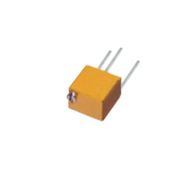
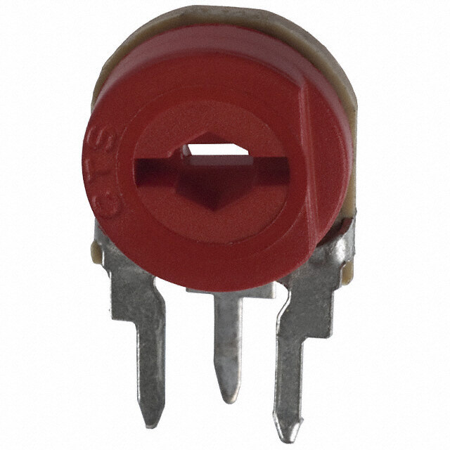
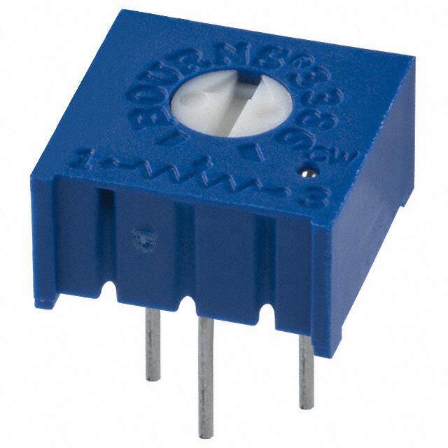
ICGOO电子元器件商城为您提供ST32ETA105由Copal Electronics Inc设计生产,在icgoo商城现货销售,并且可以通过原厂、代理商等渠道进行代购。 ST32ETA105价格参考。Copal Electronics IncST32ETA105封装/规格:微调电位计, 1 MOhms 0.125W,1/8W J 引线 表面贴装 微调电位器 金属陶瓷 1 匝 顶部调节。您可以下载ST32ETA105参考资料、Datasheet数据手册功能说明书,资料中有ST32ETA105 详细功能的应用电路图电压和使用方法及教程。
Nidec Copal Electronics的ST32ETA105属于微调电位计(Trimmer Potentiometer),常用于需要精细调节电阻值的电子电路中。该型号具有紧凑的结构和良好的稳定性,适用于对空间和精度有要求的应用场景。

ST32ETA105的主要应用场景包括:

1. 工业控制设备:用于调节传感器信号、电压基准或电流控制,确保设备运行的稳定性和精度。
2. 测量仪器:如万用表、示波器等,在校准电路中进行初始设置和定期调整,以提高测量精度。
3. 通信设备:用于调节放大器偏置电压、信号强度或频率响应,确保通信质量。
4. 消费电子产品:如音频设备、电源管理模块等,用于音量调节、亮度控制或电源输出微调。
5. 汽车电子系统:如传感器模块、车载控制单元中,用于校准和补偿环境变化带来的误差。

该微调电位计具备手动调节功能,通常在电路调试阶段使用,设定后一般不再频繁调整。其高可靠性和稳定性能适合在中等环境条件下使用,广泛应用于中低功率电子设备中。
| 参数 | 数值 |
| 产品目录 | |
| 描述 | TRIMMER 1M OHM 0.125W SMD |
| 产品分类 | |
| 品牌 | Copal Electronics Inc |
| 数据手册 | |
| 产品图片 |
|
| 产品型号 | ST32ETA105 |
| rohs | 无铅 / 符合限制有害物质指令(RoHS)规范要求 |
| 产品系列 | ST-32 |
| 产品目录绘图 |
|
| 产品目录页面 | |
| 其它名称 | ST-32ETA105 |
| 功率(W) | 0.125W,1/8W |
| 包装 | 带卷 (TR) |
| 圈数 | 单路 |
| 大小/尺寸 | 方形 - 0.134" 长 x 0.134" 宽 x 0.079" 高(3.40mm x 3.40mm x 2.00mm) |
| 安装类型 | 表面贴装 |
| 容差 | ±20% |
| 标准包装 | 500 |
| 温度系数 | ±100ppm/°C |
| 电阻(Ω) | 1M |
| 电阻材料 | 金属陶瓷 |
| 端子类型 | J 引线 |
| 调节类型 | 顶部调节 |


- 商务部:美国ITC正式对集成电路等产品启动337调查
- 曝三星4nm工艺存在良率问题 高通将骁龙8 Gen1或转产台积电
- 太阳诱电将投资9.5亿元在常州建新厂生产MLCC 预计2023年完工
- 英特尔发布欧洲新工厂建设计划 深化IDM 2.0 战略
- 台积电先进制程称霸业界 有大客户加持明年业绩稳了
- 达到5530亿美元!SIA预计今年全球半导体销售额将创下新高
- 英特尔拟将自动驾驶子公司Mobileye上市 估值或超500亿美元
- 三星加码芯片和SET,合并消费电子和移动部门,撤换高东真等 CEO
- 三星电子宣布重大人事变动 还合并消费电子和移动部门
- 海关总署:前11个月进口集成电路产品价值2.52万亿元 增长14.8%
PDF Datasheet 数据手册内容提取
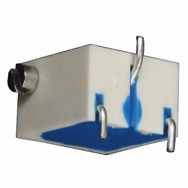
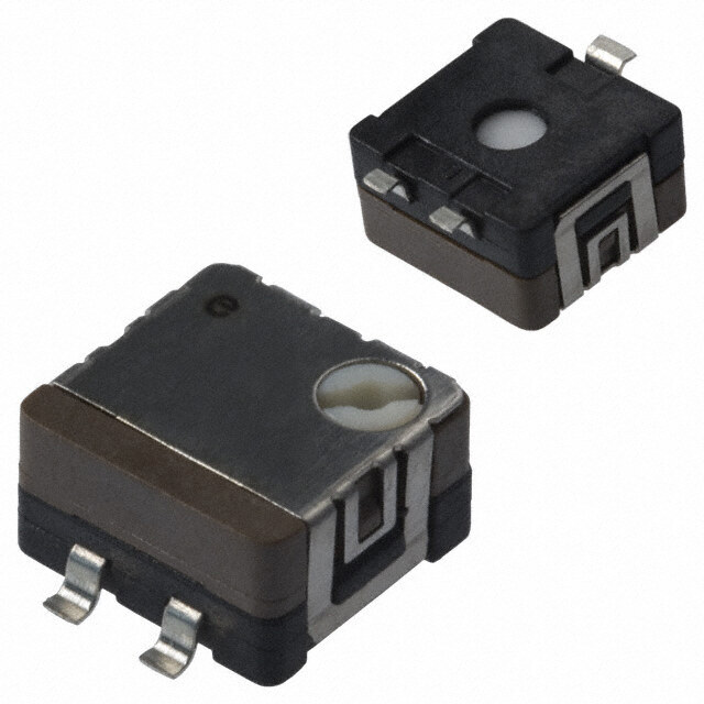
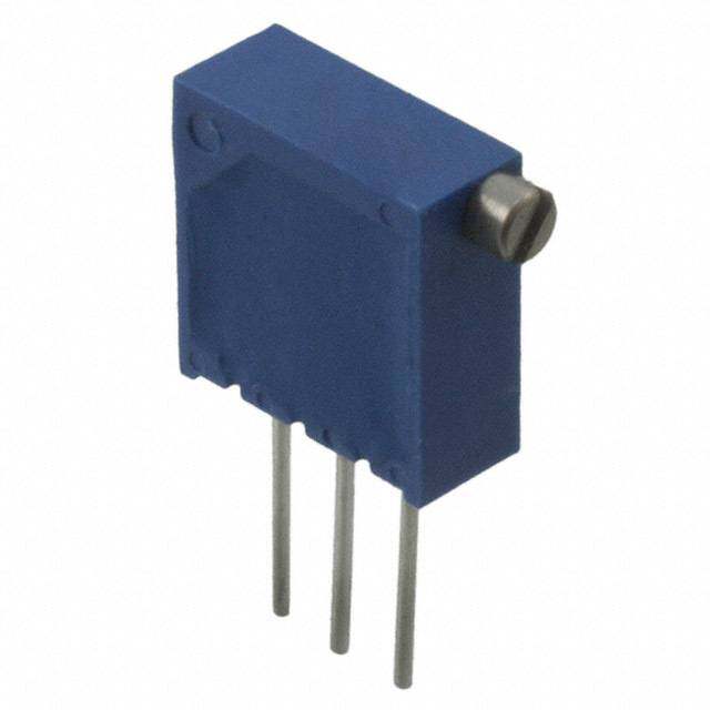
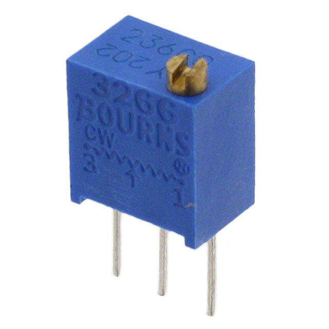
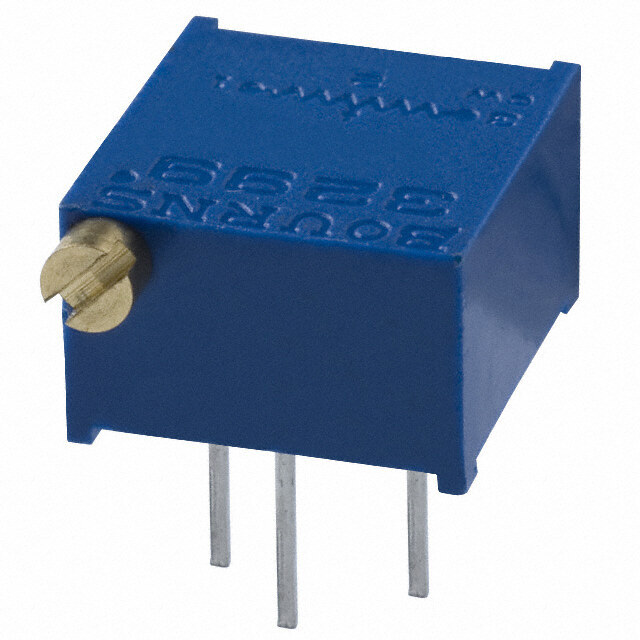
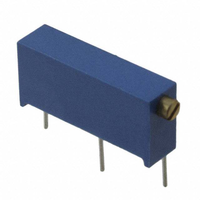
ST-32 SURFACE MOUNT CERMET TRIMMERS (SINGLE TURN) INTERNAL STRUCTURE RoHS compliant 1 7 2 6 5 3 4 8 9 Part name Material Flammability ■ FEATURES 1 Wiper Multi metal alloy (cid:2)(cid:3)RoHS compliant 2 Cover Stainless steel (SUS 304) — (cid:2)(cid:3)Rotor with a cross slot for ease of adjustment (cid:2)(cid:3)Leaded terminals provide strong as adhesive strength 3 Housing Epoxy UL94V-0 against P.C.B. bending (cid:2)(cid:3)J-hook, Gull wing and leaded terminal configurations 4 Terminal pin Copper alloy, Sn-Cu-plated (cid:2)(cid:3)Sealed (Washable: Refer to page 698.) — 5 Base element Ceramic 6 “O” ring Silicone rubber UL94HB 7 Rotor Polyphenylenesulphide UL94V-0 8 Electrode Ag-Pd cermet — 9 Resistive element RuO cermet 2 ■ PART NUMBER DESIGNATION S T - 3 2 E T A 1 0 0 Ω ( 1 2 ) Series name Resistance code Terminal pin Resistance value E:Sn-Cu (Lead-free) Form of packaging Product shape (Shape of terminal) T:Taping (Reel) A, G:J-hook Blank:Bulk in plastic bag B, H:Gull wing ※Please refer to the LIST OF PART NUMBERS when placing orders.
ST-32 SURFACE MOUNT TRIMMERS ■ LIST OF PART NUMBERS 〈Nominal resistance values〉 Form of packaging A 10 Ω A 20 Ω 50 Ω 100 Ω 200 Ω 300 Ω 500 Ω Adjustment Shape of 1 kΩ 2 kΩ 3 kΩ 5 kΩ 10 kΩ 20 kΩ 30 kΩ position terminal Taping (reel) Plastic bag 50 kΩ 100 kΩ 200 kΩ 500 kΩ 1 MΩ 2 MΩ Fig.1 Top A (J-hook) ST-32ETA ST-32EA The products indicated by A mark are manufactured upon receipt of order basis. adjustment B (Gull wing) ST-32ETB ST-32EB Side G (J-hook) ST-32ETG ST-32EG ※The part numbers on the left are all available with the respective comb i na tion of <Nominal resistance values> (Fig. 1). adjustment H (Gull wing) ST-32ETH ST-32EH ※Verify the above part numbers when placing orders. ※Taping specification is not sold separately and must be purchased in reel units. Pieces in package 500 pcs./reel 100 pcs./pack ■MECHANICAL CHARACTERISTICS Mechanical angle 250 ° (1 turn) Operating torque 5 mN·m {51 gf·cm} maximum ■ ELECTRICAL CHARACTERISTICS Stop strength 20 mN·m {204 gf·cm} minimum Nominal resistance range 10 Ω ~ 2 MΩ Rotational life 100 cycles [ΔR/R ≦ ± (2 Ω +3 %)] Resistance tolerance ± 20 % Thrust to rotor 5 N {0.51 kgf} minimum Power ratings 0.125 W (70 °C) 0 W (125 °C) Solderability 245 ± 3 °C, 2 ~ 3 s Resistance law Linear law (B) Shear (Adhesion) 5 N {0.51 kgf} 10 s Maximum input voltage DC200 V or power rating, whichever is smaller Substrate bending Width 90 mm, bend 3 mm, 5 s, 1 time Maximum wiper current 100 mA or power rating, whichever is smaller Pull-off strength 5 N {0.51 kgf} 10 s Effective electrical angle 210 ° (1 turn) { }:Reference only End resistance 1 % or 2 Ω, whichever is greater ■ ENVIRONMENTAL CHARACTERISTICS C.R.V. 1 % or 3 Ω, whichever is greater Operating temp. range −55 ~ 125 °C Test item Test conditions Specifications Temp. coefficient 10 Ω ~ 50 Ω : ± 250 10-6/°C maximum Thermal shock−65 ~ 125 °C (0.5 h), 5 cycles [ΔR/R ≦ 2 %] 100 Ω ~ 2 MΩ : ± 100 10-6/°C maximum [S.S. ≦ 1 %] −10 ~ 65 °C (80 ~ 98 %), Insulation resistance 1000 MΩ minimum (DC500 V) Humidity 10 cycles, 240 h [ΔR/R ≦ 2 %] 981 m/s2, 6 ms Dielectric strength AC500 V, 60 s Shock 6 directions for 3 times each Net weight AApppprrooxx.. 00..1015 gg ((SSTT--3322EEGA,, EEBH)) Vibration ((AAmccpelilteurdaeti)o n1).5 129 m6 mm /os2r, [Δ[S.RS/.R ≦ ≦ 1 1% %] ] 10 ~ 2000 Hz, 3 directions, 12 times each 〈Reflow profile for soldering heat evaluation〉 Load life 70 °C, 0.125 W, 1000 h [ΔR/R ≦ 3 %] [S.S. ≦ 1 %] [ΔR/R ≦ 2 %] Low temp. operation −55 °C, 2 h [S.S. ≦ 2 %] [ΔR/R ≦ 3 %] 2(5℃0) Peak : 250+ 50℃ High temp. exposure 125 °C, 250 h No l[eSa.kSs .( N≦o c 2on t%inu]ous Immersion seal 85 °C, 60 s Over 230 ℃ bubbles) 200 Pre Heating Zone e ur 180 ℃ at Flow : 260 ± 3 °C as the temperature in a er 150 150 ℃ pot of molten solder, immers ion from head of Temp 100 90 (cid:156) 30 s Soldering heat Rttiemre mefslio nmawal xt:io mP buemaac.kks itdeem opf eboraartdu,r e5 ~2 565 s ,° tCwo [ΔR/R ≦ 1 %] 30 (cid:156) 10 s (Please refer to the profile below.) 手はんだ Manual soldering:350 ± 10 °C, 3 ~ 4 s 50 Soldering Zone Heating time Reflow : two times maximum ΔR/R:Change in total resistance S.S. :Setting stability
ST-32 SURFACE MOUNT TRIMMERS ■ MAXIMUM INPUT RATINGS Nominal resistance Maximum input Maximum wiper Resistance code values (Ω) voltage (V) current (mA) A 10 11 1.00 100 A 20 21 1.58 79.1 50 51 2.50 50.0 100 12 3.53 35.4 200 22 5.00 25.0 300 32 6.12 20.4 500 52 7.91 15.8 1 k 13 11.2 11.2 2 k 23 15.8 7.91 3 k 33 19.4 6.45 5 k 53 25.0 5.00 10 k 14 35.4 3.54 20 k 24 50.0 2.50 30 k 34 61.2 2.04 50 k 54 79.1 1.58 100 k 15 112 1.12 200 k 25 158 0.79 500 k 55 200 0.40 1 M 16 200 0.20 The products indicated by A mark are manufactured upon 2 M 26 200 0.10 receipt of order basis. ■ RECOMMENDED P.C.B. PAD OUTLINE DIMENSIONS (cid:2)(cid:3)ST-32EA, EG (cid:2)(cid:3)ST-32EB, EH (Unit : mm) 1.6 1.6 5 1. 2 2. 9 0. 0 6 4. 9 1 0. 0 6 2 1 1. 1.2 0.8 1.2 1.9 3.2 For reflow soldering 1.2 0.8 1.2 3.2 Note) The zero point is the center of mounting.
ST-32 SURFACE MOUNT TRIMMERS ■ OUTLINE DIMENSIONS Unless otherwise specified, tolerance : ± 0.3 (Unit : mm) 1 3 (cid:2)(cid:3)ST-32EA CW rotation 2 Top adjustment ※Note the terminal position. Cross slot for a 0 bit driver, depth : 0.45 Production date code & Lead-free Identification mark 1 digit (Location reversed every 2 years) 2 1.5 0.5 1 0.6 3.4 1.9 3.5 2 0.05 2 – 0.7 3.4 2 t = 0.12 2.1 3 1 Resistance code 2 digits (cid:2)(cid:3)ST-32EB Top adjustment Cross slot for a 0 bit driver, depth : 0.45 Production date code & Lead-free Identification mark 2 1.5 1 digit (Location reversed every 2 years) 0.5 1 3.4 1.9 4.4 2 0.05 2 – 0.7 3.4 2 t = 0.12 2.1 3 1 Resistance code 2 digits
ST-32 SURFACE MOUNT TRIMMERS ■ OUTLINE DIMENSIONS Unless otherwise specified, tolerance : ± 0.3 (Unit : mm) 1 3 (cid:2)(cid:3)ST-32EG CW rotation 2 Side adjustment ※Note the terminal position. Cross slot for a 0 bit driver, depth : 0.45 Production date code & Lead-free Identification mark 1 digit (Location reversed every 2 years) Adjustment 3.6 1.5 3 1 3.5 2.4 0.5 0.2 2 – 0.6 1 4.7 1.9 1.7 2.6 1.1 1 t = 0.12 Resistance code 2 digits 2 (cid:2)(cid:3)ST-32EH Side adjustment Cross slot for a 0 bit driver, depth : 0.45 Production date code & Lead-free Identification mark Adjustment 1 digit (Location reversed every 2 years) 3.6 1.5 3 2.4 1 0.5 3.5 2 – 0.6 0.2 4 1. 4.7 1.9 1.7 6 2. 1.3 t = 0.12 1 Resistance code 2 digits 2
ST-32 SURFACE MOUNT TRIMMERS ■ PACKAGING SPECIFICATIONS <Taping packaging specifications> (cid:2)(cid:3)Taping version is packaged in 500 pcs. per reel. Maximum number of consecutive missing pieces = 2 Orders will be accepted for units of 500 pcs., i.e., 500, Leader length and reel dimension are shown in the 1000, 1500 pcs., etc. diagrams below. (cid:2)(cid:3)ST-32ETA, ETB versions are boxed with 4 reels (2000 pcs.). ST-32ETG, ETH versions are boxed with one reel (500 pcs.). (cid:2)(cid:3)EMBOSSED TAPE DIMENSIONS (cid:2)(cid:3)REEL DIMENSIONS (Conforms to JIS C 0806-3) (In accordance with EIAJ ET-7200A) (Unit: mm) Empty Filled Empty 13+1(ETA/ETB) 0 13.4±1(ETG/ETH) End Head 40 mm miDn.irection of feed 20 pitches m40in0L. meamde mrin. φ21±0.8 2±0.5 +1(ETA/ETB)0 0(ETG/ETH)min. φ13±0.2 φ60 5 φ 15.4±1(ETA/ETB) φ180 – 01.5(ST-32ETA/ETB) 17.4±1(ETG/ETH) φ254±2 (ST-32ETG/ETH) (cid:2)(cid:3)ST-32ETA, ETB (cid:2)(cid:3)ST-32ETG, ETH 8 ± 0.1 4 ± 0.1 2 ± 0.05 ± 0.1 0.3 (cid:156) 0.1 8 (cid:156) 0.1 (cid:3)1.5 0+0.1 2 1.75 (cid:3)1.5 02+0.1 (cid:156) 0.1 4 (cid:156)2 0.1 1.75 0.1(cid:156) 0.4 (cid:156) 0.1 I(nSsTt-a3ll2aEtiHo)n example 5 0 5.5 ± 0. 12 Installation example 5.5 0.1(cid:156) 12 (ST-32EA) 2.5 3 1 3 1 Direction of feed 5.5 max. Direction of feed <Bulk pack specifications> (cid:2)(cid:3)Unit of bulk in a plastic bag is 100 pcs. per pack. (cid:2)(cid:3)Boxing of bulk in a plastic bag is performed with 500 pcs. per box.