ICGOO在线商城 > 传感器,变送器 > 磁性传感器 - 开关(固态) > SS549AT
 Datasheet下载
- 型号: SS549AT
- 制造商: Honeywell Solid State Electronics
- 库位|库存: xxxx|xxxx
- 要求:
| 数量阶梯 | 香港交货 | 国内含税 |
| +xxxx | $xxxx | ¥xxxx |
查看当月历史价格
查看今年历史价格
SS549AT产品简介:
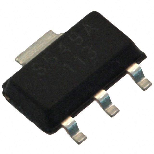
ICGOO电子元器件商城为您提供SS549AT由Honeywell Solid State Electronics设计生产,在icgoo商城现货销售,并且可以通过原厂、代理商等渠道进行代购。 SS549AT价格参考¥23.92-¥34.50。Honeywell Solid State ElectronicsSS549AT封装/规格:磁性传感器 - 开关(固态), Digital Switch Unipolar Switch Open Collector Hall Effect SOT-89B。您可以下载SS549AT参考资料、Datasheet数据手册功能说明书,资料中有SS549AT 详细功能的应用电路图电压和使用方法及教程。
霍尼韦尔(Honeywell Sensing and Productivity Solutions)的SS549AT是一款固态磁性开关传感器,属于数字式全极性霍尔效应传感器。该器件无需物理接触即可检测磁场变化,具有高可靠性、长寿命和快速响应的特点。

SS549AT广泛应用于需要非接触式位置检测和运动控制的场景。常见应用包括:工业自动化设备中的限位开关、液位检测(如油箱或水箱浮子系统)、门/盖状态监测(如家电、机柜安全开关)、电动工具和手持设备中的启动控制等。在消费电子领域,可用于笔记本电脑、智能家电的开合检测。此外,也适用于汽车系统,如座椅位置识别、变速杆位置检测等。

由于其全极性设计(可响应南北两极磁场),SS549AT安装使用灵活,简化了磁体装配过程。器件工作稳定,抗干扰能力强,适合在较宽温度范围和恶劣环境中运行,是替代传统机械开关的理想选择。
| 参数 | 数值 |
| 产品目录 | |
| 描述 | SENSOR UNIPOLAR HALL-EFFECT |
| 产品分类 | 磁性传感器 - 霍尔效应,数字开关,线性,罗盘 (IC) |
| 品牌 | Honeywell Sensing and Control |
| 数据手册 | |
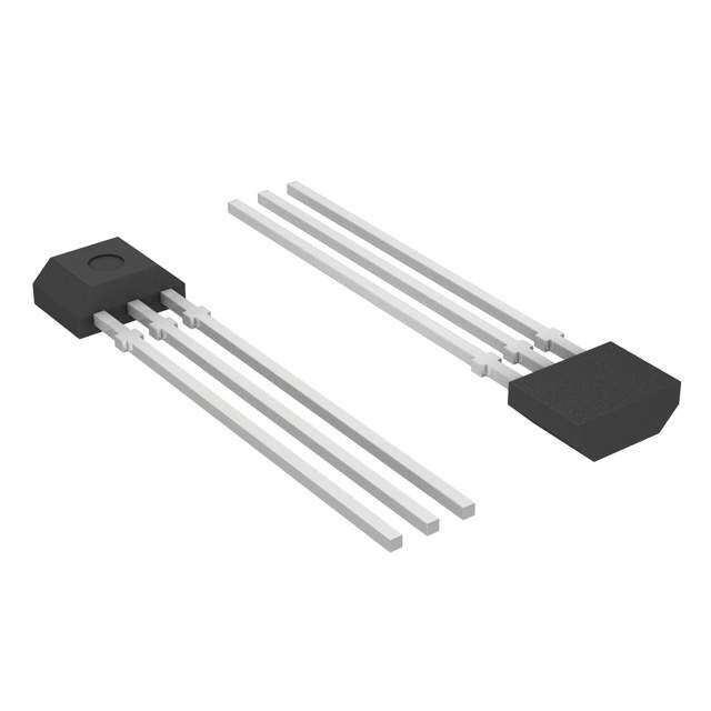
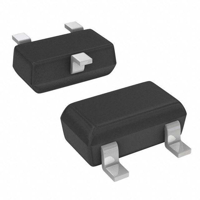
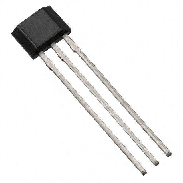
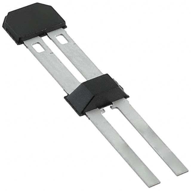
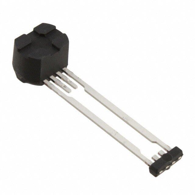
| 产品图片 |
|
| 产品型号 | SS549AT |
| rohs | 无铅 / 符合限制有害物质指令(RoHS)规范要求 |
| 产品系列 | SS500 |
| 供应商器件封装 | SOT-89B |
| 其它名称 | 480-3614-1 |
| 包装 | 剪切带 (CT) |
| 封装/外壳 | TO-243AA |
| 工作温度 | -40°C ~ 150°C |
| 感应范围 | 390G 跳闸,235G 释放 |
| 标准包装 | 1 |
| 特性 | - |
| 电压-电源 | 3.8 V ~ 30 V |
| 电流-电源 | 8.7mA |
| 电流-输出(最大值) | 20mA |
| 类型 | 单极开关 |
| 输出类型 | 数字,开路集电极 |


- 商务部:美国ITC正式对集成电路等产品启动337调查
- 曝三星4nm工艺存在良率问题 高通将骁龙8 Gen1或转产台积电
- 太阳诱电将投资9.5亿元在常州建新厂生产MLCC 预计2023年完工
- 英特尔发布欧洲新工厂建设计划 深化IDM 2.0 战略
- 台积电先进制程称霸业界 有大客户加持明年业绩稳了
- 达到5530亿美元!SIA预计今年全球半导体销售额将创下新高
- 英特尔拟将自动驾驶子公司Mobileye上市 估值或超500亿美元
- 三星加码芯片和SET,合并消费电子和移动部门,撤换高东真等 CEO
- 三星电子宣布重大人事变动 还合并消费电子和移动部门
- 海关总署:前11个月进口集成电路产品价值2.52万亿元 增长14.8%


PDF Datasheet 数据手册内容提取
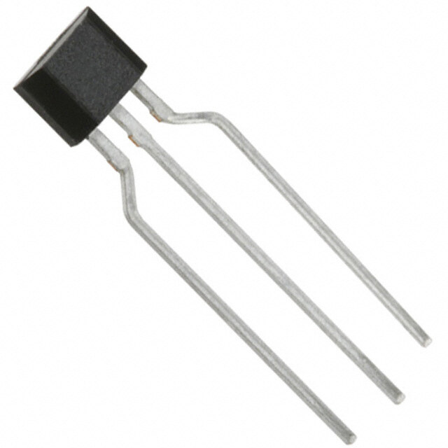
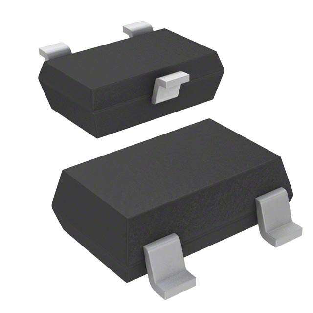
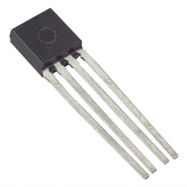
Bipolar, Latching, and Unipolar Hall-effect Digital 32320997 Position Sensor ICs: SS400 Series, SS500 Series Issue B Datasheet FEATURES • Quad Hall IC design minimizes mechanical stress effects • Temperature-compensated magnetics help provide stable operation over a wide temperature range of -40°C to 150°C [-40°F to 302°F] • Broad, inclusive supply voltage capability from 3.8 Vdc to 30 Vdc for application flexibility • Digital, open collector sinking output for easy interfacing with a variety of common electronic circuits • High sensitivity versions available for potential applications requiring high accuracy or wide gaps • Bipolar, latching or unipolar magnetics DESCRIPTION POTENTIAL APPLICATIONS The SS400 Series and SS500 Series are small and versatile • Industrial: Speed and RPM (revolutions per minute) sensing, digital Hall-effect devices that are operated by the magnetic tachometer, counter pickup, flow-rate sensing, brushless dc field from a permanent magnet or an electromagnet, and (direct current) motor commutation, motor and fan control, are designed to respond to alternating North and South robotics control poles, or to a South pole only. They are available in bipolar, • Transportation: Speed and RPM (revolutions per minute) latching or unipolar magnetics. On-board regulation provides sensing, tachometer, counter pickup, motor and fan control, stable operation over a 3.8 Vdc to 30 Vdc supply voltage electric window lift, convertible roof position range. These sensors are capable of continuous 20 mA • Medical: Motor assemblies, medication dispensing control sinking output and may be cycled as high as 50 mA max. The 3.8 V capability allows for use in many potential low PORTFOLIO voltage applications. The digital, open collector sinking-type Other bipolar, latching and unipolar Hall- output is easily interfaced with a wide variety of electronic effect digital sensor ICs include: circuits. To provide reliable products and consistent quality, • SS360NT, SS360ST, SS360ST-10K, SS460S, SS460S-T2 the SS400 Series products are tested at both 25°C [75°F] • VF360NT, VF360ST, VF460S and 125°C [257°F]. All catalog listings are qualified for • SS361RT, SS461R operation up to 150°C [302°F]. For design flexibility, these • SS361CT, SS461C product are available in the following package styles: • SS340RT, SS440R Series • SS400 Series: Flat TO-92-style: • SS360PT, SS460P, SS460P-T2 - SS4XX: Straight standard leads, bulk pack • SS311PT, SS411P - SS4XX-L: Straight long leads, bulk pack - SS4XX-T2: Formed leads, ammopack tape-in-box - SS4XX-T3: Straight standard leads, ammopack tape-in-box - SS4XX-S: Surface mount, bulk pack - SS4XX-SP: Surface mount, pocket tape and reel • SS500 Series: SOT-89B, pocket tape and reel Sensing and Productivity Solutions
Bipolar, Latching, or Unipolar Hall-effect Digital Sensor ICs: SS400 Series, SS500 Series Table 1. Performance Specifications (Applies to both SS400 series and 500 Series, unless otherwise noted.) Characteristic Condition Min. Typ. Max. Unit Supply voltage (V)1 — 3.8 — 30 Vdc s Rated sinking current (I ) — — 20 — mA sink Current consumption: on: SS400 Series V = 30 Vdc, I = 20 mA, -40°C < T < 150°C, B > operate max. — — 10.0 s sink SS500 Series V = 30 Vdc, -40°C < T < 150°C, B > operate max. — — 10.0 mA s off: SS400 Series V = 30 Vdc, I = 20 mA, -40°C < T < 150°C, B > operate max. — — 9.0 s sink SS500 Series V = 30 Vdc, I = 20 mA, -40°C < T < 150°C, B > release min. — — 10.0 s sink V : sat SS400 Series V = 3.8 Vdc, I = 20 mA, B > operate max. — — 0.4 V s sink SS500 Series V = 3.8 Vdc, B > operate max. — — 0.4 s Output leakage current: SS400 Series V = 24 V, Vout = 30 V, B < release min. — — 0.4 uA s SS500 Series — — — 10.0 Output switching time: rise V = 12 V, R = 1.6 kOhm, C = 20 pF, T = 25°C [77°F] — — 1.5 us s L L fall V = 12 V, R = 1.6 kOhm, C = 20 pF, T = 25°C [77°F] — — 1.5 s L L Operating temperature — -40 [-40] — 150 [302] °C [°F] Storage temperature — -50 [-58] — 150 [302] °C [°F] Soldering temp. and time: SS400 Series wave soldering process: 250°C to 260°C [482°F to 500°F] for 3 s max. SS500 Series infrared reflow process: peak temperature 245°C [473°F] for 10 s max. 1For supply voltages above 24 Vdc, a capacitor may be needed between the output and supply pins to ensure proper operation. NOTICE NOTICE CAUTION ELECTROSTATIC These Hall-effect sensor ICs may have an The magnetic field strength (Gauss) required SENSITIVE DEVICES initial output in either the ON or OFF state if to cause the switch to change state (operate DO NOT OPEN OR HANDLE powered up with an applied magnetic field in the and release) will be as specified in the STATIC EFRXCEEEP WTO ART KAS TATION differential zone (applied magnetic field >Brp ESD SENSITIVITY: magnetic characteristics. To test the switch and <Bop). Honeywell recommends allowing CLASS 3 against the specified limits, the switch must 10 us after supply voltage has reached 5 V for the output voltage to stabilize. be placed in a uniform magnetic field. Figure 1. Circuit Diagram V (+) s Trigger Hall-effect Circuit Output (O) Sensor IC and Amplifier Ground (-) 2 Sensing and Productivity Solutions
Bipolar, Latching, or Unipolar Hall-effect Digital Sensor ICs: SS400 Series, SS500 Series Table 2. Absolute Maximum Specifications Characteristic Min. Typ. Max. Unit Supply voltage (V -1 — 30 V s) Applied output voltage (V : out) SS400 Series -0.5 — 30 V SS500 Series (off) — — 30 Output current (I : sink) V = -1 Vdc to 24 Vdc — — 50 s V = 24 Vdcto 25 Vdc — — 37 s V = 25 Vdc to 26 Vdc — — 33 s mA V = 26 Vdc to 27 Vdc — — 28 s V = 27 Vdc to 28 Vdc — — 24 s V = 28 Vdc to 29 Vdc — — 19 s V = 29 Vdc to 30 Vdc — — 15 s Magnetic flux — — no limit Gauss NOTICE Absolute maximum ratings are the extreme limits the device will momentarily withstand without damage to the device. Electrical and mechanical characteristics are not guaranteed if the rated voltage and/ or currents are exceeded, nor will the device necessarily operate at absolute maximum ratings. Figure 2. Magnetic Activation SS500 Series SS400 Series N S S N N S S N Label side Label side South pole toward IC: North pole toward IC: South pole toward IC: North pole toward IC: Output = Low Output = High Output = Low Output = High Figure 3. Circuit Diagrams +DC +5 Vdc +10 Vdc 150 mA 5 Vdc 5 Vdc R 5 Vdc 5 Vdc 47 Ohm R Load R 1.2 kOhm + 10 kOhm + R1 + 550 Ohm 2N2222 Sensor TTL or Sensor R Sensor NPN IC DTL Gate IC 100 Ohm IC Transistor LED 50 mA - - AC +13 Vdc +15 Vdc HI 5 Vdc +15 Vdc HI 13 Vdc 47 OhmR 2PNN3P638 10 Vdc 47 kOhRm1 PNP 4.7 kOhmR PNP Sen+sor 550 OhRm1 Tr1a0n0s imstAor Sen+sor 750 OhmR R Transistor Load Sens+or 1.8 kOhRm1 R Transistor Load IC SCR TRIAC Relay IC IC coil R R - LOW LOW Sensing and Productivity Solutions 3
Bipolar, Latching, or Unipolar Hall-effect Digital Sensor ICs: SS400 Series, SS500 Series Table 3. Magnetic Specifications Magnetic Characteristic (Gauss) e ur Bipolar Unipolar Latching t a Operating er T T T T T T T p Characteristic A A A A A A A m 1 1 3 3 1 1 3 3 9 9 1 1 6 6 1 1 1 1 4 4 4 4 4 4 6 6 6 6 Te 4 5 4 5 4 5 4 5 4 5 4 5 4 5 S S S S S S S S S S S S S S S S S S S S S S S S S S S S operate: minimum NS NS 50 110 285 5 — 100 maximum 70 140 135 215 435 110 100 200 -40°C release: [-40°F] minimum -70 -140 20 80 210 -110 -100 -200 maximum NS NS 120 190 360 -5 -5 -100 differential (min.) 15 20 15 25 30 50 50 200 operate: minimum NS NS 53 110 305 5 100 maximum 65 140 117 190 400 90 185 0°C release: [0°F] minimum -65 -140 20 80 230 -90 -185 maximum NS NS 99 165 325 -5 -100 differential (min.) 15 20 15 25 30 50 200 operate: minimum NS NS 55 110 310 10 100 maximum 60 140 115 180 390 85 180 25°C release: [77°F] minimum -60 -140 20 75 235 -85 -180 maximum NS NS 95 155 315 -10 -100 differential (min.) 15 20 20 25 30 50 200 operate: minimum NS NS 45 90 290 — 10 95 maximum 60 140 120 180 400 400 85 180 85°C release: [185°F] minimum -60 -140 15 70 215 315 -85 -180 maximum NS NS 105 165 325 — -10 -95 differential (min.) 12 20 15 15 30 30 50 190 operate: minimum NS NS 40 80 270 290 5 80 maximum 65 140 123 190 410 400 100 180 125°C release: [257°F] minimum -65 -140 15 60 200 215 -100 -180 maximum NS NS 115 180 340 325 -5 -80 differential (min.) 12 20 8 10 30 30 50 160 operate: minimum NS NS 35 65 260 5 70 maximum 70 140 125 200 420 110 185 150°C release: [302°F] minimum -70 -140 10 55 185 -110 -185 maximum NS NS 120 195 345 -5 -70 differential (min.) 10 20 5 5 30 50 140 4 Sensing and Productivity Solutions
Bipolar, Latching, or Unipolar Hall-effect Digital Sensor ICs: SS400 Series, SS500 Series Figure 4. Operate and Release Point Performance Graphics SS411/SS511AT SS413/SS513AT 250 250 200 200 uss) 150 uss) 150 Operate max. sity (Ga 105000 OOppeerraattee mnoamx.. sity (Ga 105000 Operate nom. n Release nom. n nte -50 Release min. nte -50 Release nom. d I-100 d I -100 el-150 el -150 Release min. Fi Fi -200 -200 -250 -250 -40 0 25 85 125 150 -40 0 25 85 125 150 Temperature (°C) Temperature (°C) SS441/SS541AT SS443/SS443AT s)140 220 aus120 ROepleeraastee mmaaxx.. 200 ORepleeraastee mmaaxx.. Field Intensity (G108642000000 ROepleeraastee mmiinn.. ntensity (Gauss)11111864208000000 -40 0 T2e5mperature (°8C5) 125 150 eld I 60 ORepleeraastee mmiinn.. Fi 40 20 0 -40 0 25 85 125 150 Temperature (°C) SS449/SS549AT SS461/SS561AT 250 420 Operate max. 200 ss) 150 u ss)380 Ga 100 Operate max. au y ( 50 y (G340 Release max. nsit 0 ROepleeraastee mmainx.. eld Intensit320600 Operate min. Field Inte---112-50500000 Release min. Fi -250 -40 0 25 85 125 150 220 Temperature (°C) 180 Release min. -40 0 25 85 125 150 Temperature (°C) SS466/SS566AT 250 200 ss) 150 Operate max. u a 100 G Operate min. y ( 50 t si 0 n te -50 n Release max. d I-100 el-150 Fi Release min. -200 -250 -40 0 25 85 125 150 Temperature (°C) Sensing and Productivity Solutions 5
Bipolar, Latching, or Unipolar Hall-effect Digital Sensor ICs: SS400 Series, SS500 Series Figure 5. SS400 Series Flat TO-92-Style Mounting and Dimensional Drawings (For reference only: mm/[in].) SS4XX: Straight Standard Leads, Bulk Pack SS4XX-L: Straight Long Leads, Bulk Pack 4,06 4,06 [0.160] [0.160] 1,57 1,57 [0.062] [0.062] 2,50 0,76 2,50 0,76 [0.098] [0.030] [0.098] [0.030] 3,00 3,00 [0.118] [0.118] 3 X[0 0.0,5262 M]ax. 15,5 - 14,4 3 X[0 0.0,5262 M]ax. [0.61 - 0.57] 18,7 [0.74] + - 0 + - 0 3X 0,38 3X 0,38 [0.015] 2X 1,27 [0.015] [0.05] 3X 0,38 3X 0,38 [0.015] [0.015] SS4XX-T2: Formed Leads, Ammopack Tape-in-Box 4,06 [0.160] 1,57 [0.062] 2,50 [0.098] 0,76 [0.030] 3,00 [0.118] 2X 3,35 [0.13] 15,5 - 14,4 [0.61 - 0.57] + - 0 3X 0,38 0,56 Max. 3X 0,38 [0.015] [0.022] [0.015] 2X 2,54 [0.10] 1,00 Max. 1,00 Max. [ 0 [. 0013.,00930]9 M]ax. Sensor 1 [ 01.,00309 M]ax. [0.039]Adhesive tape Sensor 24 Sensor 1 0,50 Max. [0.020] 11,00 Fold [0.433] 20,00 [0.787] 6,00 [0.236] 9,001 [0.354] 18,00 [7,09] Fold [ 0 0[ 01.,05.,0425522 M6 M]]aaxx.. [60,.23551][20,.57]0 ø[04.1,0507] 6 Sensing and Productivity Solutions
Bipolar, Latching, or Unipolar Hall-effect Digital Sensor ICs: SS400 Series, SS500 Series Figure 5. SS400 Series Flat TO-92-Style Mounting and Dimensional Drawings (For reference only: mm/[in].) SS4XX-T3: Straight Standard Leads, Ammopack Tape-in-Box 4,06 [0.160] 1,57 [0.062] 2,50 0,76 [0.098] [0.030] 3,00 [0.118] 3X 0,56 Max. [0.022] 15,5 - 14,4 [0.61 - 0.57] + - 0 3X 0,38 3X 0,38 [0.015] 2X 1,27 [0.015] [0.05] 1,00 Max. 1,00 Max. [0.039] [0.039] 1,00 Max. Sensor 1 [ 01.,00309 M]ax. Adhesive tape Sensor 24 SSeennssoorr 11 [0.039] 0,50 Max. [0.020] 11,00 Fold [0.433] 20,00 [0.787] 6,00 [0.236] 9,001 [0.354] 18,00 [7,09] Fold [ 00 [ .,0105.,25042 52M]6 Ma]xa.x. [60,.2355]1[20,.57]0 ø[04.1,0507] Sensing and Productivity Solutions 7
Bipolar, Latching, or Unipolar Hall-effect Digital Sensor ICs: SS400 Series, SS500 Series Figure 5. SS400 Series Flat TO-92-Style Mounting and Dimensional Drawings (continued) SS4XX-S: Surface Mount, Bulk Pack 4,06 [0.160] PCB Land Pattern 1,57 [0.062] 2,50 0,76 [0.098] [0.030] 1,524 [0.060] 3,00 [0.118] 2,032 [0.080] 1,52 [0.060] 0,813 3,18 [0.032] [0.125] + - 0 3X 0,38 3X 0,56 Max. 3X 0,38 [0.015] [0.022] [0.015] SS4XX-SP: Surface Mount, Pocket Tape and Reel 8,00 [0.315] ø1,5 4,00 [0.059] [0.157] 0,41 Max. 2,00 A 4,06 [0.006] [0.079] [0.160] 1,75 1,57 [0.069] [0.062] 2,50 0,76 [0.098] [0.030] 5,50 [0.217] 3,00 [0.118] 6,60 1,52 [0.260] 12,00 [0.060] [0.472] 3,18 [0.125] + - 0 3X 0,38 3X 0,56 Max. 3X 0,38 [0.015] [0.022] [0.015] 4,41 A 1,70 0,10 [0.174] [0.067] [0.004] Section A-A Top cover tape 12,2 [0.480] Measured at hub 18,39 Max. [0.724] PCB Land Pattern ø33,02 Measured at hub [1.300] 1,524 [0.060] 2,032 [0.080] 0,813 [0.032] ø50,0 [1.970] 1,5 Min. [0.059] Drive spokes ø[01.531,02] ø [71.7081] Arbor hole 8 Sensing and Productivity Solutions
Bipolar, Latching, or Unipolar Hall-effect Digital Sensor ICs: SS400 Series, SS500 Series Figure 6. SS500 Series Mounting and Dimensional Drawings (For reference only: mm/[in].) SOT-89B Sensor IC, Pocket Tape and Reel 0,965 Nominal IC [0.038] 1,70 center 0,16 Nominal IC [0.067] [0.006] center 2,49 2,39 4,16 [0.098] [0.094] [0.164] + - 0 0,05 [0.002] 2X 1,50 3X 0,41 1,37 [0.059] [0.016] [0.054] 4,39 [0.173] 7,98 [0.314] 4,50 [0.177] 3,99 1,75 [0.157] [0.069] 2,31 Max. 2,01 [0.091] 0,41 Max. A [0.0 7 9 ] ø1,50 Min. [0.016] [0.059] 5,51 0,10 [0.217] 11,99 [0.004] [0.472] 5,84 Max. Top cover tape [0.230] 4,78 [0.188] 1,91 4,60 [0.075] [0.181] A 8,00 Section A-A [0.315] 12,19 [0.480] Measured at hub 3X 1,50 Min. [0.059] 18,39 Max. ø13,00 [0.724] [0.512] ø33,02 [1.300] ø50.0 Min. [1.970] ø178 [7.01] Sensing and Productivity Solutions 9
Bipolar, Latching, or Unipolar Hall-effect Digital Sensor ICs: SS400 Series, SS500 Series Table 4. Order Guide for the SS400 Series (Flat TO-92-Style) Catalog Listing Description SS4XX SS4XX-L SS4XX: Straight standard leads, bulk pack, 1000 units/bag SS411A Bipolar SS413A Bipolar SS441A Unipolar SS443A Unipolar SS449A Unipolar SS461A Latching SS466A Latching SS4XX-L: Straight long leads, bulk pack, 1000 units/bag SS411A-L Bipolar SS413A-L Bipolar SS441A-L Unipolar SS443A-L Unipolar SS4XX-T2 SS4XX-T3 SS449A-L Unipolar SS461A-L Latching SS4XX-T2: Formed leads, ammopack tape-in-box, 5000 units/box SS413A-T2 Bipolar SS441A-T2 Unipolar SS443A-T2 Unipolar SS449A-T2 Unipolar SS461A-T2 Latching SS4XX-T3: Straight standard leads, ammopack tape-in-box, 5000 units/box SS411A-T3 Bipolar SS413A-T3 Bipolar SS441A-T3 Unipolar SS443A-T3 Unipolar SS449A-T3 Unipolar SS461A-T3 Latching SS4XX-S: Surface mount, pocket tape and reel, bulk pack, 1000 units/bag SS411A-S Bipolar SS413A-S Bipolar SS441A-S Unipolar SS443A-S Unipolar SS4XX-S SS4XX-SP SS449A-S Unipolar SS461A-S Latching SS4XX-SP: Surface mount, pocket tape and reel, 1000 units/reel SS411A-SP Bipolar SS413A-SP Bipolar SS441A-SP Unipolar SS443A-SP Unipolar SS449A-SP Unipolar SS461A-SP Latching Table 5. Order Guide for the SS500 Series (SOT-89B, Pocket Tape and Reel, 1000 Units/Reel) Catalog Listing Description SS511AT Bipolar SS513AT Bipolar SS541AT Unipolar SS543AT Unipolar SS549AT Unipolar SS561AT Latching SS566AT Latching 10 Sensing and Productivity Solutions
ADDITIONAL INFORMATION WARNING The following associated literature is available on the PERSONAL INJURY Honeywell web site at sensing.honeywell.com: DO NOT USE these products as safety or emergency stop • Product Line Guide devices or in any other application where failure of the • Product Range Guide product could result in personal injury. • Selection Guides Failure to comply with these instructions could result in • Application-specific Information death or serious injury. WARNING MISUSE OF DOCUMENTATION • The information presented in this datasheet is for reference only. Do not use this document as a product installation guide. • Complete installation, operation, and maintenance information is provided in the instructions supplied with each product. Failure to comply with these instructions could result in death or serious injury. Warranty/Remedy Honeywell warrants goods of its manufacture as being free of defective materials and faulty workmanship during the applicable warranty period. Honeywell’s standard product warranty applies unless agreed to otherwise by Honeywell in writing; please refer to your order acknowledgment or consult your local sales office for specific warranty details. If warranted goods are returned to Honeywell during the period of coverage, Honeywell will repair or replace, at its option, without charge those items that Honeywell, in its sole discretion, finds defective. The foregoing is buyer’s sole remedy and is in lieu of all other warranties, expressed or implied, including those of merchantability and fitness for a particular purpose. In no event shall Honeywell be liable for consequential, special, or indirect damages. While Honeywell may provide application assistance personally, For more information through our literature and the Honeywell web site, it is buyer’s Honeywell Sensing and Internet of Things services its customers through a sole responsibility to determine the suitability of the product in worldwide network of sales offices and the application.Specifications may change without notice. The distributors. For application assistance, information we supply is believed to be accurate and reliable as current specifications, pricing or the of this writing. However, Honeywell assumes no responsibility nearest Authorized Distributor, visit for its use. sensing.honeywell.com or call: Asia Pacific +65 6355-2828 Europe +44 (0) 1698 481481 USA/Canada +1-800-537-6945 Honeywell Sensing and Productivity Solutions 9680 Old Bailes Road Fort Mill, SC 29707 32320997-B-EN | B | 11/17 honeywell.com © 2017 Honeywell International Inc. All rights reserved.