ICGOO在线商城 > Labels, Signs, Barriers, Identification > Accessories > SPS-AUX-AS100-1
 Datasheet下载
- 型号: SPS-AUX-AS100-1
- 制造商: Honeywell Solid State Electronics
- 库位|库存: xxxx|xxxx
- 要求:
| 数量阶梯 | 香港交货 | 国内含税 |
| +xxxx | $xxxx | ¥xxxx |
查看当月历史价格
查看今年历史价格
SPS-AUX-AS100-1产品简介:
ICGOO电子元器件商城为您提供SPS-AUX-AS100-1由Honeywell Solid State Electronics设计生产,在icgoo商城现货销售,并且可以通过原厂、代理商等渠道进行代购。 SPS-AUX-AS100-1价格参考。Honeywell Solid State ElectronicsSPS-AUX-AS100-1封装/规格:Accessories, 。您可以下载SPS-AUX-AS100-1参考资料、Datasheet数据手册功能说明书,资料中有SPS-AUX-AS100-1 详细功能的应用电路图电压和使用方法及教程。
Honeywell Sensing and Productivity Solutions 旗下的型号为 SPS-AUX-AS100-1 的配件,属于工业自动化和传感解决方案中的辅助设备,主要应用于提升工业生产系统的集成性与操作效率。该产品通常作为 Honeywell 某些传感或生产力设备的配套附件,用于增强系统功能、简化安装流程或优化数据连接。

SPS-AUX-AS100-1 常见的应用场景包括:在制造生产线中,作为传感器系统或条码识别设备的辅助连接模块,用于信号扩展或电源管理;在物流与仓储系统中,配合自动识别(AutoID)设备使用,提升数据采集稳定性;也可用于工业控制柜内,实现设备间的快速对接与布线管理,提高维护效率。

该配件适用于需要高可靠性、模块化设计和快速部署的工业环境,广泛应用于汽车制造、电子装配、食品饮料、制药及配送中心等行业。其设计符合工业级标准,具备良好的抗干扰能力和环境适应性,可在较宽温度范围和复杂电磁环境中稳定运行。

总之,SPS-AUX-AS100-1 是一款面向工业自动化的功能性辅助组件,通过增强主设备的连接性与可维护性,助力企业提升整体运营效率与系统稳定性。
| 参数 | 数值 |
| 产品目录 | |
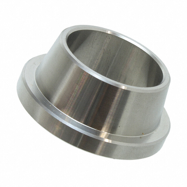
| 描述 | TOOL 1 PIECE 1" SMART ROTARY传感器硬件与配件 Assembly Tool, 1pc 25.4mm aluminum |
| 产品分类 | |
| 品牌 | Honeywell |
| 产品手册 | |
| 产品图片 |
|
| rohs | 符合RoHS无铅 / 符合限制有害物质指令(RoHS)规范要求 |
| 产品系列 | Honeywell SPS-AUX-AS100-1SPS |
| mouser_ship_limit | 该产品可能需要其他文件才能进口到中国。 |
| 数据手册 | http://sensing.honeywell.com/index.php?ci_id=143525http://sensing.honeywell.com/index.php?ci_id=143526 |
| 产品型号 | SPS-AUX-AS100-1 |
| 产品 | Assembly Tool |
| 产品培训模块 | http://www.digikey.cn/PTM/IndividualPTM.page?site=cn&lang=zhs&ptm=26094 |
| 产品种类 | 传感器硬件与配件 |
| 其它名称 | 480-5555 |
| 商标 | Honeywell |
| 标准包装 | 1 |
| 用于 | SMART Position Sensor |
| 系列 | SPS |
| 配件类型 | 装配工具 |
| 配套使用产品/相关产品 | SPS-R360D-NBMS0101 |
| 配用 | /product-detail/zh/SPS-R360D-NBMS0101/480-5553-ND/3475912 |


型号:JX-4
品牌:Honeywell Sensing and Productivity Solutions
产品名称:Labels, Signs, Barriers, Identification
获取报价


型号:LSZ53P
品牌:Honeywell Sensing and Productivity Solutions
产品名称:Labels, Signs, Barriers, Identification
获取报价


PDF Datasheet 数据手册内容提取
SMART Postion Sensors, Rotary Configuration Superior Measurement. Accurate. Reliable. Thinking. Datasheet
SMART Position Sensors Honeywell’s SMART Position Sensors are some of the most durable, adaptable, and lightweight absolute position sensors available in the industry, enabling enhanced accuracy in motion control and improving operational efficiency and safety. The two-piece, fully non-contacting design facilitates ease of integration in the application, promoting performance even in the harshest environments. Why is the SMART Position Sensor smart? Honeywell has utilized MR (Magnetoresistive) technology to provide enhanced accuracy and repeatable position sensing. The application of SMART sensing solutions provides critical system feedback, allowing for “smarter”, more efficient function. This can translate to improved productivity, a safer work environment, and minimized cost of operations. The rotary configuration joins Honeywell’s SMART Position Sensor family of proven linear and arc configurations. The SMART Position Sensor, Rotary Configuration, is a non-contacting sensing solution for absolute position sensing with enhanced accuracy. It senses the position of a magnet relative to the sensor in a range of 0° to 360°. Honeywell uses a patented combination of an ASIC (Application Specific Integrated Circuit) and an array of MR sensors to reliably determine the position of a magnet collar attached to a rotating object. The SMART Position Sensor, Rotary Configuration, fits on a 25,4 mm [1 in] shaft. A mounting tool fixture (purchased separately) provides repeatable installation. Features and Benefits Potential Applications « Non-contact design: Minimizes mechanical failure TRANSPoRTATIoN mechanisms, can reduce wear, which promotes reliability • Steering angle and durability, and minimizes downtime • Articulation angle « Combined patented MR sensor and ASIC technology • Boom arm detection provides absolute position sensing: - Helps OEMs minimize warranty costs because they don’t INduSTRIAl have to replace worn or broken component parts • Solar panels - Helps end-users minimize downtime due to fewer • Wind turbines calibration requirements « No internal moving parts: Automotive-grade potting makes the sensor more resistant to vibration, shock, and extreme temperatures, improving reliability « Repeatable output: Occurs within a 3,0 mm ±2,0 mm [0.118 in ±0.079 in] air gap between the sensor and magnet collar, expanding application opportunities • Enhanced accuracy: Measures values down to 0.01º; better sensor accuracy can provide better system accuracy in the application « IP67 and IP69K sealing: Allows for use in harsh environments such as dust, immersion up to 1 m [39.37 in] of water for 30 minutes, and high pressure water sprays « Enhanced shock and vibration resistance: Allows for use in a wide variety of tough applications • Minimal signal error: Exists up to 2,50 mm [0.10 in] of radial error, simplifying design-in • RoHS-compliant: Materials meet Directive 2002/95/EC « Indicates competitive differentiator NON-CONtaCt • MR aNd aSIC teChNOlOgy • Repeatable Output 2 sensing.honeywell.com
Rotary Configuration Table 1. Specifications1 Characteristic Component Parameter Note Sensing range 360º — Resolution 0.01º — Supply voltage 12 Vdc to 30x Vdc — Output 4 mA to 20 mA — Supply current 90 mA max. — Linearity: 25 °C [77 °F] -0.03 %FS min., 0.030 %FS max. 2, 4, 7 TC: >85 °C [158 °F] 0.0011 %FS/°C Offset: sensor 25 °C [77 °F] only -0.044 %FS min., -0.011 %FS typ., 0.022 %FS max. 3, 4, 5, 7 TC: >85 °C [158 °F] 0.0033 %FS/°C Accuracy -0.069 %FS min., 0.069 %FS max 4 Sensitivity: -4444.43 μA/° min., 44.43 μA/° typ., 44.48 μA/° max. 25 °C [77 °F] 6, 7 80 ppm/°C TC: >85 °C [158 °F] Reverse polarity -12 Vdc to -30 Vdc — Initial startup time 130 ms typ — Termination M12 connector, male 5 pin — Operating temperature --40 °C to 85 °C [-40 °F to 185 °F] — Storage temperature -40 °C to 150 °C [-40 °F to 302 °F] — Air gap 3,0 mm ±2,0 mm [0.118 in ±0.079 in] typ. — Sealing IP67, IP69K — Shock sensor and 50 G half sine wave with 11 ms duration — magnet Vibration 20 G from 10 Hz to 2000 Hz — collar Housing material ALaluminum with powder coating — Approvals CE — Mounting: screws M5 or UNC 10-24 — recommended torque 5 N m to 7 N m [44.25 in lb to 61.95 in lb] Material magnet neodymium (sintered NdFeB) — Strength only 3700 Gauss — 1Specifications are based on a non-ferrous shaft. 2Linearity: Deviations from a best fit straight line through the output, expressed as a percentage of the full scale signal range (% of 16 mA). 3Accuracy: Deviations from the ideal output line expressed as a percentage of the full scale signal range (% of 16 mA). 4%FS: Error expressed as a percentage of the output span of the sensor (% of 16 mA). 5Offset: Deviation from the ideal output at the minimum input condition, expressed as a percentage of the full scale signal range (% of 16 mA). 6Sensitivity: The slope of the output signal vs magnet travel, expressed as μA of output per degree of travel. 7TC: Temperature coefficient of a given parameter, as a percentage of the full scale signal range (% of 16 mA) per degree of temperature rise from 25 °C [77 °F]. sensing.honeywell.com 3
SMART Position Sensors Table 2. % linearity Radial Error (mm) 0 0.05 0.1 0.25 0.5 0.75 1 1.5 2 2.5 -2 0.005 0.001 0.007 0.027 0.066 0.113 0.166 0.294 0.450 0.635 -1 0.002 0.003 0.008 0.025 0.060 0.101 0.150 0.269 0.417 0.593 Air Gap 0 0.000 0.004 0.008 0.023 0.053 0.090 0.135 0.245 0.383 0.550 Error 1 0.002 0.005 0.009 0.021 0.047 0.079 0.119 0.220 0.350 0.508 (mm) 2 0.005 0.007 0.009 0.019 0.040 0.068 0.104 0.196 0.317 0.466 3 0.007 0.008 0.010 0.017 0.033 0.057 0.088 0.172 0.284 0.424 Table 3. % Accuracy Radial Error (mm) 0 0.05 0.1 0.25 0.5 0.75 1 1.5 2 2.5 -2 0 0.006 0.012 0.033 0.076 0.129 0.191 0.263 0.538 0.770 -1 0 0.005 0.011 0.029 0.069 0.118 0.176 0.245 0.509 0.733 Air Gap 0 0 0.004 0.009 0.026 0.061 0.106 0.162 0.226 0.479 0.697 Error 1 0 0.004 0.008 0.022 0.054 0.095 0.147 0.208 0.450 0.660 (mm) 2 0 0.003 0.006 0.018 0.047 0.084 0.132 0.190 0.420 0.623 3 0 0.002 0.005 0.015 0.039 0.073 0.117 0.171 0.391 0.586 NoTICE FERRouS MATERIAl Stationary ferrous material often creates an initial offset upon installation. If the stationary ferrous material never moves in relation to the sensor after the installation, and the environment remains ferrous-free, performance should be repeatable. Ensure the sensor is tested in the application. Figure 1. Sensor dimensional drawings (For reference only: mm [in].) Pinout 1 = Supply voltage (+) 2 = Test pin, connect to ground (-) MOUNTING 22,00 SURFACE 3 = Ground (-) [0.87] 4 = Output (0) 5 = Test pin, connect to ground (-) 45,10 4 3 [1.78] 30,00 DIA. [1.18] 5 M12 CONNECTOR, 80,00 DIA. MALE, 5 PINS [3.15] 1 2 3X 92,50 DIA. [3.64] 14,00 [0.55] 3X 12,5 DIA. [0.49] 3X 5,80 DIA. [3.15] 20,5 [0.81] CABLE DIRECTION FOR RIGHT ANGLE 3X 120 DEG. CONNECTOR REF: 0 DEG. 4 sensing.honeywell.com
Rotary Configuration Figure 2. Magnet Collar dimensional drawings (For reference only: mm [in].) 19,00 [0.75] 64,00 DIA. [2.12] 25,4127 to 25,4508 DIA. [1.0005 to 1.0020] NoTICE ASSEMBlY Tool uSE Honeywell recommends using an assembly tool to help align the magnetic axis of rotation to the inside diameter of the sensor. Figure 3. Assembly Tools one Piece (SPS-AuX-AS100-1) Two Piece (SPS-AuX-AS100-2) [50.,2000] 1[07.,6070] [05.,2000] 1[07.,6070] 40,00 DIA. 25,400 DIA. [1.57] [1.0000] 25,4 DIA. [1.00] Assembly Tool use 1. Place the sensor over the shaft with its epoxy side facing the mating surface of the mounting plate. Mounting Screws 2. Loosely assemble the mounting screws in the sensor. 3. Install the assembly tool on the shaft. 4. Push the assembly tool into the rotary sensor to center on the shaft. Shaft 5. Tighten the sensor mounting screws while maintaining pressure on the assembly tool. Assembly tool 6. Remove the assembly tool. Sensor Mounting plate sensing.honeywell.com 5
SMART Position Sensors Figure 4. Sensor Mounting Examples General A C D I F Through Shaft A E B C C B D D E E J H H A F F G G Blind Shaft E C B A D J H F G A = Magnet collar (purchased separately) B = Air gap (3,0 mm ±2,0 mm [0.118 in ±0.079 in] typ.) C = Sensor d = Mounting plate (customer supplied - provides surface to mount sensor) E = Sensor axis F = Shaft (customer supplied - provides shaft to attach magnet actuator) G = Radial alignment (see Table 1) H = Shaft axis I = Mounting screws (customer supplied - M5 or UNC 10-24) J = Recess 6 sensing.honeywell.com
Rotary Configuration Table 4. order Guide Catalog listing description SMART Position Sensor, rotary configuration, 360º sensing range, 4 mA to 20 mA SPS-R360D-NBMS0101 output (magnet collar not included) SPS-MAG-0021 Magnet collar for 25,4 mm [1 in] corresponding shaft diameter (sold separately) SPS-AUX-AS100-11 Assembly tool, one piece, 25,4 mm [1 in], aluminum (sold separately) SPS-AUX-AS100-21 Assembly tool, two piece, 25,4 mm [1 in], aluminum (sold separately) 1 Custom sizes are available if volume thresholds are met. sensing.honeywell.com 7
AddITIoNAl INFoRMATIoN WARNING The following associated literature is available at sensing.honeywell.com: PERSoNAl INJuRY • Position Sensors Line Guide DO NOT USE these products as safety or emergency stop • Position Sensors Range Guide devices or in any other application where failure of the product • Product Installation Instructions could result in personal injury. • Application Notes Failure to comply with these instructions could result in death or serious injury. WARNING MISuSE oF doCuMENTATIoN • The information presented in this product sheet is for reference only. Do not use this document as a product installation guide. • Complete installation, operation, and maintenance information is provided in the instructions supplied with each product. Failure to comply with these instructions could result in death or serious injury. WARRANTY/REMEdY Honeywell warrants goods of its manufacture as being free of defective materials and faulty workmanship. Honeywell’s standard Find out more product warranty applies unless agreed to otherwise by Honeywell Honeywell serves its customers in writing; please refer to your order acknowledgement or consult through a worldwide network your local sales office for specific warranty details. If warranted of sales offices, representatives goods are returned to Honeywell during the period of coverage, and distributors. For application Honeywell will repair or replace, at its option, without charge assistance, current specifications, those items it finds defective. The foregoing is buyer’s sole pricing or name of the nearest remedy and is in lieu of all other warranties, expressed or Authorized Distributor, contact implied, including those of merchantability and fitness for your local sales office. a particular purpose. In no event shall Honeywell be liable for consequential, special, or indirect damages. To learn more about Honeywell’s sensing and control products, While we provide application assistance personally, through our call +1-815-235-6847 or literature and the Honeywell website, it is up to the customer to 1-800-537-6945, visit determine the suitability of the product in the application. sensing.honeywell.com, or e-mail inquiries to Specifications may change without notice. The information we info.sc@honeywell.com supply is believed to be accurate and reliable as of this printing. However, we assume no responsibility for its use. Sensing and Productivity Solutions Honeywell 1985 Douglas Drive North Golden Valley, MN 55422 005948-3-EN IL50 July 2015 honeywell.com © 2015 Honeywell International Inc. All rights reserved.