ICGOO在线商城 > 集成电路(IC) > 接口 - 驱动器,接收器,收发器 > SP3491EN-L
 Datasheet下载
- 型号: SP3491EN-L
- 制造商: Exar
- 库位|库存: xxxx|xxxx
- 要求:
| 数量阶梯 | 香港交货 | 国内含税 |
| +xxxx | $xxxx | ¥xxxx |
查看当月历史价格
查看今年历史价格
SP3491EN-L产品简介:
ICGOO电子元器件商城为您提供SP3491EN-L由Exar设计生产,在icgoo商城现货销售,并且可以通过原厂、代理商等渠道进行代购。 SP3491EN-L价格参考。ExarSP3491EN-L封装/规格:接口 - 驱动器,接收器,收发器, 全 收发器 1/1 RS422,RS485 14-SOIC。您可以下载SP3491EN-L参考资料、Datasheet数据手册功能说明书,资料中有SP3491EN-L 详细功能的应用电路图电压和使用方法及教程。
MaxLinear, Inc. 的 SP3491EN-L 是一款高性能、低功耗的接口驱动器,属于其接口 - 驱动器、接收器和收发器系列。这款器件主要用于高速数据传输应用,特别是在需要可靠性和高效能的场合。

 应用场景:

1. 工业自动化:
   SP3491EN-L 可用于工业控制系统中的数据通信模块。它支持高速信号传输,确保在恶劣的工业环境中实现稳定的数据交换。例如,在工厂自动化系统中,它可以连接传感器、执行器和其他控制设备,提供可靠的通信链路。

2. 通信基础设施:
   该器件适用于电信网络中的各种接口模块。它可以在基站、路由器和交换机等设备中使用,确保数据在不同节点之间的快速传输。SP3491EN-L 的低功耗特性使其非常适合对能源效率有严格要求的通信设备。

3. 汽车电子:
   在汽车行业中,SP3491EN-L 可以用于车载网络系统,如 CAN 总线或 LIN 总线。它能够处理高速信号传输,确保车辆内部各个模块之间的数据同步和通信顺畅。此外,其抗干扰能力强,适合在复杂的电磁环境中工作。

4. 消费电子产品:
   对于需要高带宽和低延迟的消费电子产品,如智能电视、游戏机和智能家居设备,SP3491EN-L 提供了稳定的接口解决方案。它支持多种通信协议,能够适应不同的应用场景,确保用户获得流畅的使用体验。

5. 医疗设备:
   在医疗领域,SP3491EN-L 可用于诊断仪器、监护设备和远程医疗系统。它能够确保数据的实时传输和准确性,帮助医生和患者进行高效的沟通和治疗。其可靠性对于医疗设备至关重要,尤其是在紧急情况下。

6. 数据中心:
   数据中心需要高效的数据传输和处理能力。SP3491EN-L 可用于服务器、存储设备和网络交换机之间的接口,确保大规模数据流的快速传输。其低功耗设计也有助于降低数据中心的运营成本。

总之,SP3491EN-L 凭借其高性能、低功耗和可靠性,广泛应用于多个领域的高速数据传输需求中,为各种复杂环境下的通信提供了稳定的支持。
| 参数 | 数值 |
| 产品目录 | 集成电路 (IC)半导体 |
| 描述 | IC TXRX RS485 FULL DUPLX 14NSOICRS-485接口IC RS485 10000 kbp 3.3V temp -40C to 85C |
| Duplex | Full Duplex |
| 产品分类 | |
| 品牌 | Exar Corporation |
| 产品手册 | |
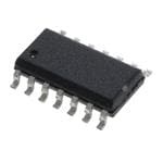
| 产品图片 |
|
| rohs | 符合RoHS无铅 / 符合限制有害物质指令(RoHS)规范要求 |
| 产品系列 | 接口 IC,RS-485接口IC,Exar SP3491EN-L- |
| 数据手册 | http://www.exar.com/Common/Content/Document.ashx?id=641 |
| 产品型号 | SP3491EN-L |
| PCN设计/规格 | |
| 产品种类 | RS-485接口IC |
| 供应商器件封装 | 14-SOIC |
| 关闭 | No |
| 其它名称 | 1016-1149-5 |
| 功能 | Transceiver |
| 包装 | 管件 |
| 协议 | RS485 |
| 双工 | 全 |
| 商标 | Exar |
| 安装类型 | 表面贴装 |
| 安装风格 | SMD/SMT |
| 封装 | Tube |
| 封装/外壳 | 14-SOIC(0.154",3.90mm 宽) |
| 封装/箱体 | SOIC-14 Narrow |
| 工作温度 | -40°C ~ 85°C |
| 工作温度范围 | - 40 C to + 85 C |
| 工作电源电压 | 3.3 V |
| 工厂包装数量 | 56 |
| 接收器滞后 | 25mV |
| 接收机数量 | 1 Receiver |
| 数据速率 | 10Mbps |
| 最大功率耗散 | 700 mW |
| 最大工作温度 | + 85 C |
| 最小工作温度 | - 40 C |
| 标准包装 | 56 |
| 激励器数量 | 1 Driver |
| 电压-电源 | 3 V ~ 3.6 V |
| 电源电流 | 1000 uA |
| 类型 | 收发器 |
| 系列 | SP3490/SP3491 |
| 输出类型 | 3-State |
| 驱动器/接收器数 | 1/1 |


PDF Datasheet 数据手册内容提取
SP3490 / SP3491 3.3V Low Power Full-Duplex RS-485 Transceivers with 10Mbps Data Rate Description FEATURES The SP3490 and SP3491 devices are 3.3V low power full-duplex ■■ Full-duplex RS-485 and RS-422 transceivers that meet the specifications of the RS-485 and RS-422 transceivers serial protocols. These devices are pin-to-pin compatible with the ■■ Operates from a single 3.3V supply MaxLinear SP490 and SP491 devices as well as popular industry ■■ Interoperable with 5.0V logic standards. The SP3490 and SP3491 feature MaxLinear’s BiCMOS ■■ Driver/receiver tri-state enable lines (SP3491) process, allowing low power operation without sacrificing performance. ■■ -7V to 12V common-mode input voltage The SP3490 and SP3491 meet the electrical specifications of the range RS-485 and RS-422 serial protocols up to 10Mbps under load. The ■■ ±200mV receiver input sensitivity SP3491 is identical to the SP3490 with the addition of driver and ■■ Allows up to 32 transceivers on the serial reciveiver tri-state enable lines. bus ■■ Compatability with LTC490 and SN75179 (SP3490) ■■ Compatability with LTC491 and SN75180 (SP3491) Ordering Information - Back Page Block Diagrams 1 1 14 VCC VCC NC 13 NC 8 12 A A 2 2 R R 7 R R 11 B B 3 REB 4 DE 6 10 Z Z 3 5 D D D D 5 Y 6 9 Y GND 4 7 8 GND GND NC SP3490 SP3491 REV 1.0.3 1/12
SP3490 / SP3491 Absolute Maximum Ratings Operating Conditions These are stress ratings only and functional operation of the Package Power Dissipation device at these ratings or any other above those indicated 8-pin NSOIC Ѳ ................................................128.4˚C/W JA in the operation sections of the specifications below is not implied. Exposure to absolute maximum rating conditions 14-pin NSOIC ѲJA ................................................88.2˚C/W for extended periods of time may affect reliability. V ...............................................................................6.0V CC ESD Rating Input Voltages Human Body Model (HBM) ..........................................±2kV Logic .....................................-0.3V to 6.0V Drivers ..................................-0.3V to 6.0V Receivers ...........................................±14V Output Voltages Drivers ...............................................±14V Receivers ..............................-0.3V to 6.0V Storage Temperature .................................-65˚C to +150˚C Maximum Junction Temperature, T ..........................125˚C J Power Dissipation 8-pin NSOIC ............................................................600mW (derate 6.90mW/°C above +70°C) 14-pin NSOIC .........................................................700mW (derate 8.33mW/°C above +70°C) Electrical Characteristics T = T to T and V = 3.3V ±5% unless otherwise noted. AMB MIN MAX CC PARAMETERS MIN. TYP. MAX. UNITS CONDITIONS SP3490 Driver DC Characteristics Differential output voltage Vcc V Unloaded; R = ∞Ω ; Figure 1 Differential output voltage 2 Vcc V With load; R = 50Ω (RS-422); Figure 1 Differential output voltage 1.5 Vcc V With load; R = 27Ω (RS-485); Figure 1 Change in magnitude of driver differential output voltage for 0.2 V R = 27Ω or R = 50Ω; Figure 1 complimentary states Driver common-mode output voltage 3 V R = 27Ω or R = 50Ω; Figure 1 Input high voltage 2.0 V Input low voltage 0.8 V Input current ±10 µA Driver short circuit current VOUT = HIGH ±250 mA -7V ≤ VO ≤ 12V; Figure 8 Driver short circuit current VOUT = LOW ±250 mA -7V ≤ VO ≤ 12V; Figure 8 SP3490 Driver AC Characteristics Maximum data rate 10 Mbps Driver input to output, tPLH 20 40 60 ns R = 27Ω, Figures 2 & 9 Driver input to output, tPHL 20 40 60 ns R = 27Ω, Figures 2 & 9 REV 1.0.3 2/12
SP3490 / SP3491 Electrical Characteristics (Continued) T = T to T and V = 3.3V ±5% unless otherwise noted. AMB MIN MAX CC PARAMETERS MIN. TYP. MAX. UNITS CONDITIONS SP3490 Driver AC Characteristics (Continued) Differential driver skew 2 ns |tPHL(Y)- tPLH(Y)|, |tPHL(Z)- tPLH(Z)|, Figures 2 and 9 Driver rise or fall time 5 20 ns From 10%-90%; Figures 3 and 10 SP3490 Receiver DC Characteristics Differential input threshold -0.2 0.2 Volts -7V ≤ VCM ≤ 12V Input hysteresis 25 mV VCM = 0V Output voltage HIGH Vcc-0.4 Volts VID = 200mV, IO = -1.5mA Output voltage LOW 0.4 Volts VID = -200mV, IO = 2.5mA Input resistance 12 15 kΩ -7V ≤ VCM ≤ 12V Input current (A, B); VIN = 12V 1.0 mA VIN = 12V Input current (A, B); VIN = -7V -0.8 mA VIN = -7V Short circuit current 60 mA 0V ≤ VO ≤ VCC SP3490 Receiver AC Characteristics Maximum data rate 10 Mbps Receiver input to output, tPLH 40 70 120 ns Figures 6 and 12 Receiver input to output, tPLH 85 ns TAMB = 25°C, Vcc = 3.3V, Figures 6 and 12 Receiver input to output, tPHL 40 70 120 ns Figures 6 and 12 Receiver input to output, tPHL 85 ns TAMB = 25°C, Vcc = 3.3V, Figures 6 and 12 Differential receiver skew 4 ns |tPHL(A)- tPLH(A)|, |tPHL(B)- tPLH(B)|, Figures 6 and 12 Power Requirements Supply Voltage 3.0 3.3 3.6 V Supply Current 1000 2000 µA D = 0V or VCC ESD Protection for D, R, A, B, Y and ±2 kV Human Body Model Z pins REV 1.0.3 3/12
SP3490 / SP3491 Electrical Characteristics, Continued T = T to T and V = 3.3V ±5% unless otherwise noted AMB MIN MAX CC PARAMETERS MIN. TYP. MAX. UNITS CONDITIONS SP3491 Driver DC Characteristics Differential output voltage Vcc V Unloaded; R = ∞Ω ; Figure 1 Differential output voltage 2 Vcc V With load; R = 50Ω (RS-422); Figure 1 Differential output voltage 1.5 Vcc V With load; R = 27Ω (RS-485); Figure 1 Change in magnitude of driver differential output voltage for 0.2 V R = 27Ω or R = 50Ω; Figure 1 complimentary states Driver common-mode output voltage 3 V R = 27Ω or R = 50Ω; Figure 1 Input high voltage 2.0 V Applies to DE, D, REB Input low voltage 0.8 V Applies to DE, D, REB Input current ±10 µA Applies to DE, D, REB Driver short circuit current VOUT = HIGH ±250 mA -7V ≤ VO ≤ 12V; Figure 8 Driver short circuit current VOUT = LOW ±250 mA -7V ≤ VO ≤ 12V; Figure 8 SP3491 Driver AC Characteristics Maximum data rate 10 Mbps Driver input to output, tPLH 20 40 60 ns Figures 2 & 9 Driver input to output, tPHL 20 40 60 ns Figures 2 & 9 Differential driver skew 2 ns |tPHL(Y)- tPLH(Y)|, |tPHL(Z)- tPLH(Z)|, Figures 2 and 9 Driver rise or fall time 5 20 ns From 10%-90%; Figures 3 and 10 Driver enable to output HIGH 52 120 ns Figures 4 and 11 Driver enable to output LOW 60 120 ns Figures 5 and 11 Driver disable from LOW 40 120 ns Figures 5 and 11 Driver disable from HIGH 60 120 ns Figures 4 and 11 REV 1.0.3 4/12
SP3490 / SP3491 Electrical Characteristics, Continued T = T to T and V = 3.3V ±5% unless otherwise noted AMB MIN MAX CC PARAMETERS MIN. TYP. MAX. UNITS CONDITIONS SP3491 Receiver DC Characteristics Differential input threshold -0.2 0.2 Volts -7V ≤ VCM ≤ 12V Input hysteresis 25 mV VCM = 0V Output voltage HIGH Vcc-0.4 Volts VID = 200mV, IO = -1.5mA Output voltage LOW 0.4 Volts VID = -200mV, IO = 2.5mA Three-State ( High Impedance) Output Current ±1 µA 0V ≤ VO ≤ Vcc; REB = Vcc Input resistance 12 15 kΩ -7V ≤ VCM ≤ 12V Input current (A, B); VIN = 12V 1.0 mA DVIEN == 01V2,V VCC = 0V or 3.6V, Input current (A, B); VIN = -7V -0.8 mA DVIEN == 0-7VV, VCC = 0V or 3.6V, Short circuit current 60 mA 0V ≤ VO ≤ VCC SP3491 Receiver AC Characteristics Maximum data rate 10 Mbps REB = 0V, DE = 0V Receiver input to output, tPLH 40 70 120 ns Figures 6 and 12 Receiver input to output, tPLH 85 ns TAMB = 25°C, Vcc = 3.3V, Figures 6 and 12 Receiver input to output, tPHL 40 70 120 ns Figures 6 and 12 Receiver input to output, tPHL 85 ns TAMB = 25°C, Vcc = 3.3V, Figures 6 and 12 Differential receiver skew 4 ns |tPHL(A)- tPLH(A)|, |tPHL(B)- tPLH(B)|, Figures 6 and 12 Receiver enable to output LOW 65 150 ns Figures 7 and 13; S1 Closed, S2 open Receiver enable to output HIGH 65 150 ns Figures 7 and 13; S2 Closed, S1 open Receiver disable from LOW 65 200 ns Figures 7 and 13; S1 Closed, S2 open Receiver disable from HIGH 65 200 ns Figures 7 and 13; S2 Closed, S1 open Power Requirements Supply voltage 3.0 3.6 V Supply current 1000 2000 µA REB, D = 0V or VCC; DE = VCC Supply current 800 1500 µA DE = 0V ESD protection for R, D, DE, REB, A, ±2 kV Human Body Model B, Y and Z pins REV 1.0.3 5/12
SP3490 / SP3491 Pin Functions 1 Pin Number Pin Name Description V CC 1 VCC Positive supply 3.00V < Vcc < 3.60V 8 2 A 2 R Receiver output R R 7 B 3 D Driver Input 4 GND Ground connection 6 5 Y Non-inverting driver output Z 3 6 Z Inverting driver output D D 5 7 B Inverting receiver Input Y 4 8 A Non-inverting receiver input GND SP3490 Pinout (Top View) 1 14 VCC Pin Number Pin Name Description NC 13 NC 1 NC No connect(1) 12 2 A 2 R Receiver output R R 11 B 3 REB Receiver output enable active LOW 3 REB 4 DE Driver output enable active HIGH 4 DE 10 5 D Driver input Z 5 D D 6 GND Ground connection 6 9 Y 7 GND Ground connection GND 7 8 GND NC 8 NC No connect(1) 9 Y Non-inverting driver output 10 Z Inverting driver output SP3491 11 B Inverting receiver input Pinout (Top View) 12 A Non-Inverting receiver input 13 NC No connect(1) 14 VCC Positive supply 3.00V < Vcc < 3.60V Note: 1. Not internally bonded, can be connected to Vcc without harm. REV 1.0.3 6/12
SP3490 / SP3491 Test Circuits VDM R RL = 27Ω S1 D OUT V D OD GENERATOR (NOTE 1) 50Ω CL = 15pF R V VCC (NOTE 2) Vcc OC VOM = V O H 2 + V O L ≈ 1.5V Figure 1: Driver DC Test Load Circuit Figure 2: Driver Propagation Delay Test Circuit S1 D OUT D CL 6R0L Ω= OUT CL = 50pF RL = 110Ω (NOTE 2) GENERATOR GENERATOR (NOTE 1) 50Ω (NOTE 1) 50Ω VCC CL = 15pF (NOTE 2) VOM = V O H 2 + V O L ≈ 1.5V Figure 3: Driver Differential Output Delay and Figure 4: Driver Enable and Disable Timing Circuit, Transition Time Circuit. Output High VCC OUT RL = 110Ω VID R S1 GENERATOR 50Ω 0V OR 3V D OUT (NOTE 1) CL = 15pF (NOTE 2) CL = 50pF (NOTE 2) GENERATOR (NOTE 1) 50Ω 1.5V VOM = VCC 0V 2 Figure 5: Driver Enable and Disable Timing Circuit, Figure 6: Receiver Propagation Delay Test Circuit Output Low S1 S3 1.5V 1k VCC -1.5V VID R S2 DE = 0 or Vcc A/Y IOS D DI = 0 or Vcc D CL = 15pF (NOTE 2) 100Ω B/Z GENERATOR (NOTE 1) 50Ω -7V to +12V V Figure 7: Receiver Enable and Disable Timing Circuit Figure 8: Driver Short Circuit Current Limit Test REV 1.0.3 7/12
SP3490 / SP3491 Switching Waveforms 3V 3V INPUT 1.5V 1.5V IN 1.5V 1.5V 0V VOH tPLH tPHL 0V tDO1 tDO2 Y OUTPUT VOM VOM VOL 2.0V 90% 90% tPHL tPLH 50% 50% VOH OUT 10% 10% Z OUTPUT VOM VOM -2.0V VOL tTD tTD VOM = VOH 2+ VOL ≈ 1.5V Figure 9: Driver Propagation Delay Waveforms Figure 10: Driver Differential Output Delay and Transition Time Waveforms 3V DE 1.5V 1.5V 3V 0V tPZH tPHZ INPUT 1.5V 1.5V VOH 0.25V OUTPUT VOM 0V HIGH 0V t t RPLH RPHL V CC OUTPUT VCC tPZL tPLZ OUTPUT VOM VOM LOW VOM 0.25V 0V VOL V VOM = VOH 2+ VOL ≈ 1.5V VOM = 2CC Figure 11: Driver Enable and Disable Timing Waveforms Figure 12: Receiver Propagation Delay Waveforms S1 is open S1 is closed S2 is closed S2 is open S3 = 1.5V S3 = -1.5V 3V 3V REB 1.5V 1.5V REB 1.5V 1.5V 0V 0V tPRHZ ttPRZH tPRLZ ttPPRRZSLL PRSH VOH 10% VCC OUTPUT 1.5V OUTPUT 1.5V 10% 0V VOL Figure 13: Receiver Enable and Disable Waveforms NOTES 1. The input pulse is supplied by a generator with the following characteristics: PRR = 250kHz, 50% duty cycle, tR < 6.0ns, ZO = 50Ω. 2. CL includes probe and stray capacitance. REV 1.0.3 8/12
SP3490 / SP3491 Description The SP3490 and SP3491 are two members in the family Receivers of 3.3V low power full-duplex transceivers that meet the The receivers of the SP3490 and SP3491 have differential electrical specifications of the RS-485 and RS-422 serial inputs with an input sensitivity of ±200mV. Input impedance protocols. These devices are pin-to-pin compatible with the of the receivers is typically 15kΩ (12kΩ minimum). A wide MaxLinear SP490 and SP491 devices as well as popular common mode range of -7V to 12V allows for large ground industry standards. The SP3490 and SP3491 feature potential differences between systems. The receivers for MaxLinear’s BiCMOS process allowing low power operation both the SP3490 and SP3491 are equipped with a fail- without sacrificing performance. safe feature that guarantees the receiver output will be in a HIGH state when the input is left unconnected. The RS-485 standard is ideal for multi-drop applications and for long-distance interfaces. RS-485 allows up to 32 drivers The receiver of the SP3491 has a enable control line which and 32 receivers to be connected to a data bus, making is active LOW. A logic LOW on REB (pin 3) of the SP3491 it an ideal choice for multi-drop applications. Since the will enable the differential receiver. A logic HIGH on REB cabling can be as long as 4,000 feet, RS-485 transceivers (pin 3) of the SP3491 will tri-state the receiver. are equipped with a wide (-7V to 12V) common mode range to accommodate ground potential differences. Because RS-485 is a differential interface, data is virtually immune to noise in the transmission line. Drivers The drivers for both the SP3490 and SP3491 have differential outputs. The typical voltage output swing with no load will be 0 volts to Vcc. With worst case loading of 54Ω across the differential outputs, the drivers can maintain greater than 1.5V voltage levels. The driver of the SP3491 has a driver enable control line which is active HIGH. A logic HIGH on DE (pin 4) of the SP3491 will enable the differential driver outputs. A logic LOW on the DE (pin 4) will tri-state the driver outputs. The SP3490 does not have a driver enable. REV 1.0.3 9/12
SP3490 / SP3491 Mechanical Dimensions NSOIC8 Top View Side View Front View Drawing No: POD-00000108 Revision: A REV 1.0.3 10/12
SP3490 / SP3491 Mechanical Dimensions NSOIC14 Top View Side View Front View Drawing No: POD-00000109 Revision: A REV 1.0.3 11/12
SP3490 / SP3491 Ordering Information(1) Part Number Operating Temperature Range Lead-Free Package Packaging Method SP3490CN-L/TR 0°C to 70°C Reel SP3490EN-L 8-pin NSOIC Tube -40°C to 85°C SP3490EN-L/TR Reel SP3491CN-L Yes(2) Tube 0°C to 70°C SP3491CN-L/TR Reel 14-pin NSOIC SP3491EN-L Tube -40°C to 85°C SP3491EN-L/TR Reel NOTE: 1. Refer to www.exar.com/SP3490 and www.exar.com/SP3491 for most up-to-date Ordering Information. 2. Visit www.exar.com for additional information on Environmental Rating. Revision History Revision Date Description 10/11/02 -- Legacy Sipex Datasheet Convert to Exar Format. Update ordering information as a result of discontinued Lead type 06/08/10 1.0.0 package options per PDN 081126-01. Change revision to 1.0.0. Add new Figure 8 - Driver Short Circuit Current Limit Test Circuit 9/14/10 1.0.1 Correct package type for SP3491 options in ordering table from 8 pin NSOIC to 14 pin NSOIC Add ESD protection levels of +/-2kV. Remove SP3490 Supply Current rating for DE = 0V (No 10/27/10 1.0.2 driver enable for SP3490). Update to MaxLinear logo. Update pin description table to include note on NC pin. Remove GND from Differential Output Voltage min (page 2 and 4). Added maximum junction 09/06/17 1.0.3 temperature, package power dissipation and ESD rating. Update format and ordering information table. Corporate Headquarters: High Performance Analog: 5966 La Place Court 48720 Kato Road Suite 100 Fremont, CA 94538 Carlsbad, CA 92008 Tel.: +1 (510) 668-7000 Tel.:+1 (760) 692-0711 Fax: +1 (510) 668-7001 Fax: +1 (760) 444-8598 Email: serialtechsupport@exar.com www.maxlinear.com www.exar.com The content of this document is furnished for informational use only, is subject to change without notice, and should not be construed as a commitment by MaxLinear, Inc.. MaxLinear, Inc. assumes no responsibility or liability for any errors or inaccuracies that may appear in the informational content contained in this guide. Complying with all applicable copyright laws is the responsibility of the user. Without limiting the rights under copyright, no part of this document may be reproduced into, stored in, or introduced into a retrieval system, or transmitted in any form or by any means (electronic, mechanical, photocopying, recording, or otherwise), or for any purpose, without the express written permission of MaxLinear, Inc. Maxlinear, Inc. does not recommend the use of any of its products in life support applications where the failure or malfunction of the product can reasonably be expected to cause failure of the life support system or to significantly affect its safety or effectiveness. Products are not authorized for use in such applications unless MaxLinear, Inc. receives, in writing, assurances to its satisfaction that: (a) the risk of injury or damage has been minimized; (b) the user assumes all such risks; (c) potential liability of MaxLinear, Inc. is adequately protected under the circumstances. MaxLinear, Inc. may have patents, patent applications, trademarks, copyrights, or other intellectual property rights covering subject matter in this document. Except as expressly provided in any written license agreement from MaxLinear, Inc., the furnishing of this document does not give you any license to these patents, trademarks, copyrights, or other intellectual property. Company and product names may be registered trademarks or trademarks of the respective owners with which they are associated. © 2017 MaxLinear, Inc. All rights reserved SP3490_SP3491_DS_090617 REV 1.0.3 12/12
Mouser Electronics Authorized Distributor Click to View Pricing, Inventory, Delivery & Lifecycle Information: E xar: SP3490CN-L SP3490EN-L SP3491EN-L SP3491CN-L SP3490CN-L/TR SP3490EN-L/TR SP3491CN-L/TR SP3491EN-L/TR