
 Datasheet下载
- 型号: SM-3TW103
- 制造商: Copal Electronics Inc
- 库位|库存: xxxx|xxxx
- 要求:
| 数量阶梯 | 香港交货 | 国内含税 |
| +xxxx | $xxxx | ¥xxxx |
查看当月历史价格
查看今年历史价格
SM-3TW103产品简介:
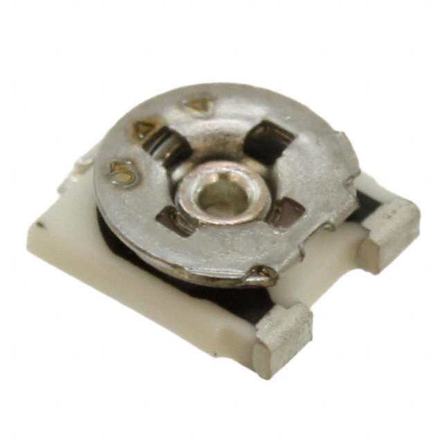
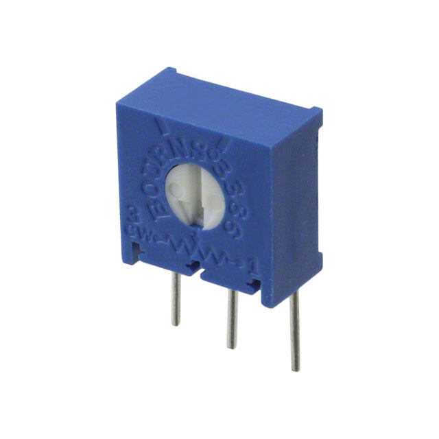
ICGOO电子元器件商城为您提供SM-3TW103由Copal Electronics Inc设计生产,在icgoo商城现货销售,并且可以通过原厂、代理商等渠道进行代购。 SM-3TW103价格参考。Copal Electronics IncSM-3TW103封装/规格:微调电位计, 10 kOhms 0.125W,1/8W J 引线 表面贴装 微调电位器 金属陶瓷 11 匝 顶部调节。您可以下载SM-3TW103参考资料、Datasheet数据手册功能说明书,资料中有SM-3TW103 详细功能的应用电路图电压和使用方法及教程。
Nidec Copal Electronics品牌的微调电位计型号SM-3TW103,是一种小型、高精度的可调电阻元件,主要用于需要精确调节电压或电流的电子电路中。以下是其典型的应用场景:

1. 音频设备
   在音频设备中,SM-3TW103可用于调节音量、平衡或音调控制。例如,在混音器、功放或耳机放大器中,它能够提供精细的电阻调整,以满足用户对声音质量的需求。

2. 电源管理
   该型号适用于各种电源电路,如直流稳压电源或开关电源中的输出电压微调。通过调整电位计的阻值,可以精确设置输出电压水平,确保下游设备正常工作。

3. 工业控制
   在工业自动化领域,SM-3TW103可用于校准传感器、变送器或其他测量仪器的输出信号。例如,在温度控制器、压力传感器等设备中,它可以用来校正偏差,提高测量精度。

4. 医疗设备
   医疗仪器对精度要求极高,SM-3TW103可应用于心率监测仪、血压计或血糖仪等设备中,用于校准内部电路参数,确保数据准确性。

5. 通信设备
   在无线通信模块或射频电路中,该电位计可用于调节增益、偏置电压或频率响应,从而优化信号传输性能。

6. 测试与测量仪器
   在示波器、万用表或多通道数据采集系统中,SM-3TW103可用于校准基准电压或灵敏度设置,保证测量结果的一致性和可靠性。

7. 消费电子产品
   某些便携式设备(如电子玩具、遥控器)可能需要微调某些功能参数,此时该型号电位计可作为出厂前校准工具使用。

总结来说,SM-3TW103因其体积小巧、性能稳定和易于安装的特点,广泛应用于需要精密电阻调节的各种电子设备中,尤其适合那些对成本敏感但又需要一定调节范围的场景。
| 参数 | 数值 |
| 产品目录 | |
| 描述 | TRIMMER 10K OHM 0.125W SMD |
| 产品分类 | |
| 品牌 | Copal Electronics Inc |
| 数据手册 | |
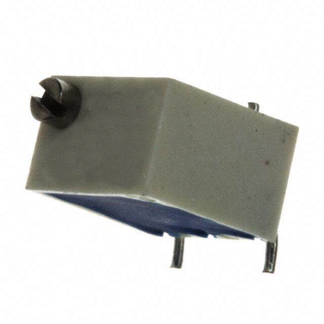
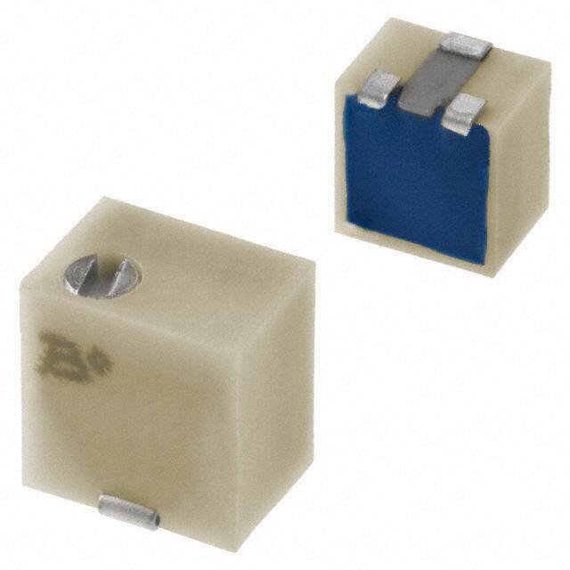
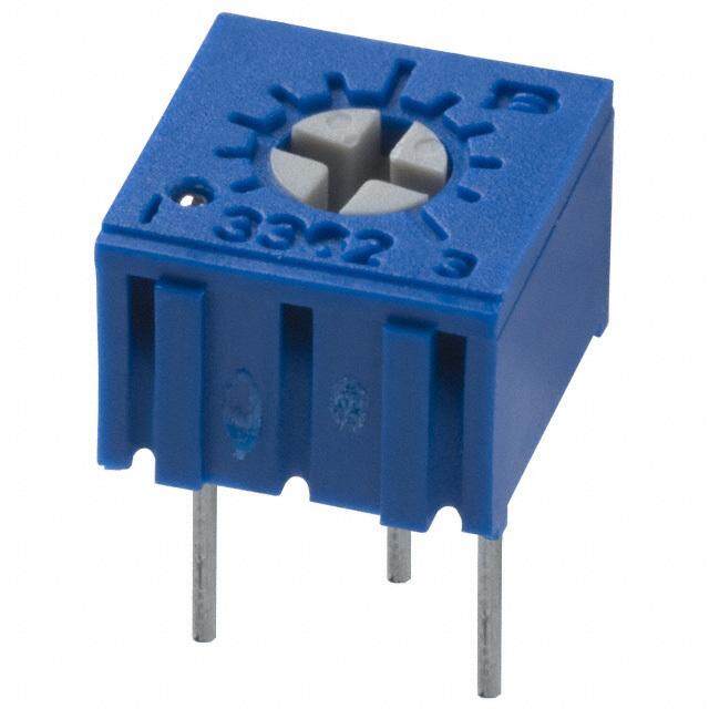
| 产品图片 |
|
| 产品型号 | SM-3TW103 |
| rohs | 无铅 / 符合限制有害物质指令(RoHS)规范要求 |
| 产品系列 | SM3 |
| 产品目录绘图 |
|
| 产品目录页面 | |
| 其它名称 | SM-3TW103DKR |
| 功率(W) | 0.125W,1/8W |
| 包装 | Digi-Reel® |
| 圈数 | 11 |
| 大小/尺寸 | 矩形 - 0.154" x 0.126" 表面 x 0.154" 高 (3.90mm x 3.20mm x 3.90mm) |
| 安装类型 | 表面贴装 |
| 容差 | ±20% |
| 标准包装 | 1 |
| 温度系数 | ±100ppm/°C |
| 特色产品 | http://www.digikey.com/product-highlights/cn/zh/copal-electronics-sm-3-31-series-smd-cermet-trimmers/3730 |
| 电阻(Ω) | 10k |
| 电阻材料 | 金属陶瓷 |
| 端子类型 | J 引线 |
| 调节类型 | 顶部调节 |


PDF Datasheet 数据手册内容提取
SM-3/31 SURFACE MOUNT CERMET TRIMMERS RoHS compliant INTERNAL STRUCTURE 1 9 2 8 3 4 5 7 6 Part name Material Flammability ■ FEATURES 1 Housing Polyphenylenesulphide UL94V-0 ● RoHS compliant 2 Base element Ceramic ● Fine adjustment is possible ● Automatic mounting is possible (Taping) 3 Electrode Ag-Pd cermet ● Reflow soldering is possible ● Sealed construction (Washable: Refer to page 698.) 4 Resistive element RuO2 cermet — 5 Adhesive Epoxy 6 Wiper Multi metal alloy 7 Terminal pin Copper alloy, Sn-Cu-plated 8 Rotor gear Polyamide UL94V-0 9 Shaft Brass, Nickel-plated — ■ PART NUMBER DESIGNATION S M - 3 □ T W 1 k Ω ( 1 0 2 ) Series name Resistance code Electrical turn Resistance value Blank:11 turns 1:5 turns Product shape (Shape of terminal) Form of packaging A, W:J-hook T:Taping (Reel) B:Gull wing Blank:Bulk in plastic bag ※Please refer to the LIST OF PART NUMBERS when placing orders.
SM-3/31 SURFACE MOUNT TRIMMERS ■ LIST OF PART NUMBERS 〈Nominal resistance values〉 Adjustment Form of packaging 50 Ω 100 Ω 200 Ω 500 Ω 1 kΩ 2 kΩ 5 kΩ 10 kΩ Electrical turns Shape of terminal position Taping (reel) Plastic bag 20 kΩ 50 kΩ 100 kΩ 200 kΩ 500 kΩ 1 MΩ 2 MΩ Fig. 1 Top adjustment W (J-hook) SM-3TW SM-3W 11 A (J-hook) SM-3TA SM-3A Side adjustment B (Gull wing) SM-3TB SM-3B Top adjustment W (J-hook) SM-31TW SM-31W 5 A (J-hook) SM-31TA SM-31A Side adjustment ※ The above part numbers are all available with the respective combination B (Gull wing) SM-31TB SM-31B of <Nominal resistance values> (Fig. 1). ※ Verify the above part numbers when placing orders. Pieces in package 500 pcs./reel 50 pcs./pack ※ Taping specification is not sold separately and must be purchased in reel units. ■ ELECTRICAL CHARACTERISTICS ■ MECHANICAL CHARACTERISTICS Nominal resistance range 50 Ω ~ 2 MΩ Operating torque 5 mN·m {51 gf·cm} maximum Resistance tolerance ± 20 % Mechanical stop Clutch action Power ratings 0.125 W (70 °C) 0 W (150 °C) Rotational life 200 cycles [ΔR/R ≦ ± (2 Ω +3 %)] Resistance law (B) Thrust to shaft 5 N {0.51 kgf} minimum Linear law Maximum input voltage DC200 V or power rating, whichever is smaller Solderability 245 ± 3 °C, 2 ~ 3 s Maximum wiper current 100 mA or power rating, whichever is smaller Shear (Adhesion) 5 N {0.51 kgf} 10 s Effective electrical turn 11 turns (SM-3) / 5 turns (SM-31) Substrate bending Width 90 mm, bend 3 mm, 5 s, 1 time End resistance 1 % or 3 Ω, whichever is greater Pull-off strength 5 N {0.51 kgf} 10 s C.R.V. 3 % or 3 Ω, whichever is greater { }:Reference only Operating temp. range −65 ~ 150 °C Temp. coefficient ±100 10-6/°C maximum ■ ENVIRONMENTAL CHARACTERISTICS Insulation resistance 100 MΩ minimum (DC500 V) Test item Test conditions Specifications Dielectric strength AC600 V, 60 s [ΔR/R ≦ 2 %] Thermal shock−65 ~ 150 °C (0.5 h), 5 cycles [S.S. ≦ 2 %] Net weight Approx. 0.10 g Humidity −10 ~ 65 °C (80 ~ 98 %), [ΔR/R ≦ 3 %] 10 cycles, 240 h 981 m/s2, 6 ms Shock 6 directions for 3 times each 〈Reflow profile for soldering heat evaluation〉 [ΔR/R ≦ 1 %] (Amplitude) 1.52 mm or [S.S. ≦ 1 %] Vibration (Acceleration) 196 m/s2, (℃) 10 ~ 2000 Hz, 3 directions, 12 times each 250 Peak : 250+ 50℃ [ΔR/R ≦ 3 %] Load life 70 °C, 0.125 W, 1000 h Over 230 ℃ [S.S. ≦ 2 %] [ΔR/R ≦ 2 %] e 200 Pre Heating Zone Low temp. operation −65 °C, 2 h [S.S. ≦ 2 %] atur 180 ℃ High temp. exposure 150 °C, 250 h [ΔR/R ≦ 3 %] er 150 150 ℃ [S.S. ≦ 2 %] p Tem 90 ± 30 s Immersion seal 85 °C, 60 s (No conNtinou leoaukss bubbles) 100 30 ± 10 s Reflow : Peak temperature 255 °C 50 Soldering Zone Soldering heat (Please refer to the profile below.) [ΔR/R ≦ 1 %] Heating time Manual soldering:350 ± 10 °C, 3 ~ 4 s Reflow : two times maximum ΔR/R:Change in total resistance S.S. :Setting stability
SM-3/31 SURFACE MOUNT TRIMMERS ■ MAXIMUM INPUT RATINGS Nominal resistance values (Ω) Resistance code Maximum input voltage (V) Maximum wiper current (mA) 50 500 2.50 50.0 100 101 3.53 35.4 200 201 5.00 25.0 500 501 7.91 15.8 1 k 102 11.2 11.2 2 k 202 15.8 7.91 5 k 502 25.0 5.00 10 k 103 35.4 3.54 20 k 203 50.0 2.50 50 k 503 79.1 1.58 100 k 104 112 1.12 200 k 204 158 0.79 500 k 504 200 0.40 1 M 105 200 0.20 2 M 205 200 0.10 ■ RECOMMENDED P.C.B. PAD OUTLINE DIMENSIONS ● SM-3W/31W ● SM-3A/31A ● SM-3B/31B (Unit : mm) 1.3 1.3 1.3 1.3 6 2 1. 6 1. 3 1. 2 3.1 0 2.43 0 4 0 4.4 0 6 6 1. 1. 6 1. 0.9 0.9 2 2.8 2.8 0.9 2.8 0.9 ※Also available to place as the 2.8 above. Note) The zero point is the center of mounting. ■ OUTLINE DIMENSIONS Unless otherwise specified, tolerance : ± 0.3 (Unit : mm) ● SM-3W/31W Top adjustment 1 3 CW rotation 2 Resistance code & Production date code 1 0.8 ※Note the terminal position. 2 2.8 6 1 3.9 0. 0.8 2.3 3.9 3 3.2 4.2 ΔR/R:Change in total resistance 3.5 0.4W × 1.3L × 0.3D S.S. :Setting stability
SM-3/31 SURFACE MOUNT TRIMMERS ■ OUTLINE DIMENSIONS Unless otherwise specified, tolerance : ± 0.3 (Unit : mm) ● SM-3A/31A ● SM-3B/31B Side adjustment Side adjustment 1 3 CW rotation Resistance code & Resistance code & Production date code 2 Production date code ※Note the terminal position. 5 5 2. 2. 0.4W × 1.3L × 0.3D 0.4W × 1.3L × 0.3D 3.9 3.4 3.9 3.4 1 2 3 – 0.8 1 2 8 0. – 4.4 3.9 3 5.3 3.9 2 – 0.6 3 1 2 – 0.6 2.8 3 1 2.8 ■ PACKAGING SPECIFICATIONS <Taping packaging specifications> ● Taping version is packaged in 500 pcs. per reel. Maximum number of consecutive missing pieces = 2 Orders will be accepted for units of 500 pcs., i.e., 500, Leader length and reel dimension are shown in the dia- 1000, 1500 pcs., etc. grams below. ● Taping version is boxed with one reel. ● EMBOSSED TAPE DIMENSIONS ● REEL DIMENSIONS (Conforms to JIS C 0806-3) (In accordance with EIAJ ET-7200A) (Unit: mm) Empty Filled Empty 13+ 10 End Head 21±0.8 40 mm miDn.irection of feed 20 pitches minL.eader 2±0.5 +160 0 400 mm min. 13±0.2 180 – 01.5 15.4±1
SM-3/31 SURFACE MOUNT TRIMMERS ● SM-3TW/31TW 4 ± 0.1 2 ± 0.05 0.1 ± 0.4 ± 0.1 φ1.5 0+0.1 A 3 1.75 I(nSsMta-l3laWtio)n example 5 0 0. ± 5.5 +0.3–0.1 2 1 2 A 1 8 ± 0.1 4.7 Cross section A-A ● SM-3TA/31TA 1 4 ± 0.1 0. ± 0.4 ± 0.1 φ1.5 0+0.1 2 ± 0.05A 3 1.75 (InSsMta-l3laAt)ion example 1 5 0 0. ± 5.5 +0.32–0.1 1 A 2 8 ± 0.1 3.9 Cross section A-A ● SM-3TB/31TB 1 4 ± 0.1 0. ± 0.4 ± 0.1 φ1.5 0+0.1 2 ± 0.05A 3 1.75 (InSsMta-l3laBt)ion example 1 5 0 0. ± 5.5 +0.32–0.1 1 A 3.9 Cross section A-A 2 8 ± 0.1 <Bulk pack specifications> ● Unit of bulk in a plastic bag is 50 pcs. per pack. ● Boxing of bulk in a plastic bag is performed with 200 pcs. per box.