ICGOO在线商城 > 电阻器 > 芯片电阻 - 表面安装 > RT0603DRD07825RL

 Datasheet下载
- 型号: RT0603DRD07825RL
- 制造商: YAGEO AMERICA CORPORATION
- 库位|库存: xxxx|xxxx
- 要求:
| 数量阶梯 | 香港交货 | 国内含税 |
| +xxxx | $xxxx | ¥xxxx |
查看当月历史价格
查看今年历史价格
RT0603DRD07825RL产品简介:
ICGOO电子元器件商城为您提供RT0603DRD07825RL由YAGEO AMERICA CORPORATION设计生产,在icgoo商城现货销售,并且可以通过原厂、代理商等渠道进行代购。 RT0603DRD07825RL价格参考。YAGEO AMERICA CORPORATIONRT0603DRD07825RL封装/规格:芯片电阻 - 表面安装, 825 Ohms ±0.5% 0.1W,1/10W 薄膜 芯片电阻 0603(1608 公制) 薄膜。您可以下载RT0603DRD07825RL参考资料、Datasheet数据手册功能说明书,资料中有RT0603DRD07825RL 详细功能的应用电路图电压和使用方法及教程。
Yageo品牌的RT0603DRD07825RL是一款表面安装的芯片电阻,具有广泛的电子应用。该型号的电阻具有高精度、低温度系数和良好的稳定性,适用于对性能要求较高的电路设计。

应用场景:

1. 消费电子设备:如智能手机、平板电脑、笔记本电脑等。这类设备需要高精度的电阻来确保信号完整性,特别是在电源管理、信号调理和滤波电路中,RT0603DRD07825RL能够提供稳定的电阻值,保证设备的正常运行。

2. 通信设备:在无线通信模块、路由器、调制解调器等设备中,电阻用于匹配阻抗、分压和电流限制等功能。该型号电阻的小尺寸(0603封装)使其适合于紧凑型设计,同时其高精度特性有助于提高通信质量。

3. 工业自动化:在工业控制系统中,如PLC(可编程逻辑控制器)、传感器接口和驱动电路中,电阻用于稳定电压和电流,确保系统的可靠性和精度。RT0603DRD07825RL的高可靠性使其能够在恶劣的工业环境中长期稳定工作。

4. 汽车电子:在车载电子系统中,如发动机控制单元(ECU)、车载娱乐系统、传感器网络等,电阻用于信号调理和保护电路。由于汽车环境的特殊性,该型号电阻的宽温度范围和高稳定性使其成为理想选择。

5. 医疗设备:如心电图机、血压计、血糖仪等医疗仪器中,电阻用于信号放大、滤波和保护电路。高精度和稳定的电阻特性对于确保测量结果的准确性至关重要。

6. 电源管理:在开关电源、线性稳压器等电源管理电路中,电阻用于设置反馈电压、电流限制和温度补偿等功能。RT0603DRD07825RL的低温度系数有助于保持电源输出的稳定性。

总之,Yageo的RT0603DRD07825RL芯片电阻凭借其高精度、小尺寸和高可靠性,广泛应用于各种电子设备中,尤其是在对性能和稳定性有较高要求的场合。
| 参数 | 数值 |
| 产品目录 | |
| 描述 | RES 825 OHM 1/10W .5% 0603 SMD |
| 产品分类 | |
| 品牌 | Yageo |
| 数据手册 | |
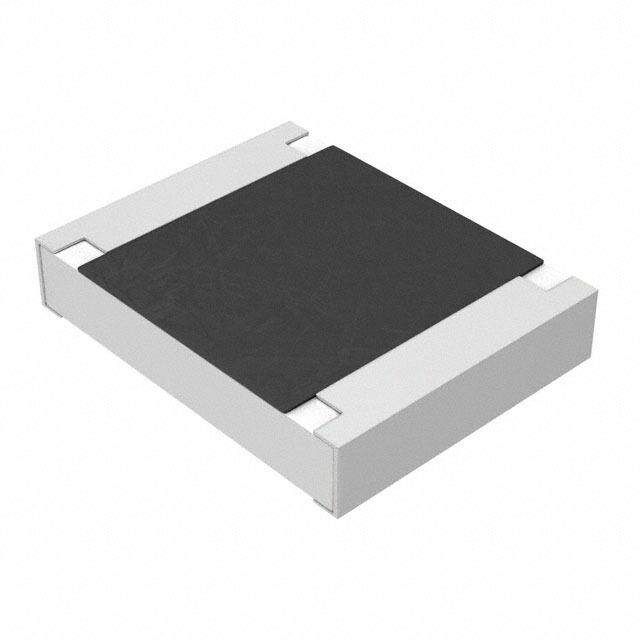
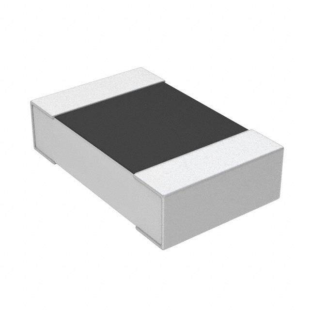
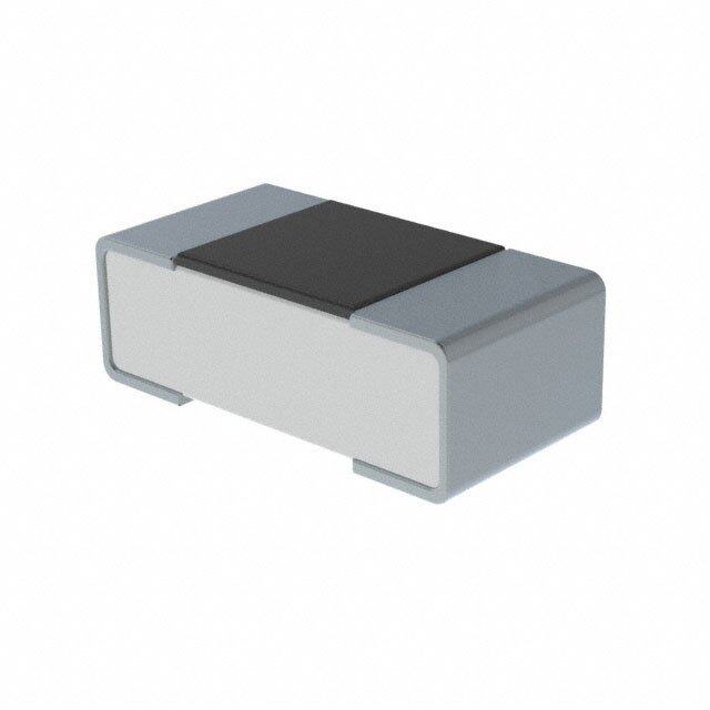
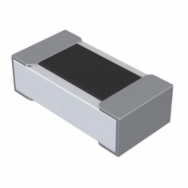
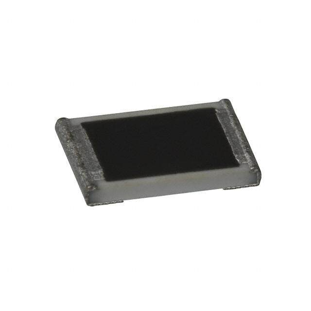
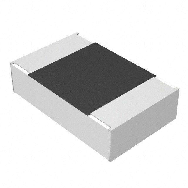
| 产品图片 |
|
| 产品型号 | RT0603DRD07825RL |
| rohs | 无铅 / 符合限制有害物质指令(RoHS)规范要求 |
| 产品系列 | RT |
| 产品培训模块 | http://www.digikey.cn/PTM/IndividualPTM.page?site=cn&lang=zhs&ptm=4919 |
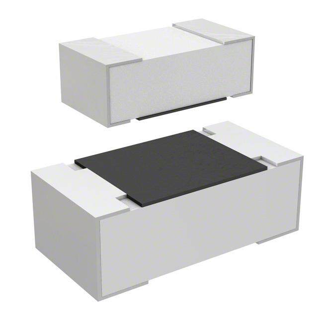
| 产品目录绘图 |
|
| 产品目录页面 | |
| 供应商器件封装 | 0603 |
| 其它名称 | 311-825DCT |
| 功率(W) | 0.1W,1/10W |
| 包装 | 剪切带 (CT) |
| 大小/尺寸 | 0.063" 长 x 0.031" 宽(1.60mm x 0.80mm) |
| 容差 | ±0.5% |
| 封装/外壳 | 0603(1608 公制) |
| 工作温度 | -55°C ~ 125°C |
| 成分 | |
| 标准包装 | 1 |
| 温度系数 | ±25ppm/°C |
| 特性 | - |
| 特色产品 | http://www.digikey.com/cn/zh/ph/Yageo/RTSeries.htmlhttp://www.digikey.com/product-highlights/cn/zh/thin-film-chip-resistors/2445 |
| 电阻(Ω) | 825 |
| 端子数 | 2 |
| 高度 | 0.022"(0.55mm) |


PDF Datasheet 数据手册内容提取
DATA SHEET THIN FILM CHIP RESISTORS High precision - high stability RT series 0.01% TO 1%, TCR 5 TO 50 sizes 0201/0402/0603/0805/1206/ 1210/2010/2512 RoHS compliant 9 V. 7 1 0 2 2, 1 r e b m e t p e S – n o ti a c cifi e p s t c u d o r P
Product specification 2 C hip Resistor Surface Mount R T SER IES 0 201 to 2512 (RoHS Comp liant) 9 SCOPE ORDERING INFORMATION - GLOBAL PART NUMBER & 12NC This specifica tion describes RT Both part numbers are identified by the series, size, tolerance, packing series high pre cision - high stability type, temperature coefficient, taping reel and resistance value. chip resistors with lead-free YYAAGGEEOO BBRRAANNDD oorrddeerriinngg ccooddee terminations made by thin film GLOBAL PART NUMBER (PREFERRED) process. RT XXXX F X X XX XXXX L (1) (2) (3) (4) (5) (6) (7) APPLICATIONS (1) SIZE Converters 0201/ 0402 / 0603 / 0805 / 1206 / 1210 / 2010 / 2512 Printing equipment (2) TOLERANCE Server board L = ±0.01% Telecom P = ±0.02% Consumer W = ±0.05% B = ±0.1% FEATURES C = ±0.25% Halogen Free Epoxy D = ±0.5% RoHS compliant F = ±1% Reducing environmentally (3) PACKAGING TYPE hazardous wastes R = Paper/PE taping reel K = Embossed taping reel High component and equipment reliability (4) TEMPERATURE COEFFICIENT OF RESISTANCE Saving of PCB space A = 5 ppm/°C None forbidden-materials used B = 10 ppm/°C in products/production C = 15 ppm/°C D = 25 ppm/°C E = 50 ppm/°C (5) TAPING REEL 07 = 7 inch dia. Reel 10 = 10 inch dia. Reel 13 = 13 inch dia. Reel (6) RESISTANCE VALUE There are 2~4 digits indicated the resistor value. Letter R/K/M is decimal point. Detailed resistance rules show in table of “Resistance rule of global part number”. (7) DEFAULT CODE Letter L is system default code for order only (Note) Resistance rule of global part ORDERING EXAMPLE number The ordering code of a RT0603 Resistance code rule Examp le chip resistor, TC 50 value 56 Ω 1R = 1 Ω XRXX with ±0.5% tolerance, supplied in 1R5 = 1.5 Ω (1 to 9.76 Ω) 7-inch tape reel is: 9R76 = 9.76 Ω RT0603DRE0756RL. XXRX 10R = 10 Ω (10 to 97.6 Ω) 97R6 = 97.6 Ω NOTE XXXR 100R = 100 Ω 1. All our RSMD products meet RoHS (100 to 976 Ω) compliant and Halogen Free. "LFP" of XKXX 1K = 1,000 Ω the internal 2D reel label mentions (1 to 9.76 KΩ) 9K76 = 9760 Ω "Lead Free Process" 2. On customized label, "LFP" or XMXX 1M = 1,000,000 Ω specific symbol can be printed (1 to 9.76 MΩ) 9M76= 9,760,000 Ω www.yageo.com Sep. 12, 2017 V.9
Product specification 3 C hip Resistor Surface Mount R T SER IES 0 201 to 2512 (RoHS Comp liant) 9 PPHHYYCCOOMMPP BBR RAANNDD oorrddeerriinngg ccooddeess B oth GLOBA L PART NUMBER (preferred) and 12NC (traditional) codes are acceptable to order Phycomp b rand produc ts. For matching traditional types with size codes, please refer to “Comparison table of traditional t ypes and sizes”. GLOBAL PART NUMBER (PREFERRED) For detailed information of GLOBAL PART NUMBER and ordering example, please refer to page 2. 12NC CODE 2390 X XX X XXXX L (1) (2) (3) (4) (5) (6) Comparison table of traditional START TCR (2) PACKING CODE TOL . (4) RESISTANCE DEFAULT types and sizes CODE WITH (1) (ppm/°C) BY SIZE (inch) (3) (%) RANGE TF X X X (NOTE) (1) (2) (3) (4) 2390 8 = ±10 0402: 07 = 7'' reel 7 = ±1 The remaining 4 digits Letter L is START SIZE TCR TOL. represent the resistance system 7 = ±15 47 = 13'' reel 6 = ±0.5 WITH CODE (ppm/°C) (%) value with the last digit default 6 = ±25 0603: 04 = 7'' reel 5 = ±0.25 TF 3 = 0402 4 = ±10 0 = ±1 indicating the multiplier code for 4 = ±50 24 = 10'' reel 4 = ±0.1 as shown in the table of order only 2 = 0603 3 = ±15 1 = ±0.5 44 = 13'' reel 3 = ±0.05 “Last digit of 12NC”. (Note) 1 = 0805 1 = ±25 2 = ±0.25 0805: 01 = 7'' reel 0402: 4.7Ω ≤ R ≤ 240KΩ 0 = 1206 2 = ±50 3 = ±0.1 41 = 13'' reel 0603: 1 Ω ≤ R ≤ 1MΩ 5 = 1210 4 = ±0.05 1206: 11 = 7'' reel 0805: 1Ω ≤ R ≤ 1.5 MΩ 7 = 2010 51 = 13'' reel 1206: 1Ω ≤ R ≤ 1.5 MΩ 6 = 2512 1210: 12 = 7'' reel 1210: 4.7Ω ≤ R ≤ 1 MΩ Example: 52 = 13'' reel 2010: 4.7Ω ≤ R ≤ 1 MΩ TF321 = RT0402, TC50, ±0.5% tolerance 2010: 15 = 7'' reel 2512: 4.7Ω ≤ R ≤ 1 MΩ 2512: 18 = 7'' reel Resistance decade (3) Last digit 1 to 9.76 Ω 8 10 to 97.6 Ω 9 100 to 976 Ω 1 1 to 9.76 kΩ 2 Exceptions to above packing code definitions: 10 to 97.6 kΩ 3 0805 TC50 with 1%, supplied in 13" reel, the packing code is 02. 100 to 976 kΩ 4 0603 TC50 with 1%, supplied in 13" reel, the packing code is 03. 1 to 9.76 MΩ 5 2512 TC15, in 7" reel, the packing code is 35. 10 to 97.6 MΩ 6 2010 TC15, in 7" reel, the packing code is 31. Example: 1Ω = 1008 or 108 33 kΩ = 3303 or 333 ORDERING EXAMPLE 10 MΩ = 1006 or 106 The ordering code of a TF221 resistor, TC50, value 56 Ω with ±0.5% tolerance, supplied in tape of 5,000 units per reel is: 239040465609L or RT0603DRE0756RL. N OTE 1 . All our RSMD products meet RoHS compliant and Halogen Free. "LFP" of the internal 2D reel label mentions "Lead Free Process" 2. On customized label, "LFP" or specific symbol can be printed www.yageo.com Sep. 12, 2017 V.9
Product specification 4 C hip Resistor Surface Mount R T SER IES 0 201 to 2512 (RoHS Comp liant) 9 MARKING RT0201 / RT0402 / RESISTANCE VALUE IS NOT IN E-24 / E96 SERIES No marking Fig. 4 RT0 603 56 3 E-24 series: exception values 10/11/13/15/20/75 of E-24 series, one short bar under marking letter F ig. 2 Value = 56 kΩ E-96 series: including values 10/11/13/15/20/75 of E-24 series, 3 digits F ig. 3 Value = 12.4 kΩ RT 0805 / RT1 206 / RT1210 / RT2010 / RT2512 00 Either resistance in E-24 or E-96: 4 digits First three digits for significant figure and 4th digit for number of zeros F ig. 1 Value = 10 kΩ F or further marking information, please see special data sheet “Chip resistors marking”. CO NSTRUCTION The resistors are constructed out of a high-grade ceramic OOUUTTLLIINNEESS body. Internal metal electrodes are added at each end and connected by a resistive layer. The resistive layer is adjusted For dimension see Table 1 to give the approximate required resistance and laser cutting of this resistive layer that achieves tolerance trims the value. The resistive layer is covered with a protective coat and printed with the resistance value. Finally, the two external terminations (matte tin) are added. See fig. 5. DIMENSION Table 1 For outlines see fig. 5 TYPE L (mm) W (mm) H (mm) I1 (mm) I2 (mm ) RT0201 0.60 ±0.03 0.30 ±0.03 0.23 ±0.03 0.10 ±0.05 0.15 ±0.05 RT0402 1.00 ±0.10 0.50 ±0.05 0.30 ±0.05 0.20 ±0.10 0.25 ±0.10 RT0603 1.60 ±0.10 0.80 ±0.10 0.45 ±0.10 0.25 ±0.15 0.25 ±0.15 RT0805 2.00 ±0.10 1.25 ±0.10 0.50 ±0.10 0.35 ±0.20 0.35 ±0.20 RT1206 3.10 ±0.10 1.60 ±0.10 0.55 ±0.10 0.45 ±0.20 0.40 ±0.20 RT1210 3.10 ±0.10 2.60 ±0.15 0.55 ±0.10 0.50 ±0.20 0.50 ±0.20 Fig. 5 Chip resistor outlines RT2010 5.00 ±0.10 2.50 ±0.15 0.55 ±0.10 0.60 ±0.20 0.50 ±0.20 RT2512 6.35 ±0.10 3.20 ±0.15 0.55 ±0.10 0.60 ±0.20 0.50 ±0.20 www.yageo.com Sep. 12, 2017 V.9
Product specification 5 C hip Resistor Surface Mount R T SER IES 0 201 to 2512 (RoHS Comp liant) 9 ELECTRICAL CHARACTERISTICS Table 2 Operatin g Power Max. Max. Dielectric T.C.R. Resistance Range (E-24/E-96 series)(2) & Tolerance TYPE Temperature Rating Work Overload Withstand (ppm/°C) Range Vol. (1) Vol. Vol. ±0.01% ±0.02% ±0.05% ±0.1% ±0.25% ±0.5% ±1.0% ±50 --- --- --- 22 ~75K 22 ~75K 22 ~75K 22 ~75K –55°C ±25 --- --- --- 22~75K 22~75K 22~75K 22~75K RT0201 to 1/20W 25V 50V 50V ±15 --- --- --- --- --- --- --- +125°C ±10 --- --- --- --- --- --- --- ±5 --- --- --- --- --- --- --- ±50 50.1~12K 50.1~12K 20~12K 4.7~240K 4.7~240K 4.7~240K 4.7~240K ±25 50.1~12K 50.1~12K 20~12K 4.7~240K 4.7~240K 4.7~240K 4.7~240K RT0402 1/16W 50V 100V 75V ±15 20~12K 20~12K 20~12K 20~70K 20~70K --- --- ±10 20~12K 20~12K 20~12K 20~70K 20~70K --- --- ±5 20~10K 20~10K 20~10K 20~10K 20~10K --- --- ±50 50.1~30K 50.1~30K 4.7~100K 1~1M 1~1M 1~1M 1~1M ±25 50.1~30K 50.1~30K 4.7~100K 1~1M 1~1M 1~1M 1~1M RT0603 1/10W 75V 150V 100V ±15 50.1~100K 50.1~100K 4.7~100K 4.7~332K 4.7~332K --- --- ±10 50.1~100K 50.1~100K 4.7~100K 4.7~332K 4.7~332K --- --- –55°C ±5 20~30K 20~30K 20~30K 20~30K 20~30K --- --- to ±50 50.1~30K 50.1~30K 4.7~200K 1~1.5M 1~1.5M 1~1.5M 1~1.5M +155°C ±25 50.1~30K 50.1~30K 4.7~200K 1~1.5M 1~1.5M 1~1.5M 1~1.5M RT0805 1/8W 150V 300V 200V ±15 50.1~200K 50.1~200K 4.7~200K 4.7~800K 4.7~800K --- --- ±10 50.1~200K 50.1~200K 4.7~200K 4.7~800K 4.7~800K --- --- ±5 20~50K 20~50K 20~50K 20~50K 20~50K --- --- ±50 50.1~30K 50.1~30K 5.6~500K 1~1.5M 1~1.5M 1~1.5M 1~1.5M ±25 50.1~30K 50.1~30K 5.6~500K 1~1.5M 1~1.5M 1~1.5M 1~1.5M RT1206 1/4W 200V 400V 300V ±15 50.1~500K 50.1~500K 5.6~500K 5.6~1M 5.6~1M --- --- ±10 50.1~500K 50.1~500K 5.6~500K 5.6~1M 5.6~1M --- --- ±5 20~100K 20~100K 20~100K 20~100K 20~100K --- --- ±50 --- --- 4.7~1M 4.7~1M 4.7~1M 4.7~1M 4.7~1M ±25 --- --- 4.7~1M 4.7~1M 4.7~1M 4.7~1M 4.7~1M RT1210 1/4W 200V 400V 400V ±15 --- --- 100~100k 4.7~100k 4.7~100k --- --- ±10 --- --- 100~100k 4.7~100k 4.7~100k --- --- ±5 --- --- --- --- --- --- --- ±50 --- --- 4.7~1M 4.7~1M 4.7~1M 4.7~1M 4.7~1M –55°C ±25 --- --- 4.7~1M 4.7~1M 4.7~1M 4.7~1M 4.7~1M RT2010 to 1/2W 200V 400V 400V ±15 --- --- 100~100k 4.7~100k 4.7~100k --- --- +125°C ±10 --- --- 100~100k 4.7~100k 4.7~100k --- --- ±5 --- --- --- --- --- --- --- ±50 --- --- 4.7~1M 4.7~1M 4.7~1M 4.7~1M 4.7~1M ±25 --- --- 4.7~1M 4.7~1M 4.7~1M 4.7~1M 4.7~1M RT2512 3/4W 200V 400V 400V ±15 --- --- 100~100k 4.7~100k 4.7~100k --- --- ±10 --- --- 100~100k 4.7~100k 4.7~100k --- --- ±5 --- --- --- --- --- --- --- NOTE 1. The maximum working voltage that may be continuously applied to the resistor element, see “IEC publication 60115-8” 2. Value of E-192 series is on request www.yageo.com Sep. 12, 2017 V.9
Product specification 6 C hip Resistor Surface Mount R T SER IES 0 201 to 2512 (RoHS Comp liant) 9 F OOTPRINT AND SOLDERING PROFILES For recommended footprint and soldering profiles, please see the special data sheet “Chip resistors mounting”. PACKING ST YLE AND PACKAGING QUANTITY Table 3 Packing style and packaging quantity PA CKING STYLE REEL RT0201 RT0402 RT0603 RT0805 RT1206 RT1210 RT2010 RT2512 DIMENSION Paper/PE taping reel (R) 7" (178 mm) 10,000 10,000 5,000 5,000 5,000 5,000 --- --- 10" (254 mm) 20,000 20,000 10,000 10,000 10,000 10,000 --- --- 13" (330 mm) 50,000 50,000 20,000 20,000 20,000 20,000 --- --- Embossed taping reel (K) 7" (178 mm) --- --- --- --- --- --- 4,000 4,000 NOTE 1. For Paper/Embossed tape and reel specification/dimensions, please see the special data sheet “Chip resistors packing” FUNCTIONAL DESCRIPTION PPOOWWEERR RRAATTIINNGG Each type rated power at 70°C: RT0201=1/20W, RT0402=1/16W, RT0603=1/10W, RT0805=1/8W, RT1206=1/4W, RT1210=1/4W, RT2010=1/2W, RT2512=3/4W. RATED VOLTAGE The DC or AC (rms) continuous working voltage corresponding to the rated power is determined by the following formula: V= (PxR) or max. working voltage whichever is less Fig. 6 Maximum dissipation (P) in percentage of rated power as a function of the operating ambient temperature (T ) Where amb V=Continuous rated DC or AC (rms) working voltage (V) P=Rated power (W) R=Resistance value (Ω) www.yageo.com Sep. 12, 2017 V.9
Product specification 7 C hip Resistor Surface Mount R T SER IES 0 201 to 2512 (RoHS Comp liant) 9 TESTS AND REQUIREMENTS Table 4 Test condition, procedure and requirements TEST TEST METHOD PROCEDURE REQUIREMENTS Temperature MIL-STD-202 Method 304 At +25/–55 °C and +25/+125 °C Refer to table 2 Coefficient of Resistance Formula: (T.C.R.) R –R T.C.R= ------------2--------1----- ×106 (ppm/°C) R (t –t ) 1 2 1 Where t1=+25 °C or specified room temperature t =–55 °C or +125 °C test temperature 2 R1=resista nce at reference temperature in ohms R =resistance at test temperature in ohms 2 Life/Endurance IEC 60115-1 4.25.1 At 70±5 °C for 1,000 hours, RCWV applied for ±(0.5%+0.05 Ω) MIL-STD-202 Method 108A 1.5 hours on, 0.5 hour off, still air required High IEC 60068-2-2 1000 hours at maximum operating temperature ±(0.5%+0.05 Ω) Temperature depending on specification, unpowered Exposure Moisture MIL-STD-202 Method 106G Each temperature / humidity cycle is defined at 8 ±(0.5%+0.05 Ω) Resistance hours, 3 cycles / 24 hours for 10d. with 25 °C / 65 °C 95% R.H, without steps 7a & 7b, unpowered Parts mounted on test-boards, without condensation on parts Measurement at 24±2 hours after test conclusion Thermal Shock MIL-STD-202 Method 107G -55/+125 °C ±(0.5%+0.05 Ω) for 10 KΩ to Number of cycles required is 300. 10 MΩ Devices mounted ±(0.5%+0.05 Ω) for others Maximum transfer time is 20 seconds. Dwell time is 15 minutes. Air – Air Humidity IEC 60115-1 4.24.2 Steady state for 1000 hours at 40 °C / 95% R.H. ±(0.5%+0.05 Ω) (steady state) RCWV applied for 1.5 hours on and 0.5 hour off www.yageo.com Sep. 12, 2017 V.9
Product specification 8 C hip Resistor Surface Mount R T SER IES 0 201 to 2512 (RoHS Comp liant) 9 TEST TEST METHOD PROCED URE REQUIREMENTS Short Time Ov erload IEC60115-1 4.13 2.5 times of rated voltage or maximum ±(0.5%+0.05 Ω) overload voltage whichever is less for 5 sec at No visible damage room temperature Board Flex/ IEC 60115-1 4.33 Chips mounted on a 90mm glass epoxy resin ±(0.25%+0.05 Ω) Bending PCB (FR4) No visible damage Bending: see table 6 for each size Bending time: 60±5 seconds Insulation Resistance IEC 60115-1 4.6 Rated continuous overload voltage (RCOV) ≥10 GΩ for 1 minute Details see below table 5 Dielectric Withstand IEC 60115-1 4.7 Maximum voltage (V ) applied for 1 minute No breakdown or flashover rms Voltage Solderability Electrical Test not required Well tinned (≥95% - Wetting J-STD-002 test B covered) Magnification 50X No visible damage SMD conditions: 1st step: method B, aging 4 hours at 155°C dry heat 2nd step: leadfree solder bath at 245±3°C Dipping time: 3±0.5 seconds - Leaching J-STD-002 test D Leadfree solder, 260 °C, 30 seconds No visible damage immersion time - Resistance to IEC 60115-1 4.18 Condition B, no pre-heat of samples. ±(0.5%+0.05 Ω) Soldering Heat Leadfree solder, 260 °C, 10 seconds No visible damage immersion time Procedure 2 for SMD: devices fluxed and cleaned with isopropanol Table 5 Criteria of rated continued working voltage and overload voltage TY PE RT0201 RT0402 RT0603 RT0805 RT1206 RT1210 RT2010 RT2512 Voltage (DC/unit: V); (AC/ unit: Vrms) 50 100 100 300 500 500 500 500 Table 6 Bending for sizes 0201 to 2512 TY PE RT0201 RT0402 RT0603 RT0805 RT1206 RT1210 RT2010 RT2512 Specification (mm) 5 5 3 3 2 2 2 2 www.yageo.com Sep. 12, 2017 V.9
Product specification 9 C hip Resistor Surface Mount R T SER IES 0 201 to 2512 (RoHS Comp liant) 9 REVISION HISTORY REVISION DATE CHANGE NOTIFICATION DESCRIPTION Version 9 Sep. 12, 2017 - - Add ±0.02% tol. for 0402 to 1206 Version 8 Ma y 31, 2017 - - Add 10" packing Version 7 Jan. 17, 2017 - - Add ±0.01% tol. for 0402 to 1206 Version 6 May. 11, 2015 - - Extend resistor value Version 5 Aug. 22, 2014 - - Add RT0201 - RT0402/0603/0805/1206: resistance range and operating temperature range updated - Fig. 6 updated Version 4 Oct 21, 2009 - - Test Items and methods updated - Test requirements upgraded Version 3 Jul 11, 2008 - - Change to dual brand datasheet that describe RT0402 to RT2512 with RoHS compliant - Description of "Halogen Free Epoxy" added - Define global part number - Modify electrical characteristic Version 2 Dec 26, 2005 - - New datasheet for thin film high precision - high stability chip resistors sizes of 0201/0402/0603/0805/1206/1210/2010/2512, 1%, 0.5%, 0.25%, 0.1%, 0.05%, TC25/50 with lead-free terminations - Replace the 0402 to 1210 parts of pdf files: TFx10_1_1, TFx11_.5_2, TFx12_.25_2, TFx13_.1_3, TFx14_.05_1, TFx20_1_2, TFx21_.5_2, TFx22_.25_2, TFx23_.1_2, TFx24_.05_1, and combine into a document. - Test method and procedure updated - PE tape added (paper tape will be replaced by PE tape) “ Yageo reserves all the rights for revising the content of this datasheet without further notification, as long as the products itself are unchanged. Any product change will be announced by PCN.” www.yageo.com Sep. 12, 2017 V.9
Mouser Electronics Authorized Distributor Click to View Pricing, Inventory, Delivery & Lifecycle Information: V itrohm: RT0603BRD07820KL Y ageo: RT1206FRE077K68L RT1206FRE13150KL RT0603BRB0713KL RT1206BRC0747R5L RT0402BRB071K82L RT0402BRB073K24L RT0402BRB074K22L RT0402BRB0756K2L RT0402BRB076K19L RT0402BRB076K98L RT0805BRC0720KL RT0603BRB0715K4L RT0603BRB0716K9L RT0603BRB071K21L RT0603BRB0724K9L RT0603BRB072K49L RT1210WRD07120RL RT0805BRB072K21L RT0603BRB0737K4L RT0603BRD074K99L RT0603BRD07100KL RT0603BRD0715KL RT0805BRD0710KL RT0603BRD0720KL RT0805FRE078K2L RT0402DRE078K2L RT0603BRE076K2L RT0603DRE072K2L RT0603BRE0730K1L RT0603BRE0713K3L RT0603BRE0747KL RT0603BRE0718K7L RT0805BRE071KL RT0603DRD073K9L RT0603DRE07470RL RT0603DRE071K2L RT0603DRE0718KL RT0603DRE077K5L RT0603BRE07100KL RT0603BRE07100RL RT0603DRE073K3L RT0603DRD075K1L RT0603BRE0711KL RT0603DRD078K2L RT0805DRE071KL RT0603BRE07200KL RT0805BRE0720KL RT0603DRD072KL RT0603DRD072K49L RT0805FRE07820RL RT0805FRE07330RL RT0603BRE072K49L RT0603BRE0730KL RT0805FRE073K9L RT1206FRE074K7L RT1206BRE075K1L RT0805DRD075R1L RT0805DRD0720KL RT0805BRE072KL RT0603DRD0727KL RT0603BRE073K3L RT0603BRE074K99L RT0603BRE077K5L RT0805BRE0749K9L RT0603BRE0736KL RT0603BRE0727KL RT1206BRE07100KL RT0603BRE0711K5L RT0603DRE071K5L RT0603BRE0749R9L RT0603BRE07120KL RT0805DRE0720KL RT0603DRD0712KL RT0805DRD0715KL RT1206BRE071ML RT0603BRE072KL RT0402BRE072K21L RT0603BRE074K75L RT0603DRD07150KL RT0603DRD074K99L RT0603DRD07390RL RT0603BRE0710K5L RT0603BRE0712KL RT0603DRE0775KL RT0603BRE0749K9L RT0603DRE0722KL RT0805BRE0715KL RT0603DRD0710RL RT0603DRD0720KL RT0805DRD07100KL RT0603BRE0733KL RT0805DRE072KL RT0603DRE076K2L RT0603DRE0720RL RT0402DRE072KL RT0603BRE073KL RT0603DRD07470RL RT0603BRE0712K4L RT0603BRE07150KL RT0603BRE0722KL