
 Datasheet下载
- 型号: RS02B1R500FE70
- 制造商: Vishay
- 库位|库存: xxxx|xxxx
- 要求:
| 数量阶梯 | 香港交货 | 国内含税 |
| +xxxx | $xxxx | ¥xxxx |
查看当月历史价格
查看今年历史价格
RS02B1R500FE70产品简介:
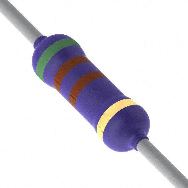
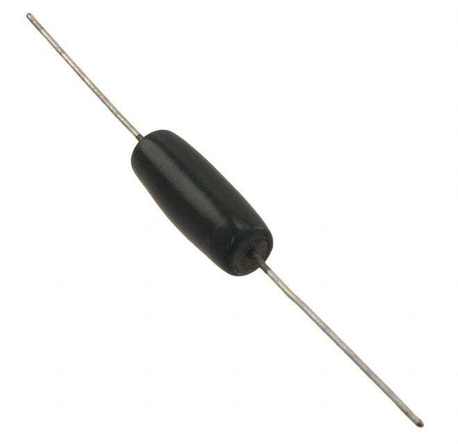
ICGOO电子元器件商城为您提供RS02B1R500FE70由Vishay设计生产,在icgoo商城现货销售,并且可以通过原厂、代理商等渠道进行代购。 RS02B1R500FE70价格参考。VishayRS02B1R500FE70封装/规格:通孔电阻器, 1.5 Ohms ±1% 3W 轴向 通孔电阻器 防潮 绕线。您可以下载RS02B1R500FE70参考资料、Datasheet数据手册功能说明书,资料中有RS02B1R500FE70 详细功能的应用电路图电压和使用方法及教程。
Vishay Dale的RS02B1R500FE70是一款通孔电阻器,属于RS02系列,具有1.5Ω的阻值,精度为±1%,额定功率为0.6W,采用耐高温、高稳定性的金属膜结构,适用于对精度和稳定性要求较高的电子电路。

该电阻器广泛应用于以下场景:

1. 工业控制设备:如PLC(可编程控制器)、变频器和伺服驱动器中,用于信号采样、电流检测和电压分压等关键电路。

2. 电源管理系统:用于开关电源、DC-DC转换器和稳压模块中,作为反馈电阻或限流电阻,确保系统稳定运行。

3. 测量仪器:如万用表、示波器和电能质量分析仪中,用于高精度信号处理和测量电路。

4. 通信设备:在基站、路由器和交换机等设备中,用于偏置电路和信号调节电路,保障通信信号的稳定性和准确性。

5. 汽车电子系统:如车载充电系统、电池管理系统(BMS)和传感器模块中,用于电流采样和信号调理。

该电阻器因其良好的温度稳定性和长期可靠性,适合在要求高性能和高稳定性的场合使用。
| 参数 | 数值 |
| 产品目录 | |
| 描述 | RES 1.5 OHM 3W 1% WW AXIAL线绕电阻器 - 透孔 3watts 1.5ohms 1% |
| 产品分类 | |
| 品牌 | Vishay DaleVishay / Dale |
| 产品手册 | |
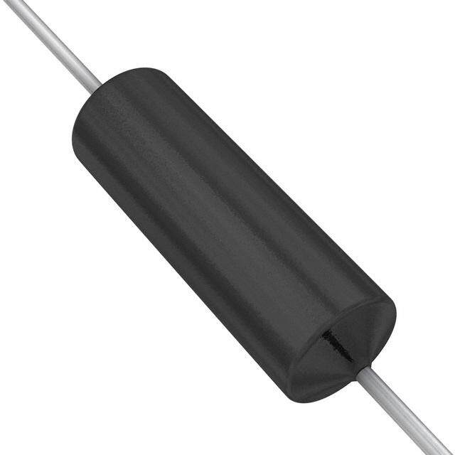
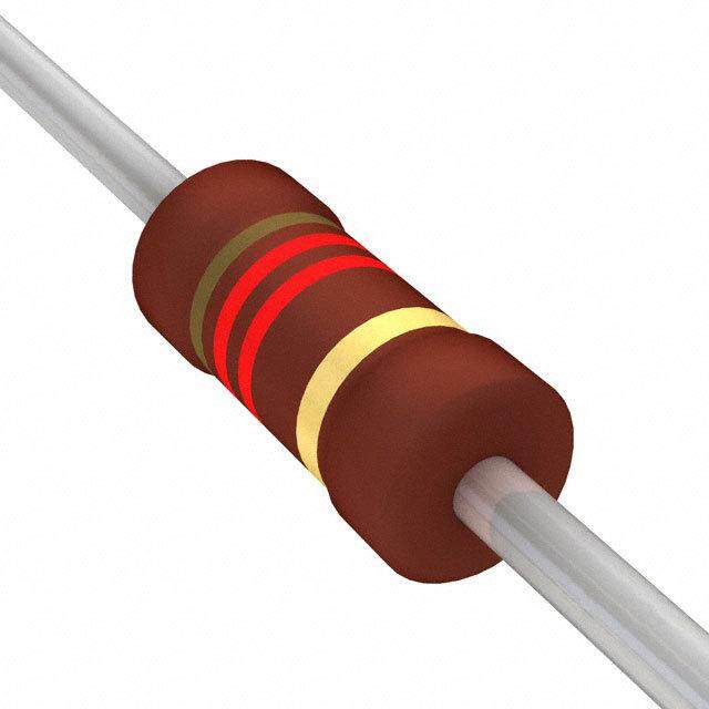
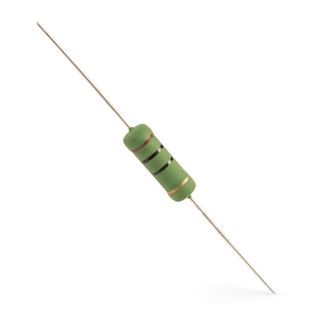
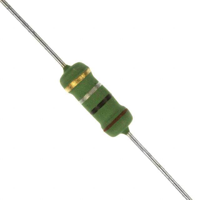
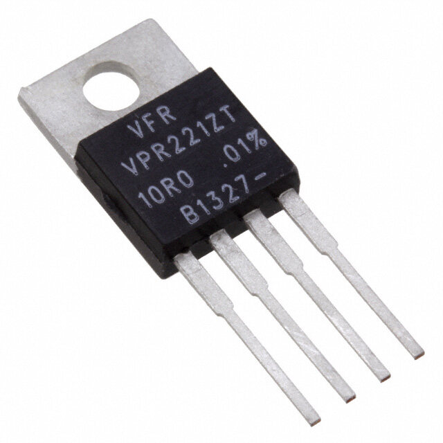
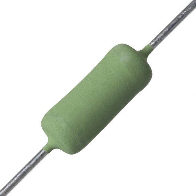
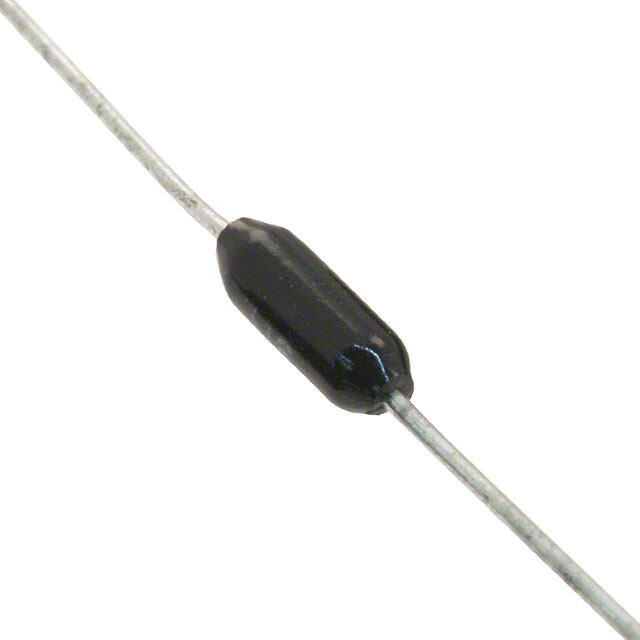
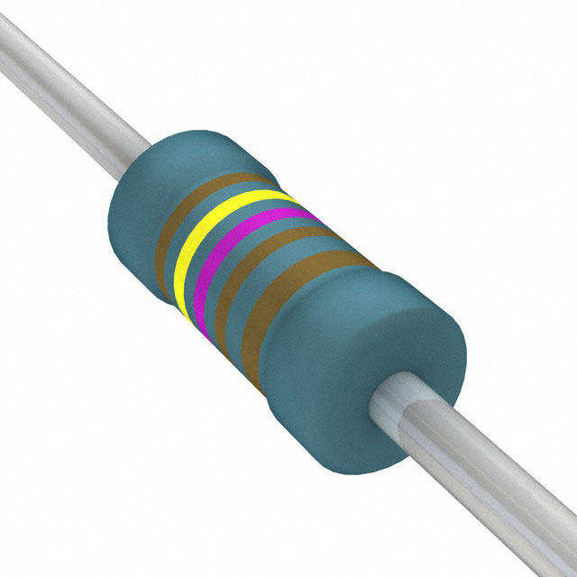
| 产品图片 |
|
| rohs | 符合RoHS无铅 / 符合限制有害物质指令(RoHS)规范要求 |
| 产品系列 | 线绕电阻器,线绕电阻器 - 透孔,Vishay / Dale RS02B1R500FE70RS |
| 数据手册 | |
| 产品型号 | RS02B1R500FE70RS02B1R500FE70 |
| 产品 | Power Resistors Wirewound Silicone Coated |
| 产品目录绘图 |
|
| 产品目录页面 | |
| 产品种类 | 线绕电阻器 - 透孔 |
| 供应商器件封装 | 轴向 |
| 其它名称 | RSB-1.5RCT |
| 功率(W) | 3W |
| 功率额定值 | 3 W |
| 包装 | 剪切带 (CT) |
| 商标 | Vishay / Dale |
| 外壳直径 | 4.75 mm |
| 外壳长度 | 14.22 mm |
| 大小/尺寸 | 0.187" 直径 x 0.560" 长(4.75mm x 14.22mm) |
| 容差 | 1 %±1% |
| 封装/外壳 | 轴向 |
| 工作温度范围 | - 65 C to + 250 C |
| 工厂包装数量 | 1000 |
| 引线直径 | 0.81 mm |
| 成分 | 绕线 |
| 标准包装 | 1 |
| 温度系数 | 50 PPM / C±50ppm/°C |
| 特性 | 防潮 |
| 电阻 | 1.5 Ohms |
| 电阻(Ω) | 1.5 |
| 端子数 | 2 |
| 端接类型 | Axial |
| 类型 | Wirewound Resistors, Industrial, Precision Power, Silicon Coated, Axial Lead |
| 系列 | RS |
| 高度 | - |


PDF Datasheet 数据手册内容提取
RS, NS www.vishay.com Vishay Dale Wirewound Resistors, Industrial, Precision Power, Silicone Coated, Axial Lead FEATURES • High temperature coating (> 350 °C) • Complete welded construction • Meets applicable requirements of MIL-PRF-26 Available • Available in non-inductive styles (type NS) with Ayrton-Perry winding for lowest reactive components • Excellent stability in operation (typical resistance shift < 0.5 %) DESIGN SUPPORT TOOLS click logo to get started • MIL-PRF-26 qualified, type RW resistors can Available be found at: www.vishay.com/doc?30281 • Material categorization: Available for definitions of compliance please see Models www.vishay.com/doc?99912 Available Available Note * This datasheet provides information about parts that are RoHS-compliant and / or parts that are non RoHS-compliant. For example, parts with lead (Pb) terminations are not RoHS-compliant. Please see the information / tables in this datasheet for details STANDARD ELECTRICAL SPECIFICATIONS POWER POWER RESISTANCE RESISTANCE RESISTANCE RESISTANCE RESISTANCE RATING (1) RATING (1) RANGE RANGE RANGE RANGE RANGE WEIGHT GLOBAL HIST. P W P W (typical) MODEL MODEL 25 °C 25 °C U ± 0.05 % V ± 3 % ± 0.5 %, ± 3 %, ± 5 %, g to ± 5 % to ± 10 % ± 0.05 % ± 0.1 % ± 0.25 % ± 1 % ± 10 % RS1/4 RS-1/4 0.4 - 1 to 1K 0.499 to 1K 0.499 to 3.4K 0.1 to 3.4K 0.1 to 3.4K 0.21 RS1/2 RS-1/2 0.75 - 1 to 1.3K 0.499 to 1.3K 0.499 to 4.9K 0.1 to 4.9K 0.1 to 4.9K 0.23 RS01A RS-1A 1.0 - 1 to 2.74K 0.499 to 2.74K 0.499 to 10.4K 0.1 to 10.4K 0.1 to 10.4K 0.34 RS01A...300 RS-1A-300 1.0 - - 0.499 to 2.74K 0.499 to 10.4K 0.1 to 10.4K - 0.34 RS01M RS-1M 1.0 - 1 to 1.32K 0.499 to 1.67K 0.499 to 6.85K 0.1 to 6.85K 0.1 to 6.85K 0.30 RS002 RS-2 4.0 5.5 0.499 to 12.7K 0.499 to 12.7K 0.1 to 47.1K 0.1 to 47.1K 0.1 to 47.1K 2.10 RS02M RS-2M 3.0 - 0.499 to 4.49K 0.499 to 4.49K 0.1 to 18.74K 0.1 to 18.74K 0.1 to 18.74K 0.65 RS02B RS-2B 3.0 3.75 0.499 to 6.5K 0.499 to 6.5K 0.1 to 24.5K 0.1 to 24.5K 0.1 to 24.5K 0.70 RS02B...300 RS-2B-300 3.0 - - 0.499 to 6.5K 0.1 to 24.5K 0.1 to 24.5K - 0.70 RS02C RS-2C 2.5 3.25 0.499 to 8.6K 0.499 to 8.6K 0.1 to 32.3K 0.1 to 32.3K 0.1 to 32.3K 1.6 RS02C...17 RS-2C-17 2.5 3.25 0.499 to 8.6K 0.499 to 8.6K 0.1 to 32.3K 0.1 to 32.3K 0.1 to 32.3K 1.6 RS02C...23 RS-2C-23 - 3.25 - - - - 0.1 to 32.3K 1.6 RS005 RS-5 5.0 6.5 0.499 to 25.7K 0.499 to 25.7K 0.1 to 95.2K 0.1 to 95.2K 0.1 to 95.2K 4.2 RS005...69 RS-5-69 5.0 - - 0.499 to 25.7K 0.1 to 95.2K 0.1 to 95.2K 0.1 to 95.2K 4.2 RS005...70 RS-5-70 - 6.5 - - - - 0.1 to 95.2K 4.2 RS007 RS-7 7.0 9.0 0.499 to 41.4K 0.499 to 41.4K 0.1 to 154K 0.1 to 154K 0.1 to 154K 4.7 RS010 RS-10 10.0 13.0 0.499 to 73.4K 0.499 to 73.4K 0.1 to 273K 0.1 to 273K 0.1 to 273K 9.0 RS010...38 RS-10-38 10.0 - - 0.499 to 73.4K 0.1 to 273K 0.1 to 273K 0.1 to 273K 9.0 RS010...39 RS-10-39 - 13.0 - - - - 0.1 to 273K 9.0 Notes • Models not available as lead (Pb)-free: RS01A...300, RS02B...300, RS02C...23, RS005...69, RS005...70, RS010...38, RS010...39. • Shaded area indicates most popular models. (1) Vishay Dale RS models have two power ratings depending on operation temperature and stability requirements. Models not available for characteristic V are: RS1/4, RS1/2, RS01A, RS01A…300, RS01M, RS02M, RS02B…300, RS005…69, and RS010…38. GLOBAL PART NUMBER INFORMATION Global Part Numbering example: RS02C10K00FS7017 R S 0 2 C 1 0 K 0 0 F S 7 0 1 7 GLOBAL MODEL RESISTANCE VALUE TOLERANCE CODE PACKAGING SPECIAL (5 digits) (5 digits) (1 digit) (3 digits) (up to 3 digits) (see Standard R = decimal A = 0.05 % E70 = lead (Pb)-free, tape / reel (smaller than RS005) (dash number) Electrical K = thousand B = 0.1 % E73 = lead (Pb)-free, tape / reel (RS005 and larger) from 1 to 999 Specifications 15R00 = 15 C = 0.25 % E12 = lead (Pb)-free, bulk as applicable Global Model 10K00 = 10 k D = 0.5 % column for options) F = 1.0 % S70 = tin / lead, tape / reel (smaller than RS005) H = 3.0 % S73 = tin / lead, tape / reel (RS005 and larger) J = 5.0 % B12 = tin / lead, bulk K = 10.0 % Historical Part Numbering example: RS-2C-17 10 k 1 % S70 RS-2C-17 10 k 1 % S70 HISTORICAL MODEL RESISTANCE VALUE TOLERANCE CODE PACKAGING Revision: 15-Nov-17 1 Document Number: 30204 For technical questions, contact: ww2aresistors@vishay.com THIS DOCUMENT IS SUBJECT TO CHANGE WITHOUT NOTICE. THE PRODUCTS DESCRIBED HEREIN AND THIS DOCUMENT ARE SUBJECT TO SPECIFIC DISCLAIMERS, SET FORTH AT www.vishay.com/doc?91000
RS, NS www.vishay.com Vishay Dale DIMENSIONS in inches [millimeters] DIMENSIONS in inches [millimeters] A 1.50 GLOBAL B (1) [38.10] (1) MODEL A C D (max.) min. 0.250 ± 0.031 0.281 0.085 ± 0.020 0.020 ± 0.002 RS1/4 [6.35 ± 0.787] [7.14] [2.16 ± 0.508] [0.508 ± 0.051] D B 0.312 ± 0.016 0.328 0.078 + 0.016 - 0.031 0.020 ± 0.002 C RS1/2 [7.92 ± 0.406] [8.33] [1.98 + 0.406 - 0.787] [0.508 ± 0.051] Note (1) On some standard reel pack methods, the leads may be RS01A 0.406 ± 0.031 0.437 0.094 ± 0.031 0.020 ± 0.002 trimmed to a shorter length than shown RS01A...300 [10.31 ± 0.787] [11.10] [2.39 ± 0.787] [0.508 ± 0.051] 0.270 ± 0.031 0.311 0.110 ± 0.015 0.020 ± 0.002 RS01M MATERIAL SPECIFICATIONS [6.86 ± 0.787] [7.90] [2.79 ± 0.381] [0.508 ± 0.051] Element: copper-nickel alloy or nickel-chrome alloy, 0.625 ± 0.062 0.765 0.250 ± 0.031 0.040 ± 0.002 RS002 depending on resistance value [15.88 ± 1.57] [19.43] [6.35 ± 0.787] [1.02 ± 0.051] 0.500 ± 0.062 0.562 0.185 ± 0.031 0.032 ± 0.002 Core: ceramic, steatite or alumina, depending on physical RS02M [12.70 ± 1.57] [14.27] [4.70 ± 0.787] [0.813 ± 0.051] size RS02B 0.560 ± 0.062 0.622 0.187 ± 0.031 0.032 ± 0.002 Coating: special high temperature silicone RS02B...300 [14.22 ± 1.57] [15.80] [4.75 ± 0.787] [0.813 ± 0.051] 0.500 ± 0.062 0.593 0.218 ± 0.031 0.040 ± 0.002 Standard Terminals: 100 % Sn, or 60/40 Sn/Pb coated RS02C [12.70 ± 1.57] [15.06] [5.54 ± 0.787] [1.02 ± 0.051] Copperweld® RS02C...17 0.500 ± 0.062 0.593 0.218 ± 0.031 0.032 ± 0.002 End Caps: stainless steel RS02C...23 [12.70 ± 1.57] [15.06] [5.54 ± 0.787] [0.813 ± 0.051] Part Marking: DALE, model, wattage (1), value, tolerance, RS005 0.875 ± 0.062 1.0 0.312 ± 0.031 0.040 ± 0.002 RS005...69 date code RS005...70 [22.23 ± 1.57] [25.4] [7.92 ± 0.787] [1.02 ± 0.051] Note 1.22 ± 0.062 1.28 0.312 ± 0.031 0.040 ± 0.002 (1) Wattage marked on part will be “U” characteristic RS007 [30.99 ± 1.57] [32.51] [7.92 ± 0.787] [1.02 ± 0.051] RS010 1.78 ± 0.062 1.87 0.375 ± 0.031 0.040 ± 0.002 DERATING RS010...39 [45.21 ± 1.57] [47.50] [9.53 ± 0.787] [1.02 ± 0.051] % 120 1.78 ± 0.062 1.84 0.375 ± 0.031 0.040 ± 0.002 N I R E W O 100 N(1)oRtBSe0 (1m0.a..3x8.) dime[4n5s.2io1 n± 1is.5 c7]lean [4le6a.7d4 ]to cl[9e.a5n3 ±le 0a.7d87] [1.02 ± 0.051] P D E T A R 8600 NMSod NelsO oNf- eINquDivUalCenTt IpVhEysical and electrical specifications CHAR. V are available with non-inductive (Ayrton-Perry) winding. 40 They are identified by substituting the letter N for R in the model number (NS005, for example). 20 Two conditions apply: CHAR. U 1. For NS models, divide maximum resistance values by two 0 2. Body O.D. on NS02C may exceed that of the RS02C by - 65 - 50 0 50 150 250 350 25 AMBIENT TEMPERATURE IN °C 0.010" TECHNICAL SPECIFICATIONS PARAMETER UNIT RS RESISTOR CHARACTERISTICS Temperature Coefficient ppm/°C ± 20 for 10 and above, ± 50 for 1 to 9.9 , ± 90 for 0.5 to 0.99 Maximum Working Voltage V (P x R)1/2 Insulation Resistance 1000 M minimum dry, 100 M minimum after moisture test Operating Temperature Range °C Characterisitic U = -65 to +250, characteristic V = -65 to +350 PERFORMANCE TEST LIMITS TEST CONDITIONS OF TEST CHARACTERISTIC U CHARACTERISTIC V Thermal Shock Rated power applied until thermally stable, then a minimum of 15 min at -55 °C ± (0.2 % + 0.05 ) R ± (2.0 % + 0.05 ) R Short Time Overload 5x rated power (3.75 W and smaller), 10 x rated power (4 W and larger) for 5 s ± (0.2 % + 0.05 ) R ± (2.0 % + 0.05 ) R Dielectric Withstanding Voltage 500 VRMS min. for RS1/4 thru RS01A, 1000 VRMS for all others, duration of 1 min ± (0.1 % + 0.05 ) R ± (0.1 % + 0.05 ) R Low Temperature Storage -65 °C for 24 h ± (0.2 % + 0.05 ) R ± (2.0 % + 0.05 ) R High Temperature Exposure 250 h at: U = +250 °C, V = +350 °C ± (0.5 % + 0.05 ) R ± (2.0 % + 0.05 ) R Moisture Resistance MIL-STD-202 Method 106, 7b not applicable ± (0.2 % + 0.05 ) R ± (2.0 % + 0.05 ) R Shock, Specified Pulse MIL-STD-202 Method 213, 100 g’s for 6 ms, 10 shocks ± (0.1 % + 0.05 ) R ± (0.2 % + 0.05 ) R Vibration, High Frequency Frequency varied 10 Hz to 2000 Hz, 20 g peak, 2 directions 6 h each ± (0.1 % + 0.05 ) R ± (0.2 % + 0.05 ) R Load Life 2000 h at rated power, +25 °C, 1.5 h “ON”, 0.5 h “OFF” ± (0.5 % + 0.05 ) R ± (3.0 % + 0.05 ) R Pull test 5 s to 10 s, 5 lb (RS1/4 thru RS01A), 10 lb for all others; Terminal Strength ± (0.1 % + 0.05 ) R ± (1.0 % + 0.05 ) R torsion test - 3 alternating directions, 360° each Revision: 15-Nov-17 2 Document Number: 30204 For technical questions, contact: ww2aresistors@vishay.com THIS DOCUMENT IS SUBJECT TO CHANGE WITHOUT NOTICE. THE PRODUCTS DESCRIBED HEREIN AND THIS DOCUMENT ARE SUBJECT TO SPECIFIC DISCLAIMERS, SET FORTH AT www.vishay.com/doc?91000
Legal Disclaimer Notice www.vishay.com Vishay Disclaimer ALL PRODUCT, PRODUCT SPECIFICATIONS AND DATA ARE SUBJECT TO CHANGE WITHOUT NOTICE TO IMPROVE RELIABILITY, FUNCTION OR DESIGN OR OTHERWISE. Vishay Intertechnology, Inc., its affiliates, agents, and employees, and all persons acting on its or their behalf (collectively, “Vishay”), disclaim any and all liability for any errors, inaccuracies or incompleteness contained in any datasheet or in any other disclosure relating to any product. Vishay makes no warranty, representation or guarantee regarding the suitability of the products for any particular purpose or the continuing production of any product. To the maximum extent permitted by applicable law, Vishay disclaims (i) any and all liability arising out of the application or use of any product, (ii) any and all liability, including without limitation special, consequential or incidental damages, and (iii) any and all implied warranties, including warranties of fitness for particular purpose, non-infringement and merchantability. Statements regarding the suitability of products for certain types of applications are based on Vishay’s knowledge of typical requirements that are often placed on Vishay products in generic applications. Such statements are not binding statements about the suitability of products for a particular application. It is the customer’s responsibility to validate that a particular product with the properties described in the product specification is suitable for use in a particular application. Parameters provided in datasheets and / or specifications may vary in different applications and performance may vary over time. All operating parameters, including typical parameters, must be validated for each customer application by the customer’s technical experts. Product specifications do not expand or otherwise modify Vishay’s terms and conditions of purchase, including but not limited to the warranty expressed therein. Except as expressly indicated in writing, Vishay products are not designed for use in medical, life-saving, or life-sustaining applications or for any other application in which the failure of the Vishay product could result in personal injury or death. Customers using or selling Vishay products not expressly indicated for use in such applications do so at their own risk. Please contact authorized Vishay personnel to obtain written terms and conditions regarding products designed for such applications. No license, express or implied, by estoppel or otherwise, to any intellectual property rights is granted by this document or by any conduct of Vishay. Product names and markings noted herein may be trademarks of their respective owners. © 2017 VISHAY INTERTECHNOLOGY, INC. ALL RIGHTS RESERVED Revision: 08-Feb-17 1 Document Number: 91000