ICGOO在线商城 > 电阻器 > 芯片电阻 - 表面安装 > RMCF2512JT2R70

 Datasheet下载
- 型号: RMCF2512JT2R70
- 制造商: STACKPOLE ELECTRONICS INC.
- 库位|库存: xxxx|xxxx
- 要求:
| 数量阶梯 | 香港交货 | 国内含税 |
| +xxxx | $xxxx | ¥xxxx |
查看当月历史价格
查看今年历史价格
RMCF2512JT2R70产品简介:
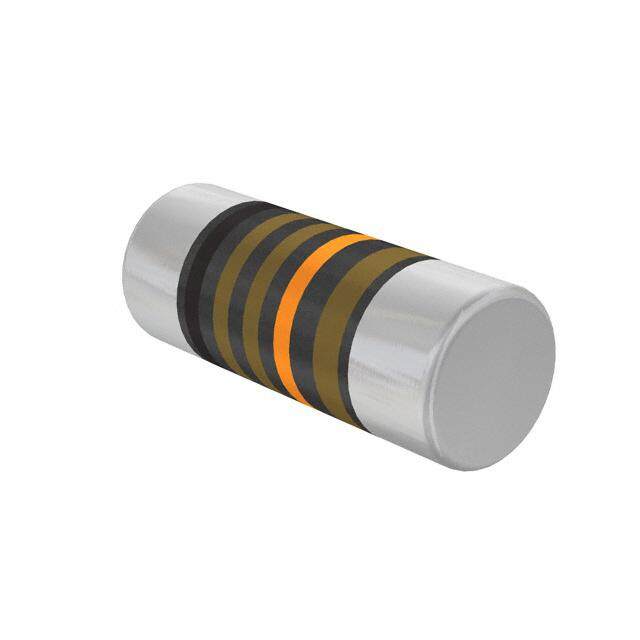
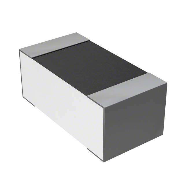
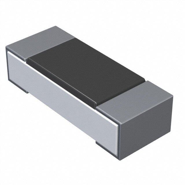
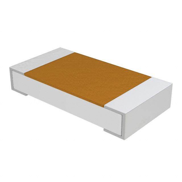
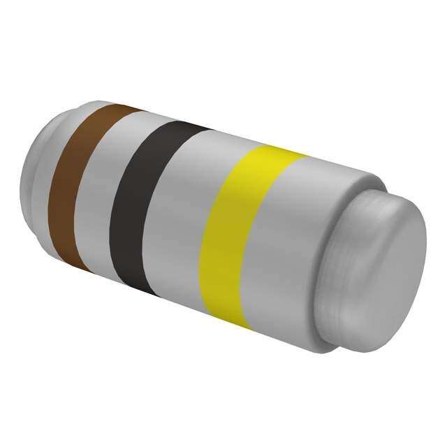
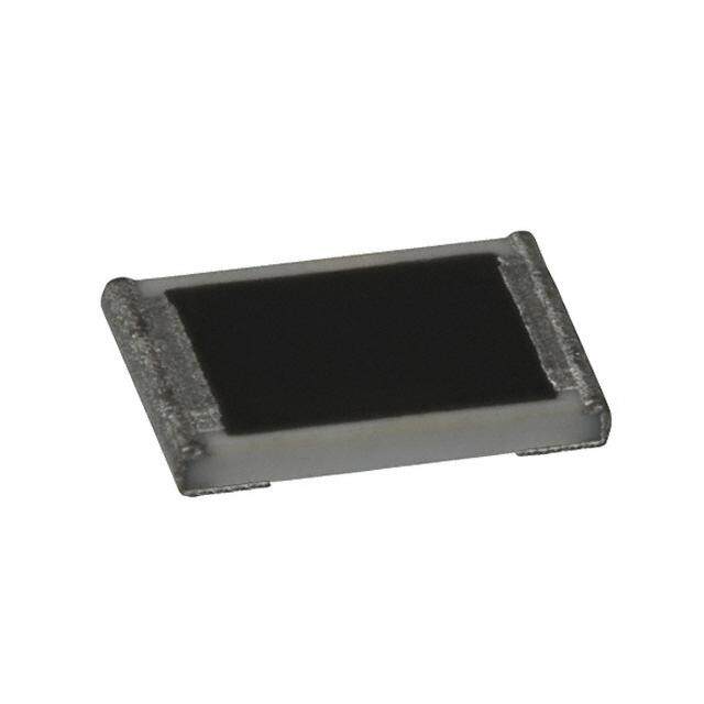
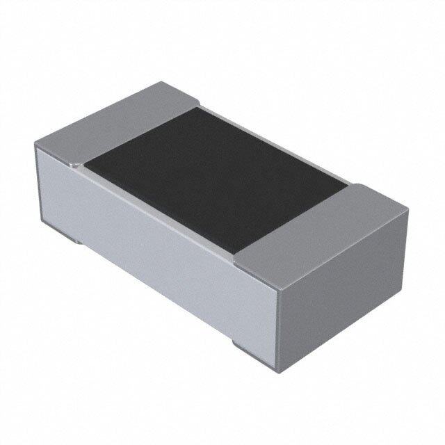
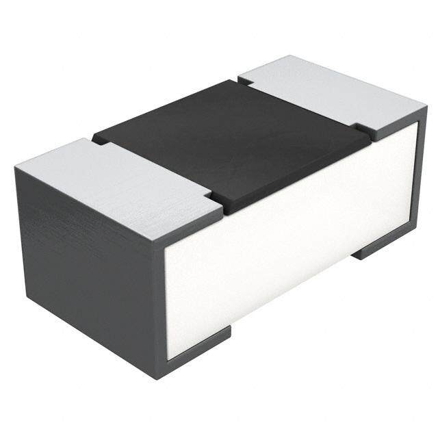
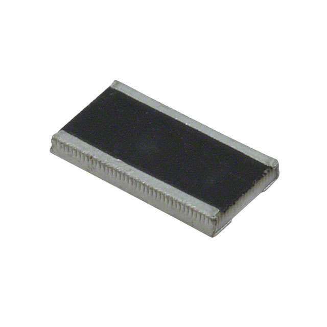
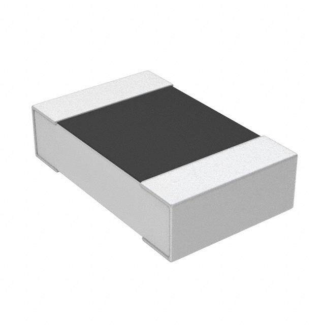
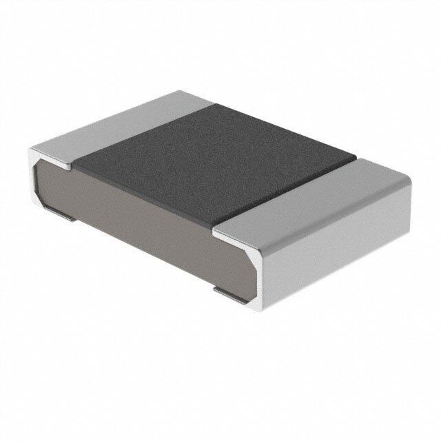
ICGOO电子元器件商城为您提供RMCF2512JT2R70由STACKPOLE ELECTRONICS INC.设计生产,在icgoo商城现货销售,并且可以通过原厂、代理商等渠道进行代购。 RMCF2512JT2R70价格参考。STACKPOLE ELECTRONICS INC.RMCF2512JT2R70封装/规格:芯片电阻 - 表面安装, 2.7 Ohms ±5% 1W 厚膜 芯片电阻 2512(6432 公制) 汽车级 AEC-Q200 厚膜。您可以下载RMCF2512JT2R70参考资料、Datasheet数据手册功能说明书,资料中有RMCF2512JT2R70 详细功能的应用电路图电压和使用方法及教程。
Stackpole Electronics Inc.生产的RMCF2512JT2R70是一款芯片电阻,属于表面安装器件(SMD)。其应用场景广泛,主要应用于需要高精度、高稳定性和高功率处理能力的电子电路中。以下是该型号的主要应用场景:

 1. 电源管理
   - 用于开关电源(SMPS)、DC-DC转换器和电压调节模块中的电流检测和负载均衡。
   - 在电源电路中作为分流电阻,帮助监测电流大小。

 2. 信号调理
   - 在放大器、滤波器和传感器接口电路中用作精密电阻,确保信号的准确性和稳定性。
   - 用于音频设备中的信号衰减和匹配阻抗。

 3. 通信设备
   - 应用于无线通信模块、路由器和基站中,作为匹配网络的一部分,优化信号传输效率。
   - 在射频(RF)电路中提供稳定的阻抗匹配和滤波功能。

 4. 工业控制
   - 在工业自动化设备中用于电机驱动器、变频器和控制系统中的电流检测和保护电路。
   - 用于温度传感器、压力传感器等数据采集系统的信号调理电路。

 5. 消费电子产品
   - 在智能手机、平板电脑和其他便携式设备中,用于电池管理、充电电路和信号处理。
   - 在LED驱动电路中作为限流电阻,确保LED正常工作。

 6. 汽车电子
   - 应用于车载电子系统,如发动机控制单元(ECU)、防抱死制动系统(ABS)和车载信息娱乐系统。
   - 在新能源汽车中用于电池管理系统(BMS)中的电流检测。

 7. 医疗设备
   - 在监护仪、超声设备和其他医疗仪器中用于信号放大和滤波。
   - 提供高精度和低噪声特性,确保测量结果的准确性。

 特性优势:
- 高功率密度:RMCF系列具有较高的功率处理能力,适合大电流应用。
- 低温度系数:保证在宽温范围内阻值稳定。
- 耐硫化设计:适合恶劣环境下的长期使用。
- 小型化设计:2512封装节省空间,便于高密度电路板设计。

综上所述,RMCF2512JT2R70适用于需要高可靠性、高精度和高功率处理能力的各种电子设备和系统中。
| 参数 | 数值 |
| 产品目录 | |
| 描述 | RES 2.7 OHM 1W 5% 2512 |
| 产品分类 | |
| 品牌 | Stackpole Electronics Inc |
| 数据手册 | |
| 产品图片 |
|
| 产品型号 | RMCF2512JT2R70 |
| PCN零件编号 | |
| rohs | 无铅 / 符合限制有害物质指令(RoHS)规范要求 |
| 产品系列 | RMCF |
| 产品目录绘图 |
|
| 供应商器件封装 | 2512 |
| 其它名称 | RMCF2512JT2R70CT |
| 功率(W) | 1W |
| 包装 | 剪切带 (CT) |
| 大小/尺寸 | 0.248" 长 x 0.126" 宽(6.30mm x 3.20mm) |
| 容差 | ±5% |
| 封装/外壳 | 2512(6432 公制) |
| 成分 | 厚膜 |
| 标准包装 | 1 |
| 温度系数 | ±400ppm/°C |
| 特性 | - |
| 电阻(Ω) | 2.7 |
| 端子数 | 2 |
| 高度 | 0.028"(0.70mm) |
.jpg)


- 商务部:美国ITC正式对集成电路等产品启动337调查
- 曝三星4nm工艺存在良率问题 高通将骁龙8 Gen1或转产台积电
- 太阳诱电将投资9.5亿元在常州建新厂生产MLCC 预计2023年完工
- 英特尔发布欧洲新工厂建设计划 深化IDM 2.0 战略
- 台积电先进制程称霸业界 有大客户加持明年业绩稳了
- 达到5530亿美元!SIA预计今年全球半导体销售额将创下新高
- 英特尔拟将自动驾驶子公司Mobileye上市 估值或超500亿美元
- 三星加码芯片和SET,合并消费电子和移动部门,撤换高东真等 CEO
- 三星电子宣布重大人事变动 还合并消费电子和移动部门
- 海关总署:前11个月进口集成电路产品价值2.52万亿元 增长14.8%


PDF Datasheet 数据手册内容提取
Stackpole Electronics, Inc. Packaging and Technical Information Resistive Product Solutions Radial Lead Taping Specification – Pana-Sert Carbon Film & Metal Film Resistors (1/4 W Body Size) Symbol Description PANA-SERT Unit Symbol Description PANA-SERT Unit 0.256 ± 0.020 inches 0.433 max. inches A Resistor body length L Cutout Length (1) 6.50 ± 0.50 mm 11.00 max. mm 0.098 ± 0.020 inches 0.500 ± 0.039 inches C Height of bending P Resistor pitch (1) 2.50 ± 0.50 mm 12.70 ± 1.00 mm D Resistor body diameter 0.091 ± 0.008 inches P Sprocket-hole pitch (1) 0.500 ± 0.012 inches 2.30 ± 0.20 mm 0 12.70 ± 0.30 mm 0.157 ± 0.012 inches Sprocket-hole center to 0 . 1 52 ± 0.028 inches D Sprocket-hole diameter P 0 4.00 ± 0.30 mm 1 lead center 3.85 ± 0.70 mm 0.197 ± 0.039 inches Sprocket-hole center to 0 .250 ± 0.051 inches F Resistor lead spacing P 5.00 ± 1.00 mm 2 resistor center (1) 6.35 ± 1.30 mm 0.748 ± 0.039 inches Thickness 0 . 0 2 8 ± 0 . 0 08 inches H Height to bottom of resistor T 19.00 ± 1.00 mm (chipboard and tape) 0.70 ± 0.20 mm 0.630 ± 0.020 inches 0.709 ± 0.039 inches H Height to lead clinch W Chipboard width (1) 0 16.00 ± 0.50 mm 18.00 ± 1.00 mm 1.122 max. inches 0.49 min. inches H Height of resistor W Hold-down tape width 1 28.50 max. mm 0 12.50 min. mm 0 ± 0.079 (0 ± 5º) inches 0.354 ± 0.030 inches h Resistor alignment W Sprocket-hole position 0 ± 2.00 (0 ± 5º) mm 1 9.00 ± 0.75 mm 0 ± 0.079 (0 ± 5º) inches 0.118 max. inches h Resistor alignment W Hold-down tape position 1 0 ± 2.00 (0 ± 5º) mm 2 3.00 max. mm 0.079 max. inches I Lead protrusion 2.00 max. mm Rev Date: 01/02/2020 1 www.seielect.com This specification may be changed at any time without prior notice marketing@seielect.com Please confirm technical specifications before you order and/or use.
Stackpole Electronics, Inc. Packaging and Technical Information Resistive Product Solutions Axial Leaded Resistor Packaging & Identification Variations Lead-Tape Specifications: Reeled in accordance with EIA-296-F Series Code A max.(1) B max C D(2) Tape Unit 3.917 13.504 0.394 ± 0.020 2.063 ± 0.079 0.250 inches ASR 1 99.50 343.00 10.00 ± 0.50 52.40 ± 2.00 6.350 mm 2.508 13.504 0.197 ± 0.020 2.063 ± 0.079 0.250 inches 14 63.70 343.00 5.00 ± 0.50 52.40 ± 2.00 6.350 mm ASRM 2.618 13.504 0.197 ± 0.020 2.063 ± 0.079 0.250 inches 12 66.50 343.00 5.00 ± 0.50 52.40 ± 2.00 6.350 mm 2.508 13.504 0.197 ± 0.020 2.063 ± 0.079 0.250 inches 18 63.70 343.00 5.00 ± 0.50 52.40 ± 2.00 6.350 mm 2.618 13.504 0.197 ± 0.020 2.063 ± 0.079 0.250 inches CD 14 66.50 343.00 5.00 ± 0.50 52.40 ± 2.00 6.350 mm 12 2.736 13.504 0.197 ± 0.020 2.063 ± 0.079 0.250 inches 69.50 343.00 5.00 ± 0.50 52.40 ± 2.00 6.350 mm 2.508 13.504 0.197 ± 0.020 2.063 ± 0.079 0.250 inches 18 63.70 343.00 5.00 ± 0.50 52.40 ± 2.00 6.350 mm 2.638 13.504 0.197 ± 0.020 2.063 ± 0.079 0.250 inches 14 67.00 343.00 5.00 ± 0.50 52.40 ± 2.00 6.350 mm 2.736 13.504 0.197 ± 0.020 2.063 ± 0.079 0.250 inches CF 12 69.50 343.00 5.00 ± 0.50 52.40 ± 2.00 6.350 mm 1 2.972 13.504 0.197 ± 0.020 2.063 ± 0.079 0.250 inches 75.50 343.00 5.00 ± 0.50 52.40 ± 2.00 6.350 mm 3.130 13.504 0.394 ± 0.020 2.063 ± 0.079 0.250 inches 2 79.50 343.00 10.00 ± 0.50 52.40 ± 2.00 6.350 mm 2.508 13.504 0.197 ± 0.020 2.063 ± 0.079 0.250 inches 14 63.70 343.00 5.00 ± 0.50 52.40 ± 2.00 6.350 mm CFM 2.638 13.504 0.197 ± 0.020 2.063 ± 0.079 0.250 inches 12 67.00 343.00 5.00 ± 0.50 52.40 ± 2.00 6.350 mm 14 2.618 13.504 0.197 ± 0.020 2.063 ± 0.079 0.250 inches 66.50 343.00 5.00 ± 0.50 52.40 ± 2.00 6.350 mm 2.736 13.504 0.197 ± 0.020 2.063 ± 0.079 0.250 inches 12 69.50 343.00 5.00 ± 0.50 52.40 ± 2.00 6.350 mm FRN 2.421 13.504 0.197 ± 0.020 2.063 ± 0.079 0.250 inches 1 61.50 343.00 5.00 ± 0.50 52.40 ± 2.00 6.350 mm 3.917 13.504 0.394 ± 0.020 2.500 ± 0.079 0.250 inches 2 99.50 343.00 10.00 ± 0.50 63.50 ± 2.00 6.350 mm 1 3.311 13.504 0.197 ± 0.020 2.063 ± 0.079 0.250 inches 84.10 343.00 5.00 ± 0.50 52.40 ± 2.00 6.350 mm 3.484 13.504 0.394 ± 0.020 2.063 ± 0.079 0.250 inches 3 88.50 343.00 10.00 ± 0.50 52.40 ± 2.00 6.350 mm MR 3.850 13.504 0.394 ± 0.020 2.875 ± 0.079 0.250 inches 5 97.80 343.00 10.00 ± 0.50 73.03 ± 2.00 6.350 mm 4.764 13.504 0.394 ± 0.020 4.310 ± 0.079 0.250 inches 10 121.00 343.00 10.00 ± 0.50 109.47 ± 2.00 6.350 mm Rev Date: 01/02/2020 2 www.seielect.com This specification may be changed at any time without prior notice marketing@seielect.com Please confirm technical specifications before you order and/or use.
Stackpole Electronics, Inc. Packaging and Technical Information Resistive Product Solutions Lead Tape Specifications: Reeled in accordance with EIA-296-F (cont.) Series Code A max.(1) B max C D(2) Tape Unit 3.563 13.504 0.394 ± 0.020 2.063 ± 0.079 0.250 inches 1 90.50 343.00 10.00 ± 0.50 52.40 ± 2.00 6.350 mm 3.736 13.504 0.394 ± 0.020 2.063 ± 0.079 0.250 inches 3 94.90 343.00 10.00 ± 0.50 52.40 ± 2.00 6.350 mm MWW 4.094 13.504 0.394 ± 0.020 2.063 ± 0.079 0.250 inches 5 104.00 343.00 10.00 ± 0.50 52.40 ± 2.00 6.350 mm 10 5.118 13.504 0.394 ± 0.020 2.063 ± 0.079 0.250 inches 130.00 343.00 10.00 ± 0.50 52.40 ± 2.00 6.350 mm 2.787 13.504 0.394 ± 0.020 2.063 ± 0.079 0.250 inches 14 70.80 343.00 10.00 ± 0.50 52.40 ± 2.00 6.350 mm RC 2.756 13.504 0.394 ± 0.020 2.063 ± 0.079 0.250 inches 12 70.00 343.00 10.00 ± 0.50 52.40 ± 2.00 6.350 mm 2.756 ± 0.118 11.811 ± 0.197 0.197 ± 0.020 2.047 ± 0.020 0.250 inches 18 70.00 ± 3.00 300.00 ± 5.00 5.00 ± 0.50 52.00 ± 0.50 6.350 mm 14 2.756 ± 0.118 11.811 ± 0.197 0.197 ± 0.020 2.047 ± 0.020 0.250 inches 70.00 ± 3.00 300.00 ± 5.00 5.00 ± 0.50 52.00 ± 0.50 6.350 mm 2.756 ± 0.118 11.811 ± 0.197 0.197 ± 0.020 2.047 ± 0.020 0.250 inches RNF 12 70.00 ± 3.00 300.00 ± 5.00 5.00 ± 0.50 52.00 ± 0.50 6.350 mm 2.756 ± 0.118 11.811 ± 0.197 0.197 ± 0.020 2.047 ± 0.020 0.250 inches 1 70.00 ± 3.00 300.00 ± 5.00 5.00 ± 0.50 52.00 ± 0.50 6.350 mm 2.756 ± 0.118 11.811 ± 0.197 0.197 ± 0.020 2.047 ± 0.020 0.250 inches 2 70.00 ± 3.00 300.00 ± 5.00 5.00 ± 0.50 52.00 ± 0.50 6.350 mm 14 2.756 ± 0.118 11.811 ± 0.197 0.197 ± 0.020 2.047 ± 0.020 0.250 inches 70.00 ± 3.00 300.00 ± 5.00 5.00 ± 0.50 52.00 ± 0.50 6.350 mm RNMF 2.756 ± 0.118 11.811 ± 0.197 0.197 ± 0.020 2.047 ± 0.020 0.250 inches 12 70.00 ± 3.00 300.00 ± 5.00 5.00 ± 0.50 52.00 ± 0.50 6.350 mm 2.736 13.504 0.197 ± 0.020 2.063 ± 0.079 0.250 inches 12 69.50 343.00 5.00 ± 0.50 52.40 ± 2.00 6.35 mm 2.815 13.504 0.197 ± 0.020 2.063 ± 0.079 0.250 inches 1 71.50 343.00 5.00 ± 0.50 52.40 ± 2.00 6.35 mm RSF 2 3.524 13.504 0.394 ± 0.020 2.500 ± 0.079 0.250 inches 89.50 343.00 10.00 ± 0.50 63.50 ± 2.00 6.35 mm 3.740 12.008 0.394 ± 0.020 2.874 ± 0.079 0.250 inches 3 95.00 305.00 10.00 ± 0.50 73.00 ± 2.00 6.35 mm 4.331 12.008 0.394 ± 0.020 3.465 ± 0.079 0.250 inches 5 110.00 305.00 10.00 ± 0.50 88.00 ± 2.00 6.35 mm 2.618 13.504 0.197 ± 0.020 2.063 ± 0.079 0.250 inches 12 66.50 343.00 5.00 ± 0.50 52.40 ± 2.00 6.35 mm 2.736 13.504 0.197 ± 0.020 2.063 ± 0.079 0.250 inches 1 69.50 343.00 5.00 ± 0.50 52.40 ± 2.00 6.35 mm 2.815 13.504 0.197 ± 0.020 2.063 ± 0.079 0.250 inches RSMF 2 71.50 343.00 5.00 ± 0.50 52.40 ± 2.00 6.35 mm 3.524 13.504 0.394 ± 0.020 2.500 ± 0.079 0.250 inches 3 89.50 343.00 10.00 ± 0.50 63.50 ± 2.00 6.35 mm 3.740 12.008 0.394 ± 0.020 2.874 ± 0.079 0.250 inches 5 95.00 305.00 10.00 ± 0.50 73.00 ± 2.00 6.35 mm 2.618 13.504 0.197 ± 0.020 2.063 ± 0.079 0.250 inches 12 66.50 343.00 5.00 ± 0.50 52.40 ± 2.00 6.35 mm 2.736 13.504 0.197 ± 0.020 2.063 ± 0.079 0.250 inches 1 69.50 343.00 5.00 ± 0.50 52.40 ± 2.00 6.35 mm RSPF 2.815 13.504 0.197 ± 0.020 2.063 ± 0.079 0.250 inches 2 71.50 343.00 5.00 ± 0.50 52.40 ± 2.00 6.35 mm 3.524 13.504 0.197 ± 0.020 2.063 ± 0.079 0.250 inches 3 89.50 343.00 5.00 ± 0.50 52.40 ± 2.00 6.35 mm Rev Date: 01/02/2020 3 www.seielect.com This specification may be changed at any time without prior notice marketing@seielect.com Please confirm technical specifications before you order and/or use.
Stackpole Electronics, Inc. Packaging and Technical Information Resistive Product Solutions Lead Tape Specifications: Reeled in accordance with EIA-296-F (cont.) Series Code A max.(1) B max C D(2) Tape Unit 2.063 11.000 0.394 ± 0.020 2.063 ± 0.079 0.250 inches SP 3A 52.40 279.40 10.00 ± 0.50 52.40 ± 2.00 6.35 mm 2.736 13.504 0.197 ± 0.020 2.063 ± 0.079 0.250 inches 12 69.50 343.00 5.00 ± 0.50 52.40 ± 2.00 6.35 mm SPR 3.917 13.504 0.394 ± 0.020 2.063 ± 0.079 0.250 inches 1 99.50 343.00 10.00 ± 0.50 52.40 ± 2.00 6.35 mm 6.299 13.504 0.394 ± 0.020 2.063 ± 0.079 0.250 inches 3 160.00 343.00 10.00 ± 0.50 52.40 ± 2.00 6.35 mm TMR 6.614 13.504 0.394 ± 0.020 2.063 ± 0.079 0.250 inches 5 168.00 343.00 10.00 ± 0.50 52.40 ± 2.00 6.35 mm 1S 2.756 11.933 0.197 ± 0.020 2.047 ± 0.079 0.236 ± 0.039 inches 70.00 303.10 5.00 ± 0.50 52.00 ± 2.00 6.00 ± 1.00 mm 2.756 11.933 0.197 ± 0.020 2.047 ± 0.079 0.236 ± 0.039 inches 1 70.00 303.10 5.00 ± 0.50 52.00 ± 2.00 6.00 ± 1.00 mm WRC 2, 2A, 3A, 4A, 2.756 11.933 0.197 ± 0.020 2.047 ± 0.079 0.236 ± 0.039 inches 5A 70.00 303.10 5.00 ± 0.50 52.00 ± 2.00 6.00 ± 1.00 mm 2.756 11.933 0.197 ± 0.020 2.047 ± 0.079 0.236 ± 0.039 inches 3B, 4B, 5B 70.00 303.10 5.00 ± 0.50 52.00 ± 2.00 6.00 ± 1.00 mm 2.880 11.000 0.197 ± 0.020 2.063 ± 0.079 0.250 inches H 73.15 279.40 5.00 ± 0.50 52.40 ± 2.00 6.35 mm 2.880 11.000 0.197 ± 0.020 2.063 ± 0.079 0.250 inches 1/WWS2 73.15 279.40 5.00 ± 0.50 52.40 ± 2.00 6.35 mm 2.880 11.000 0.197 ± 0.020 2.063 ± 0.079 0.250 inches 1A 73.15 279.40 5.00 ± 0.50 52.40 ± 2.00 6.35 mm 2.880 11.000 0.197 ± 0.020 2.063 ± 0.079 0.250 inches 2/WWS3 73.15 279.40 5.00 ± 0.50 52.40 ± 2.00 6.35 mm 2.880 11.000 0.197 ± 0.020 2.063 ± 0.079 0.250 inches 2A 73.15 279.40 5.00 ± 0.50 52.40 ± 2.00 6.35 mm 3/WWS4 2.880 11.000 0.197 ± 0.020 2.500 ± 0.079 0.250 inches 73.15 279.40 5.00 ± 0.50 63.50 ± 2.00 6.35 mm WW 3.740 11.000 0.394 ± 0.020 2.874 ± 0.079 0.250 inches 3A 95.00 279.40 10.00 ± 0.50 73.00 ± 2.00 6.35 mm 2.500 11.000 0.394 ± 0.020 2.500 ± 0.079 0.250 inches 4/WWS5 63.50 279.40 10.00 ± 0.50 63.50 ± 2.00 6.35 mm 3.740 11.000 0.394 ± 0.020 2.874 ± 0.079 0.250 inches 5/WWS7 95.00 279.40 10.00 ± 0.50 73.00 ± 2.00 6.35 mm 5.100 11.000 0.394 ± 0.020 2.874 ± 0.079 0.250 inches 7 129.54 279.40 10.00 ± 0.50 73.00 ± 2.00 6.35 mm 5.100 11.000 0.394 ± 0.020 2.874 ± 0.079 0.250 inches 7B/WWS10 129.54 279.40 10.00 ± 0.50 73.00 ± 2.00 6.35 mm 5.100 11.000 0.394 ± 0.020 2.874 ± 0.079 0.250 inches 10 129.54 279.40 10.00 ± 0.50 73.00 ± 2.00 6.35 mm Dimension "E": This is a non-critical dimension that does not have a tolerance in the standard. Range of diameters is from 0.547 inches (13.90 mm) to 1.500 inches (38.10 mm). (1) Reference value only. The "A" dimension shall be governed by the overall length of the taped component. The distance between flanges shall be 0.059 inches (1.50 mm) to 0.315 (8.00 mm) greater than the overall component. (2) The given dimension "D" expresses the standard width spacing. A 26 mm narrow spacing is available as option "N" packaging code. Rev Date: 01/02/2020 4 www.seielect.com This specification may be changed at any time without prior notice marketing@seielect.com Please confirm technical specifications before you order and/or use.
Stackpole Electronics, Inc. Packaging and Technical Information Resistive Product Solutions Chip Array Resistors Packaging Specifications RAVF10 - RAVF32 Packaging Specifications FEATURES RAVF102D RAVF104D RAVF162D RAVF164D / RAVF328 RAVF324D Symbol Unit Material Pieces / Reel Paper - 10000 Paper - 10000 Paper - 5000 Paper - 5000 Embossed - 4000 0.046 ± 0.004 0.051 ± 0.008 0.071 ± 0.004 0.079 ± 0.008 0.134 ± 0.004 inches A Pocket Width 1.17 ± 0.10 1.30 ± 0.20 1.80 ± 0.10 2.00 ± 0.20 3.40 ± 0.10 mm B Pocket Length 0.046 ± 0.004 0.091 ± 0.008 0.071 ± 0.004 0.142 ± 0.008 0.220 ± 0.004 inches 1.17 ± 0.10 2.30 ± 0.20 1.80 ± 0.10 3.60 ± 0.20 5.60 ± 0.10 mm 0.157 ± 0.004 0.157 ± 0.004 0.157 ± 0.004 0.157 ± 0.004 0.157 ± 0.004 inches C Pin Spacing 4.00 ± 0.10 4.00 ± 0.10 4.00 ± 0.10 4.00 ± 0.10 4.00 ± 0.10 mm 0.059 ± 0.004 0.059 ± 0.004 0.059 ± 0.004 0.059 ± 0.004 0.039 ± 0.004 inches D Pin Diameter 1.50 ± 0.10 1.50 ± 0.10 1.50 ± 0.10 1.50 ± 0.10 1.00 ± 0.10 mm 0.138 ± 0.002 0.138 ± 0.002 0.138 ± 0.002 0.138 ± 0.002 0.217 ± 0.002 inches F Pin-Pocket C/L 3.50 ± 0.05 3.50 ± 0.05 3.50 ± 0.05 3.50 ± 0.05 5.50 ± 0.05 mm H Reel Diameter 7.008 ± 0.079 7.008 ± 0.079 7.008 ± 0.079 7.008 ± 0.079 7.008 ± 0.079 inches 178.00 ± 2.00 178.00 ± 2.00 178.00 ± 2.00 178.00 ± 2.00 178.00 ± 2.00 mm 1.969 1.969 1.969 1.969 2.362 inches J Hub Diameter 50.00 50.00 50.00 50.00 60.00 mm 0.512 ± 0.039 0.512 ± 0.039 0.512 ± 0.039 0.512 ± 0.039 0.512 ± 0.008 inches K Hole Diameter 13.00 ± 1.00 13.00 ± 1.00 13.00 ± 1.00 13.00 ± 1.00 13.00 ± 0.20 mm 0.827 ± 0.039 0.827 ± 0.039 0.827 ± 0.039 0.827 ± 0.039 0.827 ± 0.031 inches L Key Diameter 21.00 ± 1.00 21.00 ± 1.00 21.00 ± 1.00 21.00 ± 1.00 21.00 ± 0.80 mm 0.079 ± 0.039 0.079 ± 0.039 0.079 ± 0.039 0.079 ± 0.039 0.079 ± 0.020 inches M Key Width 2.00 ± 1.00 2.00 ± 1.00 2.00 ± 1.00 2.00 ± 1.00 2.00 ± 0.50 mm 0.079 ± 0.002 0.079 ± 0.002 0.157 ± 0.004 0.157 ± 0.004 0.157 ± 0.004 inches P Pocket Spacing 2.00 ± 0.05 2.00 ± 0.05 4.00 ± 0.10 4.00 ± 0.10 4.00 ± 0.10 mm 0.531 ± 0.079 0.531 ± 0.079 0.531 ± 0.079 0.531 ± 0.079 0.354 ± 0.012 inches S Reel Inside Width 13.50 ± 2.00 13.50 ± 2.00 13.50 ± 2.00 13.50 ± 2.00 9.00 ± 0.30 mm 0.031 ± 0.008 0.031 ± 0.008 0.031 ± 0.008 0.031 ± 0.008 inches T Side Thickness - 0.80 ± 0.20 0.80 ± 0.20 0.80 ± 0.20 0.80 ± 0.20 mm 0.039 max 0.039 max 0.020 max 0.039 max 0.010 ± 0.002 inches T1 Strip Thickness 1.00 max 1.00 max 0.50 max 1.00 max 0.25 ± 0.05 mm 0.055 max 0.055 max 0.039 max 0.055 max 0.043 max inches T2 Total Thickness 1.40 max 1.40 max 1.00 max 1.40 max 1.10 max mm 0.449 inches U Reel Outside Width - 11.40 mm 0.315 ± 0.008 0.315 ± 0.008 0.315 ± 0.008 0.315 ± 0.008 0.472 ± 0.008 inches W Strip Width 8.00 ± 0.20 8.00 ± 0.20 8.00 ± 0.20 8.00 ± 0.20 12.00 ± 0.20 mm Rev Date: 01/02/2020 5 www.seielect.com This specification may be changed at any time without prior notice marketing@seielect.com Please confirm technical specifications before you order and/or use.
Stackpole Electronics, Inc. Packaging and Technical Information Resistive Product Solutions RACF16 - RACF64 Packaging Specifications FEATURES RACF164D RACF324D RACF408M RACF648N / RACF648R Symbol Unit Material Pieces / Reel Paper - 5000 Embossed - 4000 Embossed - 4000 Embossed - 4000 0.079 ± 0.008 0.138 ± 0.004 0.098 ± 0.004 0.138 ± 0.004 inches A Pocket Width 2.00 ± 0.20 3.50 ± 0.10 2.50 ± 0.10 3.50 ± 0.10 mm B Pocket Length 0.142 ± 0.008 0.224 ± 0.004 0.173 ± 0.004 0.266 ± 0.004 inches 3.60 ± 0.20 5.70 ± 0.10 4.40 ± 0.10 6.75 ± 0.10 mm 0.157 ± 0.004 0.157 ± 0.004 0.157 ± 0.004 0.157 ± 0.004 inches C Pin Spacing 4.00 ± 0.10 4.00 ± 0.10 4.00 ± 0.10 4.00 ± 0.10 mm 0.059 ± 0.004 0.039 ± 0.004 0.059 ± 0.004 0.059 ± 0.004 inches D Pin Diameter 1.50 ± 0.10 1.00 ± 0.10 1.50 ± 0.10 1.50 ± 0.10 mm 0.138 ± 0.002 0.217 ± 0.002 0.217 ± 0.020 0.217 ± 0.002 inches F Pin-to-Pocket Center 3.50 ± 0.05 5.50 ± 0.05 5.50 ± 0.50 5.50 ± 0.05 mm 7.008 ± 0.079 7.008 ± 0.079 7.008 ± 0.079 7.008 ± 0.079 inches H Reel Diameter 178.00 ± 2.00 178.00 ± 2.00 178.00 ± 2.00 178.00 ± 2.00 mm 1.969 2.362 ± 0.039 2.362 ± 0.039 2.362 ± 0.039 inches J Hub Diameter 50.00 60.00 ± 1.00 60.00 ± 1.00 60.00 ± 1.00 mm 0.512 ± 0.039 0.512 ± 0.008 0.512 ± 0.008 0.512 ± 0.008 inches K Hole Diameter 13.00 ± 1.00 13.00 ± 0.20 13.00 ± 0.20 13.00 ± 0.20 mm 0.827 ± 0.039 0.827 ± 0.031 0.827 ± 0.031 0.827 ± 0.031 inches L Key Diameter 21.00 ± 1.00 21.00 ± 0.80 21.00 ± 0.80 21.00 ± 0.80 mm 0.079 ± 0.039 0.079 ± 0.020 0.079 ± 0.020 0.079 ± 0.020 inches M Key Width 2.00 ± 1.00 2.00 ± 0.50 2.00 ± 0.50 2.00 ± 0.50 mm 0.157 ± 0.004 0.157 ± 0.004 0.157 ± 0.004 0.157 ± 0.004 inches P Pocket Spacing 4.00 ± 0.10 4.00 ± 0.10 4.00 ± 0.10 4.00 ± 0.10 mm 0.531 ± 0.079 0.354 ± 0.012 0.354 ± 0.012 0.354 ± 0.012 inches S Reel Inside Width 13.50 ± 2.00 9.00 ± 0.30 9.00 ± 0.30 9.00 ± 0.30 mm 0.031 ± 0.008 inches T Reel Side Thickness - 0.80 ± 0.20 mm 0.020 max 0.010 ± 0.002 0.010 ± 0.002 0.010 ± 0.002 inches T1 Strip Thickness 0.50 max 0.25 ± 0.05 0.25 ± 0.05 0.25 ± 0.05 mm 0.039 max 0.043 max 0.043 max 0.043 max inches T2 Total Thickness 1.00 max 1.10 max 1.10 max 1.10 max mm 0.449 ± 0.039 0.449 ± 0.039 0.449 ± 0.039 inches U Reel Outside Width - 11.40 ± 1.00 11.40 ± 1.00 11.40 ± 1.00 mm 0.315 ± 0.008 0.472 ± 0.008 0.472 ± 0.008 0.472 ± 0.008 inches W Strip Width 8.00 ± 0.20 12.00 ± 0.20 12.00 ± 0.20 12.00 ± 0.20 mm Rev Date: 01/02/2020 6 www.seielect.com This specification may be changed at any time without prior notice marketing@seielect.com Please confirm technical specifications before you order and/or use.
Stackpole Electronics, Inc. Packaging and Technical Information Resistive Product Solutions RMCS Packaging Specifications – Paper Tape Type L M W E F Unit RMCS0201 0.015 ± 0.002 0.027 ± 0.002 0.315 ± 0.008 0.069 ± 0.004 0.138 ± 0.002 inches 0.38 ± 0.05 0.68 ± 0.05 8.00 ± 0.20 1.75 ± 0.10 3.50 ± 0.05 mm 0.026 ± 0.004 0.045 ± 0.004 0.315 ± 0.008 0.069 ± 0.004 0.138 ± 0.002 inches RMCS0402 0.65 ± 0.10 1.15 ± 0.10 8.00 ± 0.20 1.75 ± 0.10 3.50 ± 0.05 mm 0.043 ± 0.004 0.075 ± 0.004 0.315 ± 0.008 0.069 ± 0.004 0.138 ± 0.002 inches RMCS0603 1.10 ± 0.10 1.90 ± 0.10 8.00 ± 0.20 1.75 ± 0.10 3.50 ± 0.05 mm 0.063 ± 0.004 0.094 ± 0.008 0.315 ± 0.008 0.069 ± 0.004 0.138 ± 0.002 inches RMCS0805 1.60 ± 0.10 2.40 ± 0.20 8.00 ± 0.20 1.75 ± 0.10 3.50 ± 0.05 mm 0.075 ± 0.004 0.138 ± 0.008 0.315 ± 0.008 0.069 ± 0.004 0.138 ± 0.002 inches RMCS1206 1.90 ± 0.10 3.50 ± 0.20 8.00 ± 0.20 1.75 ± 0.10 3.50 ± 0.05 mm 0.110 ± 0.004 0.138 ± 0.008 0.315 ± 0.008 0.069 ± 0.004 0.138 ± 0.002 inches RMCS1210 2.80 ± 0.10 3.50 ± 0.20 8.00 ± 0.20 1.75 ± 0.10 3.50 ± 0.05 mm Type P P1 P2 ØD K1 / K2 Unit 0 0 0.157 ± 0.004 0.079 ± 0.002 0.079 ± 0.002 0.059 ± 0.004 0.017 ± 0.008 inches RMCS0201 4.00 ± 0.10 2.00 ± 0.05 2.00 ± 0.05 1.50 ± 0.10 0.42 ± 0.20 mm 0.157 ± 0.004 0.079 ± 0.002 0.079 ± 0.002 0.059 ± 0.004 0.018 ± 0.004 inches RMCS0402 4.00 ± 0.10 2.00 ± 0.05 2.00 ± 0.05 1.50 ± 0.10 0.45 ± 0.10 mm 0.157 ± 0.004 0.157 ± 0.004 0.079 ± 0.002 0.059 ± 0.004 0.028 ± 0.004 inches RMCS0603 4.00 ± 0.10 4.00 ± 0.10 2.00 ± 0.05 1.50 ± 0.10 0.70 ± 0.10 mm 0.157 ± 0.004 0.157 ± 0.004 0.079 ± 0.002 0.059 ± 0.004 0.033 ± 0.004 inches RMCS0805 4.00 ± 0.10 4.00 ± 0.10 2.00 ± 0.05 1.50 ± 0.10 0.85 ± 0.10 mm 0.157 ± 0.004 0.157 ± 0.004 0.079 ± 0.002 0.059 ± 0.004 0.033 ± 0.004 inches RMCS1206 4.00 ± 0.10 4.00 ± 0.10 2.00 ± 0.05 1.50 ± 0.10 0.85 ± 0.10 mm 0.157 ± 0.004 0.157 ± 0.004 0.079 ± 0.002 0.059 ± 0.004 0.033 ± 0.004 inches RMCS1210 4.00 ± 0.10 4.00 ± 0.10 2.00 ± 0.05 1.50 ± 0.10 0.85 ± 0.10 mm RMCS Packaging Specifications – Embossed Plastic Tape Type L M W E F Unit 0.110 ± 0.008 0.217 ± 0.008 0.472 ± 0.012 0.069 ± 0.004 0.217 ± 0.002 inches RMCS2010 2.80 ± 0.20 5.50 ± 0.20 12.00 ± 0.30 1.75 ± 0.10 5.50 ± 0.05 mm 0.138 ± 0.008 0.264 ± 0.008 0.472 ± 0.012 0.069 ± 0.004 0.217 ± 0.002 inches RMCS2512 3.50 ± 0.20 6.70 ± 0.20 12.00 ± 0.30 1.75 ± 0.10 5.50 ± 0.05 mm Type P0 P1 P2 ØD0 K1 / K2 Unit 0.157 ± 0.004 0.157 ± 0.004 0.079 ± 0.002 0.059 ± 0.004 0.047 - 0 inches RMCS2010 4.00 ± 0.10 4.00 ± 0.10 2.00 ± 0.05 1.50 ± 0.10 1.20 - 0 mm 0.157 ± 0.004 0.157 ± 0.004 0.079 ± 0.002 0.059 ± 0.004 0.047 - 0 inches RMCS2512 4.00 ± 0.10 4.00 ± 0.10 2.00 ± 0.05 1.50 ± 0.10 1.20 - 0 mm Rev Date: 01/02/2020 7 www.seielect.com This specification may be changed at any time without prior notice marketing@seielect.com Please confirm technical specifications before you order and/or use.
Stackpole Electronics, Inc. Packaging and Technical Information Resistive Product Solutions RNCS Packaging Specifications – Paper Tape Type L M W E F Unit RNCS0402 0.028 ± 0.002 0.046 ± 0.002 0.315 ± 0.004 0.069 ± 0.004 0.138 ± 0.002 inches 0.70 ± 0.05 1.16 ± 0.05 8.00 ± 0.10 1.75 ± 0.10 3.50 ± 0.05 mm 0.043 ± 0.002 0.075 ± 0.002 0.315 ± 0.004 0.069 ± 0.004 0.138 ± 0.002 inches RNCS0603 1.10 ± 0.05 1.90 ± 0.05 8.00 ± 0.10 1.75 ± 0.10 3.50 ± 0.05 mm 0.063 ± 0.002 0.093 ± 0.002 0.315 ± 0.004 0.069 ± 0.004 0.138 ± 0.002 inches RNCS0805 1.60 ± 0.05 2.37 ± 0.05 8.00 ± 0.10 1.75 ± 0.10 3.50 ± 0.05 mm 0.079 ± 0.002 0.140 ± 0.002 0.315 ± 0.004 0.069 ± 0.004 0.138 ± 0.002 inches RNCS1206 2.00 ± 0.05 3.55 ± 0.05 8.00 ± 0.10 1.75 ± 0.10 3.50 ± 0.05 mm Type P0 P1 P2 ØD0 K1 / K2 Unit 0.157 ± 0.004 0.079 ± 0.002 0.079 ± 0.002 0.061 ± 0.002 0.016 ± 0.001 inches RNCS0402 4.00 ± 0.10 2.00 ± 0.05 2.00 ± 0.05 1.55 ± 0.05 0.40 ± 0.03 mm 0.157 ± 0.004 0.157 ± 0.004 0.079 ± 0.002 0.061 ± 0.002 0.024 ± 0.001 inches RNCS0603 4.00 ± 0.10 4.00 ± 0.10 2.00 ± 0.05 1.55 ± 0.05 0.60 ± 0.03 mm RNCS0805 0.157 ± 0.004 0.157 ± 0.004 0.079 ± 0.002 0.061 ± 0.002 0.030 ± 0.002 inches 4.00 ± 0.10 4.00 ± 0.10 2.00 ± 0.05 1.55 ± 0.05 0.75 ± 0.05 mm 0.157 ± 0.004 0.157 ± 0.004 0.079 ± 0.002 0.061 ± 0.002 0.030 ± 0.002 inches RNCS1206 4.00 ± 0.10 4.00 ± 0.10 2.00 ± 0.05 1.55 ± 0.05 0.75 ± 0.05 mm RNCS Packaging Specifications – Embossed Plastic Tape Type L M W E F Unit 0.112 ± 0.004 0.215 ± 0.004 0.472 ± 0.004 0.069 ± 0.004 0.217 ± 0.002 inches RNCS2010 2.85 ± 0.10 5.45 ± 0.10 12.00 ± 0.10 1.75 ± 0.10 5.50 ± 0.05 mm 0.134 ± 0.004 0.262 ± 0.004 0.472 ± 0.004 0.069 ± 0.004 0.217 ± 0.002 inches RNCS2512 3.40 ± 0.10 6.65 ± 0.10 12.00 ± 0.10 1.75 ± 0.10 5.50 ± 0.05 mm Type P P1 P2 ØD K1 / K2 Unit 0 0 0.157 ± 0.004 0.157 ± 0.004 0.079 ± 0.002 0.061 ± 0.002 0.039 ± 0.008 inches RNCS2010 4.00 ± 0.10 4.00 ± 0.10 2.00 ± 0.05 1.55 ± 0.05 1.00 ± 0.20 mm 0.157 ± 0.004 0.157 ± 0.004 0.079 ± 0.002 0.061 ± 0.002 0.039 ± 0.008 inches RNCS2512 4.00 ± 0.10 4.00 ± 0.10 2.00 ± 0.05 1.55 ± 0.05 1.00 ± 0.20 mm Rev Date: 01/02/2020 8 www.seielect.com This specification may be changed at any time without prior notice marketing@seielect.com Please confirm technical specifications before you order and/or use.
Stackpole Electronics, Inc. Packaging and Technical Information Resistive Product Solutions RPC Packaging Specifications – Paper Tape Type L M W E F Unit 0.043 ± 0.004 0.075 ± 0.004 0.315 ± 0.008 0.069 ± 0.004 0.138 ± 0.002 inches RPC0603 1.10 ± 0.10 1.90 ± 0.10 8.00 ± 0.20 1.75 ± 0.10 3.50 ± 0.05 mm 0.063 ± 0.004 0.094 ± 0.008 0.315 ± 0.008 0.069 ± 0.004 0.138 ± 0.002 inches RPC0805 1.60 ± 0.10 2.40 ± 0.20 8.00 ± 0.20 1.75 ± 0.10 3.50 ± 0.05 mm 0.075 ± 0.004 0.138 ± 0.008 0.315 ± 0.008 0.069 ± 0.004 0.138 ± 0.002 inches RPC1206 1.90 ± 0.10 3.50 ± 0.20 8.00 ± 0.20 1.75 ± 0.10 3.50 ± 0.05 mm 0.110 ± 0.004 0.138 ± 0.008 0.315 ± 0.008 0.069 ± 0.004 0.138 ± 0.002 inches RPC1210 2.80 ± 0.10 3.50 ± 0.20 8.00 ± 0.20 1.75 ± 0.10 3.50 ± 0.05 mm Type P0 P1 P2 ØD0 K1 / K2 Unit RPC0603 0.157 ± 0.004 0.157 ± 0.394 0.079 ± 0.002 0.059 ± 0.004 0.028 ± 0.004 inches 4.00 ± 0.10 4.00 ± 10.00 2.00 ± 0.05 1.50 ± 0.10 0.70 ± 0.10 mm 0.157 ± 0.004 0.157 ± 0.394 0.079 ± 0.002 0.059 ± 0.004 0.033 ± 0.004 inches RPC0805 4.00 ± 0.10 4.00 ± 10.00 2.00 ± 0.05 1.50 ± 0.10 0.85 ± 0.10 mm 0.157 ± 0.004 0.157 ± 0.394 0.079 ± 0.002 0.059 ± 0.004 0.033 ± 0.004 inches RPC1206 4.00 ± 0.10 4.00 ± 10.00 2.00 ± 0.05 1.50 ± 0.10 0.85 ± 0.10 mm 0.157 ± 0.004 0.157 ± 0.394 0.079 ± 0.002 0.059 ± 0.004 0.033 ± 0.004 inches RPC1210 4.00 ± 0.10 4.00 ± 10.00 2.00 ± 0.05 1.50 ± 0.10 0.85 ± 0.10 mm RPC Packaging Specifications – Embossed Plastic Tape Type L M W E F Unit 0.110 ± 0.008 0.217 ± 0.008 0.472 ± 0.012 0.069 ± 0.004 0.217 ± 0.002 inches RPC2010 2.80 ± 0.20 5.50 ± 0.20 12.00 ± 0.30 1.75 ± 0.10 5.50 ± 0.05 mm 0.138 ± 0.008 0.264 ± 0.008 0.472 ± 0.012 0.069 ± 0.004 0.217 ± 0.002 inches RPC2512 3.50 ± 0.20 6.70 ± 0.20 12.00 ± 0.30 1.75 ± 0.10 5.50 ± 0.05 mm Type P0 P1 P2 ØD0 K1 / K2 Unit 0.157 ± 0.004 0.157 ± 0.394 0.079 ± 0.002 0.059 ± 0.004 0.047 - 0 inches RPC2010 4.00 ± 0.10 4.00 ± 10.00 2.00 ± 0.05 1.50 ± 0.10 1.20 - 0 mm 0.157 ± 0.004 0.157 ± 0.394 0.079 ± 0.002 0.059 ± 0.004 0.047 - 0 inches RPC2512 4.00 ± 0.10 4.00 ± 10.00 2.00 ± 0.05 1.50 ± 0.10 1.20 - 0 mm Rev Date: 01/02/2020 9 www.seielect.com This specification may be changed at any time without prior notice marketing@seielect.com Please confirm technical specifications before you order and/or use.
Stackpole Electronics, Inc. Packaging and Technical Information Resistive Product Solutions CSS Packaging Specifications – Embossed Plastic Tape Type A B W E F T1 Unit 0.137 ± 0.004 0.072 ± 0.004 0.315 ± 0.006 0.069 ± 0.004 0.138 ± 0.004 0.043 ± 0.004 inches CSS1206 3.48 ± 0.10 1.83 ± 0.10 8.00 ± 0.15 1.75 ± 0.10 3.50 ± 0.10 1.10 ± 0.10 mm 0.215 ± 0.004 0.114 ± 0.004 0.472 ± 0.006 0.069 ± 0.004 0.217 ± 0.004 0.052 ± 0.004 inches CSS2010 5.45 ± 0.10 2.90 ± 0.10 12.00 ± 0.15 1.75 ± 0.10 5.50 ± 0.10 1.33 ± 0.10 mm 0.266 ± 0.004 0.138 ± 0.004 0.472 ± 0.006 0.069 ± 0.004 0.217 ± 0.004 0.051 ± 0.004 inches CSS2512 6.75 ± 0.10 3.50 ± 0.10 12.00 ± 0.15 1.75 ± 0.10 5.50 ± 0.10 1.30 ± 0.10 mm 0.281 ± 0.004 0.266 ± 0.004 0.472 ± 0.006 0.069 ± 0.004 0.217 ± 0.004 0.077 ± 0.004 inches CSS2725 7.15 ± 0.10 6.75 ± 0.10 12.00 ± 0.15 1.75 ± 0.10 5.50 ± 0.10 1.95 ± 0.10 mm 0.281 ± 0.004 0.303 ± 0.004 0.472 ± 0.006 0.069 ± 0.004 0.217 ± 0.004 0.057 ± 0.004 inches CSS2728 7.15 ± 0.10 7.70 ± 0.10 12.00 ± 0.15 1.75 ± 0.10 5.50 ± 0.10 1.45 ± 0.10 mm 0.465 ± 0.004 0.283 ± 0.004 0.945 ± 0.006 0.069 ± 0.004 0.453 ± 0.004 0.079 ± 0.004 inches CSS4527 11.80 ± 0.10 7.20 ± 0.10 24.00 ± 0.15 1.75 ± 0.10 11.50 ± 0.10 2.00 ± 0.10 mm Type T2 P P0 P1 ΦD Unit 0.008 ± 0.002 0.157 ± 0.004 0.157 ± 0.004 0.079 ± 0.004 0.059 ± 0.004 inches CSS1206 0 .20 ± 0.05 4.00 ± 0.10 4.00 ± 0.10 2.00 ± 0.10 1.50 ± 0.10 mm 0.009 ± 0.002 0.157 ± 0.004 0.157 ± 0.004 0.079 ± 0.004 0.059 ± 0.004 inches CSS2010 0.23 ± 0.05 4.00 ± 0.10 4.00 ± 0.10 2.00 ± 0.10 1.50 ± 0.10 mm 0.008 ± 0.002 0.157 ± 0.004 0.157 ± 0.004 0.079 ± 0.004 0.059 ± 0.004 inches CSS2512 0.20 ± 0.05 4.00 ± 0.10 4.00 ± 0.10 2.00 ± 0.10 1.50 ± 0.10 mm 0.010 ± 0.002 0.315 ± 0.004 0.157 ± 0.004 0.079 ± 0.004 0.059 ± 0.004 inches CSS2725 0.25 ± 0.05 8.00 ± 0.10 4.00 ± 0.10 2.00 ± 0.10 1.50 ± 0.10 mm 0.010 ± 0.002 0.472 ± 0.004 0.157 ± 0.004 0.079 ± 0.004 0.059 ± 0.004 inches CSS2728 0.25 ± 0.05 12.00 ± 0.10 4.00 ± 0.10 2.00 ± 0.10 1.50 ± 0.10 mm 0.012 ± 0.004 0.472 ± 0.004 0.157 ± 0.004 0.079 ± 0.004 0.059 ± 0.004 inches CSS4527 0.30 ± 0.10 12.00 ± 0.10 4.00 ± 0.10 2.00 ± 0.10 1.50 ± 0.10 mm RHC Packaging Specifications – Embossed Plastic Tape Type A B W F E P1 Unit 0.134± 0.004 0.260± 0.004 0.472± 0.008 0.217± 0.002 0.069± 0.004 0.157± 0.004 Inches RHC2512 3.40± 0.10 6.60± 0.10 12.00± 0.20 5.50± 0.05 1.75± 0.10 4.00± 0.10 mm Type P2 P0 D0 t1 t2 Unit 0.079± 0.002 0.157± 0.004 0.061± 0.002 0.010± 0.002 0.039± 0.004 Inches RHC2512 2.00± 0.05 4.00± 0.10 1.55± 0.05 0.25± 0.05 1.00± 0.10 mm Rev Date: 01/02/2020 10 www.seielect.com This specification may be changed at any time without prior notice marketing@seielect.com Please confirm technical specifications before you order and/or use.
Stackpole Electronics, Inc. Packaging and Technical Information Resistive Product Solutions RHC Reel Specifications Type A B C D E W W2 Unit 7.087 ± 0.118 2.362 ± 0.039 0.512 ± 0.008 0.827 ± 0.031 0.079 ± 0.020 0.512 ± 0.012 0.606 ± 0.039 Inches RHC2512 180.00 ± 3.00 60.00 ± 1.00 13.00 ± 0.20 21.00 ± 0.80 2.00 ± 0.50 13.00 ± 0.30 15.40 ± 1.00 mm CSR / CSRN Packaging Specification – Paper Tape Type A B W E F P0 P1 P2 D0 T Unit 0.015± 0.002 0.027± 0.002 0.315± 0.004 0.069± 0.002 0.138± 0.002 0.157± 0.004 0.079± 0.002 0.079± 0.004 0.059+ 0.004, -0 0.017± 0.008 inches 0201 0.38± 0.05 0.68± 0.05 8.00± 0.10 1.75± 0.05 3.50± 0.05 4.00± 0.10 2.00± 0.05 2.00± 0.10 1.50+ 0.10, -0 0.42± 0.20 mm 0402 0.026± 0.004 0.045± 0.004 0.315± 0.008 0.069± 0.004 0.138± 0.002 0.157± 0.004 0.079± 0.002 0.079± 0.002 0.059+ 0.004, -0 0.018± 0.004 inches 0.65± 0.10 1.15± 0.10 8.00± 0.20 1.75± 0.10 3.50± 0.05 4.00± 0.10 2.00± 0.05 2.00± 0.05 1.50+ 0.10, -0 0.45± 0.10 mm 0.043± 0.004 0.075± 0.004 0.315± 0.008 0.069± 0.004 0.138± 0.002 0.157± 0.004 0.157± 0.002 0.079± 0.002 0.059+ 0.004, -0 0.028± 0.004 inches 0603 1.10± 0.10 1.90± 0.10 8.00± 0.20 1.75± 0.10 3.50± 0.05 4.00± 0.10 4.00± 0.05 2.00± 0.05 1.50+ 0.10, -0 0.70± 0.10 mm 0805 0.063± 0.004 0.094± 0.008 0.315± 0.008 0.069± 0.004 0.138± 0.002 0.157± 0.004 0.157± 0.002 0.079± 0.002 0.059+ 0.004, -0 0.033± 0.004 inches 1.60± 0.10 2.40± 0.20 8.00± 0.20 1.75± 0.10 3.50± 0.05 4.00± 0.10 4.00± 0.05 2.00± 0.05 1.50+ 0.10, -0 0.85± 0.10 mm 0.075± 0.004 0.138± 0.008 0.315± 0.008 0.069± 0.004 0.138± 0.002 0.157± 0.004 0.157± 0.002 0.079± 0.002 0.059+ 0.004, -0 0.033± 0.004 inches 1206 1.90± 0.10 3.50± 0.20 8.00± 0.20 1.75± 0.10 3.50± 0.05 4.00± 0.10 4.00± 0.05 2.00± 0.05 1.50+ 0.10, -0 0.85± 0.10 mm 0.114± 0.004 0.138± 0.008 0.315± 0.008 0.069± 0.004 0.138± 0.002 0.157± 0.004 0.157± 0.002 0.079± 0.002 0.059+ 0.004, -0 0.033± 0.004 inches 1210 2.90± 0.10 3.50± 0.20 8.00± 0.20 1.75± 0.10 3.50± 0.05 4.00± 0.10 4.00± 0.05 2.00± 0.05 1.50+ 0.10, -0 0.85± 0.10 mm CSR / CSRN Packaging Specification – Embossed Plastic Tape Type A B W E F P0 P1 P2 D0 T Unit 0.110± 0.004 0.217± 0.004 0.472± 0.012 0.069± 0.004 0.217± 0.002 0.157± 0.002 0.157± 0.004 0.079± 0.002 0.059+ 0.004, -0 0.039± 0.008 inches 2010 2.80± 0.10 5.50± 0.10 12.00± 0.30 1.75± 0.10 5.50± 0.05 4.00± 0.05 4.00± 0.10 2.00± 0.05 1.50+ 0.10, -0 1.00± 0.20 mm 0.133± 0.004 0.263± 0.004 0.472± 0.012 0.069± 0.004 0.217± 0.004 0.157± 0.004 0.157± 0.004 0.079± 0.002 0.061+ 0.002, -0 0.057± 0.008 inches 2512 3.38± 0.10 6.68± 0.10 12.00± 0.30 1.75± 0.10 5.50± 0.10 4.00± 0.10 4.00± 0.10 2.00± 0.05 1.55+ 0.05, -0 1.45± 0.20 mm 0.133± 0.004 0.263± 0.004 0.472± 0.012 0.069± 0.004 0.217± 0.004 0.157± 0.004 0.157± 0.004 0.079± 0.002 0.061+ 0.002, -0 0.057± 0.008 inches 1225 3.38± 0.10 6.68± 0.10 12.00± 0.30 1.75± 0.10 5.50± 0.10 4.00± 0.10 4.00± 0.10 2.00± 0.05 1.55+ 0.05, -0 1.45± 0.20 mm 0.098± 0.008 0.175± 0.008 0.472± 0.012 0.069± 0.004 0.217± 0.002 0.157± 0.002 0.157± 0.004 0.079± 0.002 0.061+ 0.004, -0 0.047± 0.008 inches 0815 2.50± 0.20 4.45± 0.20 12.00± 0.30 1.75± 0.10 5.50± 0.05 4.00± 0.05 4.00± 0.10 2.00± 0.05 1.55+ 0.10, -0 1.20± 0.20 mm 0.098± 0.008 0.327± 0.008 0.630± 0.012 0.069± 0.004 0.307± 0.002 0.157± 0.002 0.157± 0.004 0.079± 0.002 0.059+ 0.004, -0 0.047± 0.008 inches 0830 2.50± 0.20 8.30± 0.20 16.00± 0.30 1.75± 0.10 7.80± 0.05 4.00± 0.05 4.00± 0.10 2.00± 0.05 1.50+ 0.10, -0 1.20± 0.20 mm Rev Date: 01/02/2020 11 www.seielect.com This specification may be changed at any time without prior notice marketing@seielect.com Please confirm technical specifications before you order and/or use.
Stackpole Electronics, Inc. Packaging and Technical Information Resistive Product Solutions Packaging: Chips per EIA Standard RS-481 Reel Specifications Reel Dimensions A B C D E W W2 Unit 7.008 ± 0.039 2.362 ± 0.039 0.531 ± 0.028 0.795 ± 0.031 0.059 ± 0.020 0.331 +0.059/-0 0.453 ± 0.039 Inches 7" Paper Tape 178.00 ± 1.00 60.00 ± 1.00 13.50 ± 0.70 20.20 ± 0.80 1.50 ± 0.50 8.40 +1.50/-0 11.50 ± 1.00 mm 7.008 ± 0.039 2.362 ± 0.039 0.531 ± 0.028 0.795 ± 0.031 0.059 ± 0.020 0.531 ± 0.039 0.610 ± 0.039 Inches Embossed Plastic Tape 178.00 ± 1.00 60.00 ± 1.00 13.50 ± 0.70 20.20 ± 0.80 1.50 ± 0.50 13.50 ± 1.00 15.50 ± 1.00 mm Tape Specifications A B C D E F G H J (1) Unit 0.157 ± 0.004 0.079 ± 0.004 0.157 ± 0.004 0.059 ± 0.004 0.039 0.069 ± 0.002 0.197 0.138 ± 0.002 0.315 ± 0.004 inches 4.00 ± 0.10 2.00 ± 0.10 4.00 ± 0.10 1.50 ± 0.10 1.00 1.75 ± 0.05 5.00 3.50 ± 0.05 8.00 ± 0.10 mm (1) For RMCF and RNCF, package size 2010 and 2512, dimensions are 0.472 ± 0.012 inches (12.00 ± 0.30 mm). Tape Specifications (cont.) Type K1 K2 L M Unit 0.043max 0.043 ± 0.008 0.075 ± 0.008 inches HVC0603, RGC0603, RMCF0603, RNCF0603 - 1.10max 1.10 ± 0.20 1.90 ± 0.20 mm FCR0805, HMC0805, HVC0805, 0 . 0 4 3 m a x 0.065 ± 0.008 0.094 ± 0.008 inches - RGC0805, RMCF0805, RNCF0805 1.10max 1.65 ± 0.20 2.40 ± 0.20 mm FCR1206, HMC1206, HVC1206, 0 . 0 4 3 m ax 0.094max 0.079 ± 0.004 0.138 ± 0.002 inches RGC1206, RMCF1206, RNCF1206, RMCF1210, RNCF1210 1.10max 2.40max 2.00 ± 0.10 3.50 ± 0.05 mm 0.094max 0.110 ± 0.008 0.142 ± 0.008 inches FCR1210 - 2.40max 2.80 ± 0.20 3.60 ± 0.20 mm 0.094max 0.110 ± 0.008 0.217 ± 0.008 inches HVC2010, RMCF2010, RNCF2010 - 2.40max 2.80 ± 0.20 5.50 ± 0.20 mm 0.094max 0.150 ± 0.008 0.264 ± 0.008 inches HVC2512, RMCF2512, RNCF2512 - 2.40max 3.80 ± 0.20 6.70 ± 0.20 mm Note: For reel quantities, please see individual product specifications. Rev Date: 01/02/2020 12 www.seielect.com This specification may be changed at any time without prior notice marketing@seielect.com Please confirm technical specifications before you order and/or use.
Stackpole Electronics, Inc. Packaging and Technical Information Resistive Product Solutions Chip Resistors Packaging Specifications Packaging Specification - 0201 and 0402 Chip Size (2 mm pitch) Standard Tape Packaging 2 mm Pitch - 10000 per reel Reel diameter - 7 inches (178 mm) Reel width - 0.315 inches (8 mm) A B W D E Unit 0.026 ± 0.004 0.045 ± 0.004 0.315 ± 0.008 0.138 ± 0.002 0.069 ± 0.004 inches 0.65 ± 0.10 1.15 ± 0.10 8.00 ± 0.20 3.50 ± 0.05 1.75 ± 0.10 mm F G J K L Unit 0.079 ± 0.002 0.039 ± 0.002 0.059 ± 0.004 0.016 ± 0.002 0.020 max inches 2.00 ± 0.05 1.00 ± 0.05 1.50 ± 0.10 0.40 ± 0.05 0.50 max mm SMD Resistors Packaging Specifications SM Packaging Product W P E T S P A K B Unit 0 1 0 1 0 0 0 0.630 ± 0.012 0.157 0.069 0.018 0.315 0.161 0.159 0.302 inches SM2615 - 16.00 ± 0.30 4.00 1.75 0.45 8.00 4.10 4.03 7.66 mm 0.945 ± 0.012 0.157 0.069 0.018 0.472 0.257 0.206 0.457 inches SM4124 - 24.00 ± 0.30 4.00 1.75 0.45 12.00 6.53 5.22 11.60 mm 1.260 ± 0.012 0.157 0.069 0.018 1.118 0.472 0.276 0.271 0.665 inches SM6227 32.00 ± 0.30 4.00 1.75 0.45 28.40 12.00 7.01 6.88 16.89 mm 1.732 ± 0.012 0.157 0.069 0.018 1.591 0.630 0.343 0.396 0.856 inches SM8035 44.00 ± 0.30 4.00 1.75 0.45 40.40 16.00 8.71 10.05 21.73 mm Rev Date: 01/02/2020 13 www.seielect.com This specification may be changed at any time without prior notice marketing@seielect.com Please confirm technical specifications before you order and/or use.
Stackpole Electronics, Inc. Packaging and Technical Information Resistive Product Solutions Chip Resistors – Part Marking Instructions 1% Marking 5% Marking The nominal resistance is marked on the The nominal resistance is marked on the surface of the overcoating with the use surface of the overcoating with the use of 4 digit markings. of 3 digit markings. 0201 and 0402 are not marked. 0201 and 0402 are not marked. For shared E24 / E96 values, 1% tolerance product may be marked with three-digit marking instead of the standard four- digit marking for all other E96 values. All E24 values available in 1% tolerance are also marked with three digit marking. Standard HVC is unmarked. Mark Instructions for 0603 1% Chip Resistor (per EIA-J) A two-digit number is assigned to each standard R-Value (E96) as shown in the chart below. This is followed by one alpha character which is used as a multiplier. Each letter from “Y” – “F” represents a specific multiplier as follows: Y = 0.1 B = 100 E = 100,000 X = 1 C = 1,000 F = 1,000,000 A = 10 D = 10,000 EXAMPLE: Chip Marking Explanation Value 01B 01 means 10.0 and B = 100 10.0 x 100 = 1 K ohm 25C 25 means 17.8 and C = 1,000 17.8 x 1,000 = 17.8 K ohm 93D 93 means 90.9 and D = 10,000 90.9 x 10,000 = 909 K ohm E96 1% # 1% # 1% # 1% # 1% # 1% # 10.0 01 14.7 17 21.5 33 31.6 49 46.4 65 68.1 81 10.2 02 15.0 18 22.1 34 32.4 50 47.5 66 69.8 82 10.5 03 15.4 19 22.6 35 33.2 51 48.7 67 71.5 83 10.7 04 15.8 20 23.2 36 34.0 52 49.9 68 73.2 84 11.0 05 16.2 21 23.7 37 34.8 53 51.1 69 75.0 85 11.3 06 16.5 22 24.3 38 35.7 54 52.3 70 76.8 86 11.5 07 16.9 23 24.9 39 36.5 55 53.6 71 78.7 87 11.8 08 17.4 24 25.5 40 37.4 56 54.9 72 80.6 88 12.1 09 17.8 25 26.1 41 38.3 57 56.2 73 82.5 89 12.4 10 18.2 26 26.7 42 39.2 58 57.6 74 84.5 90 12.7 11 18.7 27 27.4 43 40.2 59 59.0 75 86.6 91 13.0 12 19.1 28 28.0 44 41.2 60 60.4 76 88.7 92 13.3 13 19.6 29 28.7 45 42.2 61 61.9 77 90.9 93 13.7 14 20.0 30 29.4 46 43.2 62 63.4 78 93.1 94 14.0 15 20.5 31 30.1 47 44.2 63 64.9 79 95.3 95 14.3 16 21.0 32 30.9 48 45.3 64 66.5 80 97.6 96 Rev Date: 01/02/2020 14 www.seielect.com This specification may be changed at any time without prior notice marketing@seielect.com Please confirm technical specifications before you order and/or use.
Stackpole Electronics, Inc. Packaging and Technical Information Resistive Product Solutions General Product Information Temperature Coefficient Codes Stackpole TC Code MIL TC Code Industry Std TC Code Temperature Coefficient M N/A - ±300 ppm/ºC L N/A T0 ±200 ppm/ºC D D T1 ±100 ppm/ºC C C T2 ±50 ppm/ºC E E T9 ±25 ppm/ºC S N/A T10 ±15 ppm/ºC T N/A T13 ±10 ppm/ºC Y N/A T16 ±5 ppm/ºC Tolerance Codes Resistance Values Stackpole/MIL Reference Tolerance Stackpole Standard for Nominal Values & Tolerances S ±40% Series Tolerance N ±30% E12 ±10% M ±20% ±5% E24 K ±10% ±2% J ±5% E96 ±1% H ±3% ±0.5% G ±2% E192 ±0.25% F ±1% ±0.1% D ±0.5% C ±0.25% Note: Non-standard ohmic values are available. B ±0.1% Consult factory for minimum order quantities A ±0.05% T ±0.01% Component Flammability Product Type Polymer Type IEC 695-2-2 UL94V Rating Total Polymer Mass Oxygen Index Carbon Films CF18 (CFM14) Epoxy Meets Specification N/A 3 mg N/A CF14 (CFM12) Epoxy Meets Specification N/A 15 mg N/A CF12 Epoxy Meets Specification N/A 30 mg N/A Metal Films RNF18 (RNMF14) Epoxy Meets Specification N/A 3 mg N/A RNF14 (RNMF12) Epoxy Meets Specification N/A 15 mg N/A RNF12 Epoxy Meets Specification N/A 30 mg N/A Metal Oxides RSMF12 Silicone Meets Specification 94V-0 20 mg 46 - 48% RSMF1 (RSF12) Silicone Meets Specification 94V-0 30 mg 46 - 48% RSMF2 (RSF1) Silicone Meets Specification 94V-0 50 mg 46 - 48% RSMF3 (RSF2) Silicone Meets Specification 94V-0 130 mg 46 - 48% RSMF5 (RSF3) Silicone Meets Specification 94V-0 500 mg 46 - 48% RSF5 Silicone 94V-0 400 mg 46 - 48% Chip Resistors RMCF Series Boro-Silicated Acid Lead Meets Specification 94V-0 N/A N/A Glass Chip Networks Boro-Silicated Acid Lead RACF Series Meets Specification 94V-0 N/A N/A Glass Boro-Silicated Acid Lead RAVF Series Meets Specification 94V-0 N/A N/A Glass Rev Date: 01/02/2020 15 www.seielect.com This specification may be changed at any time without prior notice marketing@seielect.com Please confirm technical specifications before you order and/or use.
Stackpole Electronics, Inc. Packaging and Technical Information Resistive Product Solutions Standard Color Codes Standard Color Codes Band Color Nominal Multiplier Tolerance (%) Black 0 1 - Brown 1 10 1 Red 2 100 2 Orange 3 1K - Yellow 4 10K - Green 5 100K 0.5 Blue 6 1,000K 0.25 Violet 7 - - Gray 8 - - White 9 0.001 - Silver - 0.01 10 Gold - 0.1 5 Color Band Description Band Precision General Purpose Have three significant-figure bands, a multiplier band H a v e t wo significant-figure bands, a multiplier band and a tolerance band. Tolerances 1% or less. and a tolerance band. Tolerances 2% or greater. 1st Band Nominal Nominal 2nd Band Nominal Nominal 3rd Band Nominal Multiplier 4th Band Multiplier Tolerance 5th Band Tolerance Resistor Glossary Term Definition Ambient temperature The ambient temperature is the temperature in the immediate environment of the resistor. Carbon-composition Resistor with the resistance element formed by molding a body of carbon powder mixed with a phenolic binder. Carbon-film Resistor whose resistance element is carbon film deposited on a ceramic core. Climate category Indicates the lowest and the highest ambient temperature at which the resistors may be operated continuously. Color-band or color code Method of indicating value and tolerance on axial leaded resistors whose body is too small for legible alphanumerical marking. The critical resistance (Rcrit) is the resistance that can be calculated from the rated dissipation Pv occurring under operating Critical resistance voltage Vmax. A resistor of critical resistance will exhibit the largest drift in a style, because it is the highest value that may carry the full rated power load. Current noise Random low frequency electrostatic noise arising from current fluctuations in parallel with the resistor. Current sensor A resistive device employed to sense levels of changes in current. The power load capability of a resistor is limited by its permissible element temperature. Since the rated power dissipation is Derating referenced to a specific ambient temperature, higher ambient temperatures require a reduced permissible load, i.e., a derating. The derating curve indicates the permissible power load as a function of the ambient temperature. Dielectric strength The ultimate b reakdown voltage of the dielectric or insulation of the resistor when the voltage is applied between the case and (dielectric withstanding all terminals tied together. Dielectric strength is usually specified at sea level and simulated at high altitude air pressures. voltage) Rev Date: 01/02/2020 16 www.seielect.com This specification may be changed at any time without prior notice marketing@seielect.com Please confirm technical specifications before you order and/or use.
Stackpole Electronics, Inc. Packaging and Technical Information Resistive Product Solutions Resistor Glossary (cont.) Term Definition DIP Dual-in-line package resistor network. Method of deriving nominal resistance values required for each tolerance level. The series E24 is comprised of 24 values per E-series decade and applies to 2% and 5% tolerances. The series E96 applies to 1% tolerance and E192 applies to 0.1%, 0.25% and 0.5%. The failure rate indicates the statistically established maximum rate of failures at a level of confidence of 60%. The figures are Failure rate derived from certified results of standard endurance tests after 1000 hours duration at the rated dissipation. The temperature of the resistive film is considered in discussions about power rating and pulse load capability. The film temperature determines the drift and stability of the resistor. For resistors that feature hot spots in the resistive film, the higher Film temperature temperature of the hot spot is to be considered. Since most resistors are covered with lacquer or protective coating, only the surface temperature can be measured on the outside. However, the surface temperature is almost as high as the film temperature. Fixed resistors Resistors whose value is set in the manufacturing process. Insulation resistance The DC resistance measured between all terminals connected together and the case, exterior insulation, or external hardware. Four-terminal connection required in low-resistance measurements to eliminate the effects of contact resistance and lead Kelvin connection resistance, as well as the effects of lead temperature, providing accurate measurements. Invented by Lord Kelvin in the 19th Century. The maximum voltage stress (DC or rms) that may be applied to the resistor (resistance element). Maximum working voltage A function of the materials used, the required performance, and the physical dimensions. Resistor whose resistance element is a thick film ruthenium oxide paste deposited on a cylindrical ceramic core by means of Metal oxide dipping or spiral-coating. The limiting element voltage Vmax is the maximum voltage that may be applied continuously to the resistor, provided its Operating voltage resistance value is equal to or higher than the critical resistance. The limit applies to DC voltages and to AC rms voltage of undistorted sinusoidal shape. Maximum power in still air that will limit the resistor internal hot-spot temperature to a satisfactory level. Power ratings must Power rating be reduced as the temperature rises, so derating curves or charts are published. These parameters are application- dependent. Pulse load capability The pulse load capability of a resistor is its ability to withstand transient loads that considerably exceed the rated dissipation with its peak value. The magnit ude of change in resistance due to temperature, expressed in percent or degree centigrade or parts-per-million Resistance temperature per degree centigrade (PPM/C). If the resistance changes are linear over the specified temperature range, the parameter is characteristic (coefficient) known as the temperature "coefficient". This assumption of linearity is usually made in order to ease calculations. The permissible deviation of the manufactured resistance value (express in percent) from the specified nominal resistance Resistance tolerance value at standard or stated environmental conditions. Resistor A device that converts electrical energy to thermal energy according to Ohm's Law. Shunt A resistive device employed to divert most of the current in an electric circuit. SIP Single-in-line package resistor network. SMD Surface mount devices. Chips and chip arrays are examples. Solderability Property of the termination to accept new solder in a soldering process. Ability of a resistor to maintain its initial resistance value of extended periods of time when subjected to any combination of Stability electrical stresses and environmental conditions. Temperature rise Thermal resistance that impedes the dissipation of heat from the resistor. Resistor whose resistance element consists of a ruthenium oxide (also called cermet) screen printed onto a ceramic Thick-film substrate and fired at a high temperature. Variable resistors Resistors whose value can be adjusted (trimmed) by the user, typically by means of a dial. A resistor has a voltage coefficient if measurements of resistance with different voltages yield different results. The voltage Voltage coefficient coefficient is the quotient of the relative difference in resistance and the difference of measuring voltage. Resistor whose resistance element consists of a wire (nickel-chromium, copper-nickel, or gold-platinum) wound around a Wirewound bobbin or core. Zero-ohm resistors Jumpers that are manufactured into resistor bodies for ease of insertion by the user. Rev Date: 01/02/2020 17 www.seielect.com This specification may be changed at any time without prior notice marketing@seielect.com Please confirm technical specifications before you order and/or use.
Stackpole Electronics, Inc. Packaging and Technical Information Resistive Product Solutions EIA Standard Resistor Values Rev Date: 01/02/2020 18 www.seielect.com This specification may be changed at any time without prior notice marketing@seielect.com Please confirm technical specifications before you order and/or use.