ICGOO在线商城 > 电阻器 > 芯片电阻 - 表面安装 > RMCF0402FT42K2

 Datasheet下载
- 型号: RMCF0402FT42K2
- 制造商: STACKPOLE ELECTRONICS INC.
- 库位|库存: xxxx|xxxx
- 要求:
| 数量阶梯 | 香港交货 | 国内含税 |
| +xxxx | $xxxx | ¥xxxx |
查看当月历史价格
查看今年历史价格
RMCF0402FT42K2产品简介:
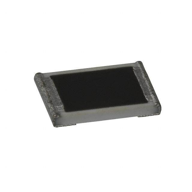
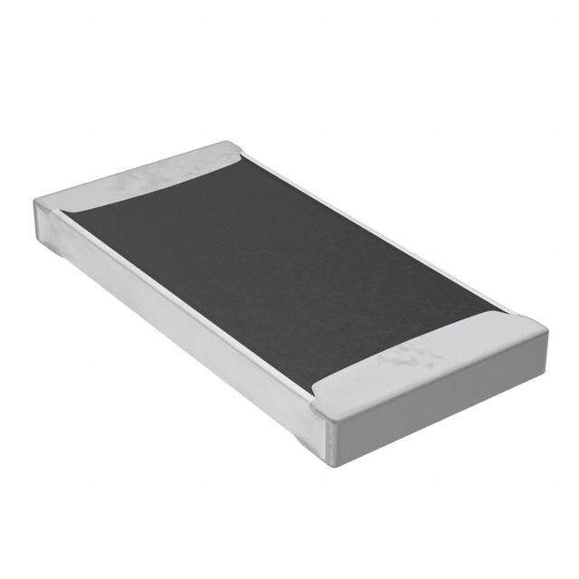
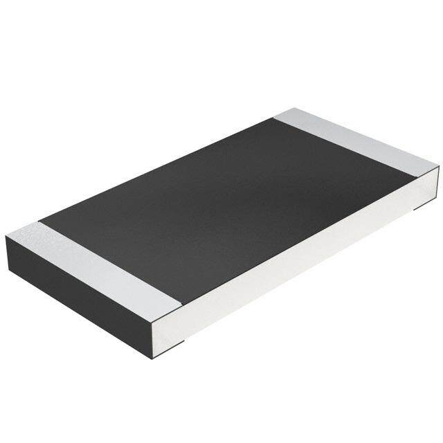
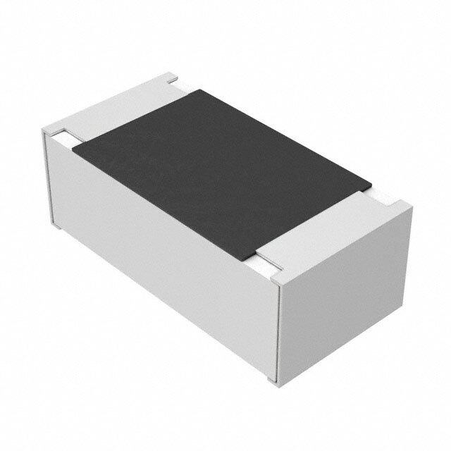
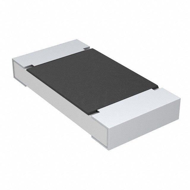
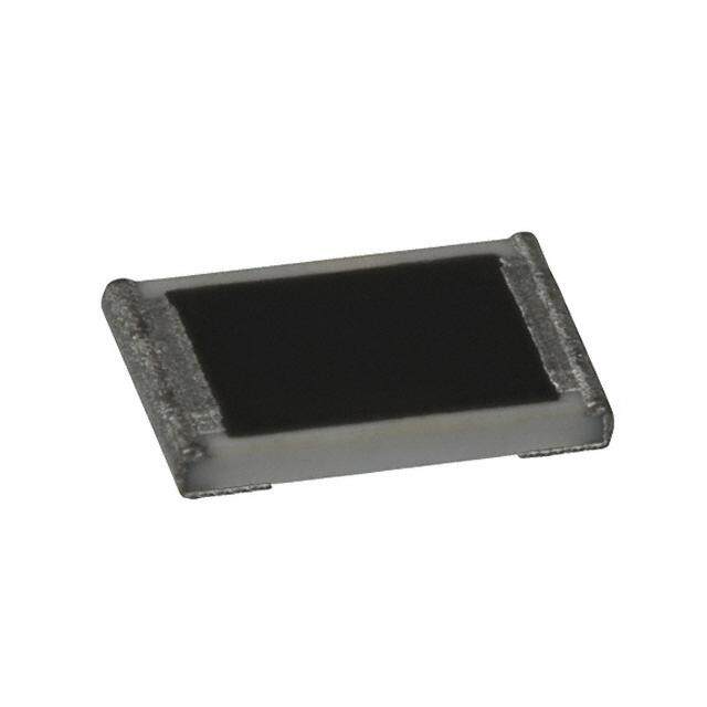
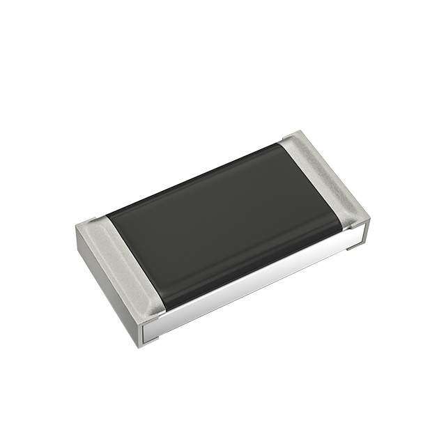
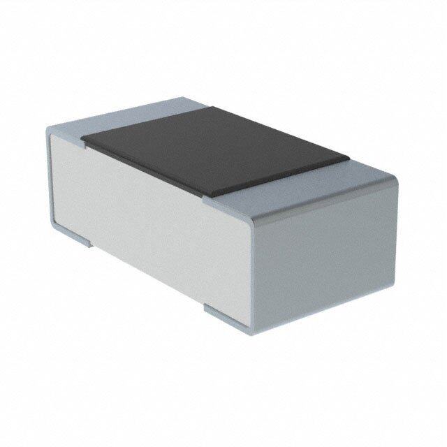
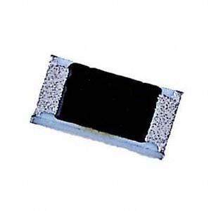
ICGOO电子元器件商城为您提供RMCF0402FT42K2由STACKPOLE ELECTRONICS INC.设计生产,在icgoo商城现货销售,并且可以通过原厂、代理商等渠道进行代购。 RMCF0402FT42K2价格参考。STACKPOLE ELECTRONICS INC.RMCF0402FT42K2封装/规格:芯片电阻 - 表面安装, 42.2 kOhms ±1% 0.063W, 1/16W Chip Resistor 0402 (1005 Metric) Automotive AEC-Q200 Thick Film。您可以下载RMCF0402FT42K2参考资料、Datasheet数据手册功能说明书,资料中有RMCF0402FT42K2 详细功能的应用电路图电压和使用方法及教程。
品牌为Stackpole Electronics Inc.、型号为RMCF0402FT42K2的芯片电阻(表面贴装型)是一款精度高、稳定性好的薄膜电阻,阻值为42.2kΩ,精度±1%,功率为1/16W(0.0625W),封装尺寸为0402(1.0mm × 0.5mm)。该电阻广泛应用于对精度和可靠性要求较高的电子设备中。

其主要应用场景包括:便携式电子产品如智能手机、平板电脑和可穿戴设备中的电源管理、信号调节与传感器接口电路;通信设备中的射频模块、基站组件和数据传输线路,用于确保信号完整性;工业控制系统的精密测量仪器、ADC/DAC转换电路和反馈回路中,提供稳定阻值;医疗电子设备如监护仪、血糖仪等对长期稳定性与低噪声有严格要求的场合;以及汽车电子中的车载信息娱乐系统、传感器模块和ECU单元,满足车规级环境下的温度与耐久性需求。

由于其采用薄膜制造工艺,RMCF0402FT42K2具有低噪声、低温漂(典型50ppm/℃)和良好的长期稳定性,适合在空间受限但性能要求高的高密度PCB设计中使用。此外,该器件符合RoHS环保标准,支持无铅焊接工艺,适用于现代自动化贴片生产流程。总体而言,该电阻适用于消费电子、工业、通信、医疗及汽车电子等多个高要求领域。
| 参数 | 数值 |
| 产品目录 | |
| 描述 | RES 42.2K OHM 1/16W 1% 0402 |
| 产品分类 | |
| 品牌 | Stackpole Electronics Inc |
| 数据手册 | |
| 产品图片 |
|
| 产品型号 | RMCF0402FT42K2 |
| PCN零件编号 | |
| rohs | 无铅 / 符合限制有害物质指令(RoHS)规范要求 |
| 产品系列 | RMCF |
| 产品目录绘图 |
|
| 供应商器件封装 | 0402 |
| 其它名称 | RMCF0402FT42K2CT |
| 功率(W) | 0.063W,1/16W |
| 包装 | 剪切带 (CT) |
| 大小/尺寸 | 0.039" 长 x 0.020" 宽(1.00mm x 0.50mm) |
| 容差 | ±1% |
| 封装/外壳 | 0402(1005 公制) |
| 工具箱 | /product-detail/zh/KIT-RMCF0402FT-05/KIT-RMCF0402FT-05-ND/3025589 |
| 成分 | 厚膜 |
| 标准包装 | 1 |
| 温度系数 | ±100ppm/°C |
| 特性 | - |
| 电阻(Ω) | 42.2k |
| 端子数 | 2 |
| 高度 | 0.016"(0.40mm) |


- 商务部:美国ITC正式对集成电路等产品启动337调查
- 曝三星4nm工艺存在良率问题 高通将骁龙8 Gen1或转产台积电
- 太阳诱电将投资9.5亿元在常州建新厂生产MLCC 预计2023年完工
- 英特尔发布欧洲新工厂建设计划 深化IDM 2.0 战略
- 台积电先进制程称霸业界 有大客户加持明年业绩稳了
- 达到5530亿美元!SIA预计今年全球半导体销售额将创下新高
- 英特尔拟将自动驾驶子公司Mobileye上市 估值或超500亿美元
- 三星加码芯片和SET,合并消费电子和移动部门,撤换高东真等 CEO
- 三星电子宣布重大人事变动 还合并消费电子和移动部门
- 海关总署:前11个月进口集成电路产品价值2.52万亿元 增长14.8%


PDF Datasheet 数据手册内容提取
RMCF / RMCP Series Stackpole Electronics, Inc. General Purpose Thick Film Standard Power and High-Power Chip Resistor Resistive Product Solutions Features: • RMCF – standard power ratings • RMCP – high power ratings • Nickel barrier terminations standard • Power derating from 100% at 70ºC to zero at +155ºC • AEC-Q200 compliant (except RMCP0201) • RoHS compliant and halogen free Electrical Specifications - RMCF Power Rating Max. M a x. M ax. Ohmic Range (Ω) and Tolerance (2) Type / Code (W) W orking O verload Jumper Current T C R ( p p m /ºC) @ 70ºC Voltage (V) (1) Voltage (V) (A) 1% 5% ± 300 10 - 97.6 RMCF01005 0.03 15 30 0.5 ± 200 100 - 1 M ± 400 1 - 9.76 RMCF0201 0.05 25 50 0.5 ± 200 10 - 10 M ± 200 1 - 9.76 (3) RMCF0402 0.063 50 100 1 ± 100 10 - 1 M ± 200 1.02 M - 10 M 1.1 M - 20 M ± 500 0.1 - 0.499 ± 400 0.5 - 0.976 RMCF0603 0.1 75 150 1 ± 200 1 - 9.76 1 - 20 M ± 100 10 - 1 M - ± 200 1.02 M - 10 M - ± 200 0.1 - 9.76 0.1 - 20 M RMCF0805 0.125 150 300 2 ± 100 10 - 1 M - ± 200 1.02 M - 10 M - ± 200 0.1 - 9.76 0.1 - 20 M RMCF1206 0.25 200 400 2 ± 100 10 - 1 M - ± 200 1.02 M - 10 M - ± 200 0.1 - 0.976 RMCF1210 0.5 200 400 3 ± 400 1 - 9.76 ± 100 10 - 10 M ± 200 0.1 - 0.976 ± 400 1 - 9.76 RMCF2010 0.75 200 400 3 ± 200 - 10 - 10 M ± 100 10 - 10 M - ± 200 0.1 - 0.976 ± 400 1 - 9.76 RMCF2512 1 200 400 3 ± 200 - 10 - 10 M ± 100 10 - 10 M - Notes: (1) Lesser of √ P*R or maximum working voltage (2) Contact Stackpole for extended ohmic values (3) Contact Stackpole for lower ohmic values Rev Date: 01/05/2021 1 www.seielect.com This specification may be changed at any time without prior notice marketing@seielect.com Please confirm technical specifications before you order and/or use.
RMCF / RMCP Series Stackpole Electronics, Inc. General Purpose Thick Film Standard Power and High-Power Chip Resistor Resistive Product Solutions Electrical Specifications - RMCP Power Rating Max. M ax. Max. Type / Code (W) Working Overload Ju mper Current T C R ( p p m /ºC) Ohmic Range (Ω) and Tolerance (2) @ 70ºC Voltage (V) (1) Voltage (V) (A) 1%, 5% -200 / +400 1 - 9.76 RMCP0201 0.063 25 50 1 ± 200 10 - 10 M ± 200 1 - 9.76 RMCP0402 0.125 50 100 1.5 ± 100 10 - 10 M ± 200 1 - 9.76 RMCP0603 0.25 75 150 2 ± 100 10 - 10 M RMCP0805 0.33 150 300 2.5 ± 200 1 - 9.76 ± 100 10 - 10 M ± 400 1 - 9.76 RMCP1206 0.5 200 400 3.5 ± 100 10 - 10 M ± 400 1 - 9.76 RMCP1210 0.66 200 400 5 ± 100 10 - 10 M RMCP2010 1 200 400 6 ± 200 1 - 9.76 ± 100 10 - 10 M ± 200 1 - 9.76 RMCP2512 2 250 500 7 ± 100 10 - 10 M Notes: (1) Lesser of √ P*R or maximum working voltage (2) Contact Stackpole for extended ohmic values Electrical Specifications - Jumper Jumper Rated Current M a x O v e r load Current J u m p e r Resistance Value Type / Code (A) (A)* (Ω) RMCP0201 0.5 1 RMCP0402 1 3 RMCP0603 1 5 RMCP0805 1 5 0.025 max. RMCP1206 2 10 RMCP1210 2 12 RMCP2010 2 12 RMCP2512 2 15 * < 1 second and 1 time Mechanical Specifications Average Unit L W H a b Type / Code Unit Weight (mg) Body Length Body Width Body Height Top Termination Bottom Termination 0.016 ± 0.0008 0.008 ± 0.0008 0.005 ± 0.0008 0.004 ± 0.0012 0.004 ± 0.0012 inches RMCF01005 0.07 0.40 ± 0.02 0.20 ± 0.02 0.13 ± 0.02 0.10 ± 0.03 0.10 ± 0.03 mm RMCF0201 0.024 ± 0.0012 0.012 ± 0.0012 0.009 ± 0.0012 0.006 ± 0.002 0.006 ± 0.002 inches 0.16 RMCP0201 0.60 ± 0.03 0.30 ± 0.03 0.23 ± 0.03 0.15 ± 0.05 0.15 ± 0.05 mm RMCF0402 0 . 5 7 0.039 ± 0.004 0.020 ± 0.002 0.012 ± 0.004 0.008 ± 0.004 0.010 ± 0.006 inches RMCP0402 0.62 1.00 ± 0.10 0.50 ± 0.05 0.30 ± 0.10 0.20 ± 0.10 0.25 ± 0.15 mm RMCF0603 1 . 8 8 0.061 ± 0.006 0.031 ± 0.006 0.018 ± 0.004 0.012 ± 0.008 0.012 ± 0.008 inches RMCP0603 2.04 1.55 ± 0.15 0.80 ± 0.15 0.45 ± 0.10 0.30 ± 0.20 0.30 ± 0.20 mm RMCF0805 5 . 0 0 0.079 ± 0.008 0.049 ± 0.004 0.020 ± 0.006 0.014 ± 0.010 0.014 ± 0.010 inches RMCP0805 4.37 2.00 ± 0.20 1.25 ± 0.10 0.50 ± 0.15 0.35 ± 0.25 0.35 ± 0.25 mm Rev Date: 01/05/2021 2 www.seielect.com This specification may be changed at any time without prior notice marketing@seielect.com Please confirm technical specifications before you order and/or use.
RMCF / RMCP Series Stackpole Electronics, Inc. General Purpose Thick Film Standard Power and High-Power Chip Resistor Resistive Product Solutions Mechanical Specifications (cont.) Average Unit L W H a b Type / Code Unit Weight (mg) Body Length Body Width Body Height Top Termination Bottom Termination RMCF1206 8 . 8 6 0.126 ± 0.010 0.063 ± 0.006 0.022 ± 0.006 0.020 ± 0.012 0.020 ± 0.012 inches RMCP1206 8.95 3.20 ± 0.25 1.60 ± 0.15 0.55 ± 0.15 0.50 ± 0.30 0.50 ± 0.30 mm RMCF1210 1 5 . 5 5 0.126 ± 0.010 0.098 ± 0.010 0.022 ± 0.006 0.020 ± 0.012 0.020 ± 0.012 inches RMCP1210 15.96 3.20 ± 0.25 2.50 ± 0.25 0.55 ± 0.15 0.50 ± 0.30 0.50 ± 0.30 mm RMCF2010 2 3 . 5 6 0.197 ± 0.008 0.098 ± 0.008 0.022 ± 0.006 0.024 ± 0.012 0.024 ± 0.014 inches RMCP2010 24.24 5.00 ± 0.20 2.50 ± 0.20 0.55 ± 0.15 0.60 ± 0.30 0.60 ± 0.35 mm RMCF2512 4 0 . 0 2 0.248 ± 0.008 0.126 ± 0.010 0.022 ± 0.006 0.024 ± 0.012 0.024 ± 0.014 inches RMCP2512 39.45 6.30 ± 0.20 3.20 ± 0.25 0.55 ± 0.15 0.60 ± 0.30 0.60 ± 0.35 mm Performance Characteristics Test Test Specifications Test Conditions (JIS-C 5202) ± (2% + 0.1Ω) 2.5 X rated voltage for 5 seconds 0201 = 1A Short Time Overload Jumper: Max 0.05Ω after test 0402 / 0603 / 0805 = 2.5A 1206 / 1210 / 2010 / 2512 = 5A Dielectric Withstanding Voltage No flashover or breakdown 100 VAC, 1 minute Resistance to Soldering Heat ± 1% 260ºC ± 5ºC, for 10 seconds ± 0.5 seconds (Solder Bath) Solderability 95% coverage, minimum 235ºC ± 5ºC, for 2 seconds ± 0.5 seconds (Colophonium flux) -65ºC: 30 minutes 25ºC: 2 to 3 minutes ± (1% + 0.05Ω) Temperature Cycle 155ºC: 30 minutes 25ºC: 2 to 3 minutes Jumper (< 0.05Ω) (5 Cycles) 1% and below: ± (1% + 0.05Ω) Load Life 2 % a n d 5 % : ± ( 3 % + 0.1Ω) 70 ± 2°C, RCWV or max. working voltage whichever is less (Endurance) Value < 1Ω: ± (3% + 0.1Ω) for 1000 hours with 1.5 hours "ON" and 0.5 hour "OFF" Jumper: Max 0.1Ω after test. 1/10 rated voltage for 3 seconds max. then rated voltage for Voltage Coefficient ± 100 (ppm/V) 3 seconds max. Robustness of Termination ± (1% + 0.05Ω) Bend of 3 mm for 5 ± 1 seconds 1%: ± (0.5% + 0.05Ω) The tested resistor should be immersed into isopropyl alcohol of Resistance to Solvent 5%: ± (0.5% + 0.05Ω) 20 ~ 25°C for 60 seconds. Then the resitor is left in the room Jumper: Max. 0.05Ω after test for 48 hours. 1%: ± (1% + 0.05Ω) 5%: ± (2% + 0.05Ω) 40 ± 2°C, 90 ~ 95% R.H. RCWV or max. working voltage whichever is Damp Heat with Load Values < 1Ω: ± (3% + 0.1Ω) less for 1000 hours with 1.5 hours "ON" and 0.5 hours "OFF" Jumper: Max. 0.1Ω after test Operating temperature range is -55°C to +155°C for all sizes except for 01005 size Operating temperature range for 01005 is -55°C to +125°C Power Derating Curve: -55ºC 70ºC 100 80 %) d ( 60 a 01005 size o er L 40 All other sizes w o P 20 125ºC 155ºC 0 -60 0 20 40 60 80 100 120 140 160 180 Ambient Temperature (ºC) Rev Date: 01/05/2021 3 www.seielect.com This specification may be changed at any time without prior notice marketing@seielect.com Please confirm technical specifications before you order and/or use.
RMCF / RMCP Series Stackpole Electronics, Inc. General Purpose Thick Film Standard Power and High-Power Chip Resistor Resistive Product Solutions Repetitive Pulse Information (This information is for reference only and is not guaranteed performance.) If repetitive pulses are applied to resistors, pulse wave form must be less than “Pulse limiting voltage”, “Pulse limiting current” or “Pulse limiting wattage” calculated by the formula below. Where: Vp: Pulse limiting voltage (V) lp: Pulse limiting current (A) Pp: Pulse limiting wattage (W) P: Power rating (W) R: Nominal resistance (ohm) T: Repetitive period (sec) t: Pulse duration (sec) K: Coefficient by resistors type (refer to below matrix) [Vr: Rated Voltage (V), Ir: Rated Current (A)] Note 1: If T > 10 → T = 10 (sec), T / t > 1000 → T / t = 1000 Note 2: If T > 10 and T / t > 1000, “Pulse Limiting power (Single pulse) is applied Note 3: If Vp < Vr (lp < lr or Pp < P), Vr (lr, P) is Vp (lp, Pp) Note 4: Pulse limiting voltage (current, wattage) is applied at less than rated ambient temperature. If ambient temperature is more than the rated temperature (70°C), please decrease power rating according to “Power Derating Curve” Note 5: Please assure sufficient margin for use period and conditions for “Pulse limiting voltage” Note 6: If the pulse waveform is not square wave, please judge after transform the waveform into square wave according to the “Waveform Transformation to Square Wave”. RMCF Coefficient (K) Matrix Resistor Type K R < 10 Ω 0.50 10 Ω ≤ R < 100 Ω 0.45 100 Ω ≤ R < 1K Ω 0.35 1K Ω ≤ R < 10K Ω 0.25 10K Ω ≤ R 0.20 Waveform Transformation to Square Wave 1. Discharge curve wave with time constant “t” → Square wave Rev Date: 01/05/2021 4 www.seielect.com This specification may be changed at any time without prior notice marketing@seielect.com Please confirm technical specifications before you order and/or use.
RMCF / RMCP Series Stackpole Electronics, Inc. General Purpose Thick Film Standard Power and High-Power Chip Resistor Resistive Product Solutions 2. Damping oscillation wave with time constant of envelope “t” → Square wave 3. Half-wave rectification wave → Square wave 4. Triangular wave → Square wave 5. Special wave → Square wave Rev Date: 01/05/2021 5 www.seielect.com This specification may be changed at any time without prior notice marketing@seielect.com Please confirm technical specifications before you order and/or use.
RMCF / RMCP Series Stackpole Electronics, Inc. General Purpose Thick Film Standard Power and High-Power Chip Resistor Resistive Product Solutions Recommended Pad Layout Size A B C Unit 0.008 0.020 0.008 inches 01005 0.20 0.50 0.20 mm 0.012 0.039 0.016 inches 0201 0.30 1.00 0.40 mm 0.020 0.059 0.024 inches 0402 0.50 1.50 0.60 mm 0.031 0.083 0.035 inches 0603 0.80 2.10 0.90 mm 0.047 0.118 0.051 inches 0805 1.20 3.00 1.30 mm 0.087 0.165 0.063 inches 1206 2.20 4.20 1.60 mm 0.087 0.165 0.110 inches 1210 2.20 4.20 2.80 mm 0.138 0.240 0.110 inches 2010 3.50 6.10 2.80 mm 0.193 0.315 0.138 inches 2512 4.90 8.00 3.50 mm Recommended Solder Profile This information is intended as a reference for solder profiles for Stackpole resistive components. These profiles should be compatible with most soldering processes. These are only recommendations. Actual numbers will depend on board density, geometry, packages used, etc., especially those cells labeled with “*”. 100% Matte Tin / RoHS Compliant Terminations Soldering iron recommended temperatures: 330°C to 350°C with minimum duration. Maximum number of reflow cycles: 3. Wave Soldering Description Maximum Recommended Minimum Preheat Time 80 seconds 70 seconds 60 seconds Temperature Diff. 140°C 120°C 100°C Solder Temp. 260°C 250°C 240°C Dwell Time at Max. 10 seconds 5 seconds * Ramp DN (°C/sec) N/A N/A N/A Temperature Diff. = Defference between final preheat stage and soldering stage. Rev Date: 01/05/2021 6 www.seielect.com This specification may be changed at any time without prior notice marketing@seielect.com Please confirm technical specifications before you order and/or use.
RMCF / RMCP Series Stackpole Electronics, Inc. General Purpose Thick Film Standard Power and High-Power Chip Resistor Resistive Product Solutions Convection IR Reflow Description Maximum Recommended Minimum Ramp Up (°C/sec) 3°C/sec 2°C/sec * Dwell Time > 217°C 150 seconds 90 seconds 60 seconds Solder Temp. 260°C 245°C * Dwell Time at Max. 30 seconds 15 seconds 10 seconds Ramp DN (°C/sec) 6°C/sec 3°C/sec * Recommended Lead Free Resistor Reflow Profile Packaging (EIA Standard RS-481) Packaging Specifications Reel Type Wa M A B C D Unit 7" reel for 0 . 3 5 4 ± 0.020 7.008 ± 0.079 0.079 ± 0.020 0.531 ± 0.020 0.827 ± 0.020 2.362 ± 0.039 inches 8 mm tape 9.00 ± 0.50 178.00 ± 2.00 2.00 ± 0.50 13.50 ± 0.50 21.00 ± 0.50 60.00 ± 1.00 mm 10" reel for 0 . 3 9 4 ± 0.020 10.000 ± 0.079 0.079 ± 0.020 0.531 ± 0.020 0.827 ± 0.020 3.937 ± 0.039 inches 8 mm tape 10.00 ± 0.50 254.00 ± 2.00 2.00 ± 0.50 13.50 ± 0.50 21.00 ± 0.50 100.00 ± 1.00 mm Rev Date: 01/05/2021 7 www.seielect.com This specification may be changed at any time without prior notice marketing@seielect.com Please confirm technical specifications before you order and/or use.
RMCF / RMCP Series Stackpole Electronics, Inc. General Purpose Thick Film Standard Power and High-Power Chip Resistor Resistive Product Solutions Taping Specifications - 01005, 0201, 0402 7" Reel Typical Full Tape Size A B W E F Unit Quantity R e e l W eight (g) Width 0.315 0.018 ± 0.001 0.010 ± 0.001 0.315 ± 0.012 0.069 ± 0.004 0.138 ± 0.002 inches 01005 10000 127.3 ± 12.0 8.00 0.45 ± 0.02 0.25 ± 0.02 8.00 ± 0.30 1.75 ± 0.10 3.50 ± 0.05 mm 0.315 0.028 ± 0.006 0.016 ± 0.006 0.315 ± 0.008 0.069 ± 0.004 0.138 ± 0.002 inches 0201 10000 97.2 ± 9.0 8.00 0.70 ± 0.15 0.40 ± 0.15 8.00 ± 0.20 1.75 ± 0.10 3.50 ± 0.05 mm 0.315 0.047 ± 0.006 0.028 ± 0.006 0.315 ± 0.008 0.069 ± 0.004 0.138 ± 0.002 inches 0402 10000 94.5 ± 9.0 8.00 1.20 ± 0.15 0.70 ± 0.15 8.00 ± 0.20 1.75 ± 0.10 3.50 ± 0.05 mm Size T1 T2 P P0 P1 Unit 01005 0.012 ± 0.001 0.007 ± 0.001 0.079 ± 0.002 0.157 ± 0.002 0.079 ± 0.002 inches 0.31 ± 0.03 0.17 ± 0.03 2.00 ± 0.05 4.00 ± 0.05 2.00 ± 0.05 mm 0.015 ± 0.006 0.011 ± 0.001 0.079 ± 0.004 0.157 ± 0.004 0.079 ± 0.002 inches 0201 0.38 ± 0.15 0.28 ± 0.02 2.00 ± 0.10 4.00 ± 0.10 2.00 ± 0.05 mm 0.016 ± 0.008 0.016 ± 0.002 0.079 ± 0.004 0.157 ± 0.004 0.079 ± 0.002 inches 0402 0.40 ± 0.20 0.40 ± 0.05 2.00 ± 0.10 4.00 ± 0.10 2.00 ± 0.05 mm Taping Specifications - 0603, 0805, 1206, 1210 7" Reel Typical Full Reel Size Tape Width A B W E Unit Quantity (1) Weight (g) 0.315 0.071 ± 0.008 0.041 ± 0.008 0.315 ± 0.008 0.069 ± 0.004 inches 0603 5000 118.3 ± 11.0 8.00 1.80 ± 0.20 1.05 ± 0.20 8.00 ± 0.20 1.75 ± 0.10 mm 0.315 0.093 ± 0.010 0.063 ± 0.010 0.315 ± 0.008 0.069 ± 0.004 inches 0805 5000 139.2 ± 13.0 8.00 2.35 ± 0.25 1.60 ± 0.25 8.00 ± 0.20 1.75 ± 0.10 mm 0.315 0.140 ± 0.010 0.077 ± 0.010 0.315 ± 0.008 0.069 ± 0.004 inches 1206 5000 151.4 ± 15.0 8.00 3.55 ± 0.25 1.95 ± 0.25 8.00 ± 0.20 1.75 ± 0.10 mm 0.315 0.138 ± 0.008 0.110 ± 0.010 0.315 ± 0.008 0.069 ± 0.004 inches 1210 4000 175.7 ± 17.0 8.00 3.50 ± 0.20 2.80 ± 0.25 8.00 ± 0.20 1.75 ± 0.10 mm Rev Date: 01/05/2021 8 www.seielect.com This specification may be changed at any time without prior notice marketing@seielect.com Please confirm technical specifications before you order and/or use.
RMCF / RMCP Series Stackpole Electronics, Inc. General Purpose Thick Film Standard Power and High-Power Chip Resistor Resistive Product Solutions Taping Specifications - 0603, 0805, 1206, 1210 (cont.) Size F T1 T2 P P0 P1 Unit 0.138 ± 0.002 0.024 ± 0.008 0.024 ± 0.004 0.157 ± 0.004 0.157 ± 0.004 0.079 ± 0.002 inches 0603 3.50 ± 0.05 0.60 ± 0.20 0.60 ± 0.10 4.00 ± 0.10 4.00 ± 0.10 2.00 ± 0.05 mm 0.138 ± 0.002 0.030 ± 0.008 0.030 ± 0.004 0.157 ± 0.004 0.157 ± 0.004 0.079 ± 0.002 inches 0805 3.50 ± 0.05 0.75 ± 0.20 0.75 ± 0.10 4.00 ± 0.10 4.00 ± 0.10 2.00 ± 0.05 mm 0.138 ± 0.002 0.030 ± 0.008 0.030 ± 0.004 0.157 ± 0.004 0.157 ± 0.004 0.079 ± 0.002 inches 1206 3.50 ± 0.05 0.75 ± 0.20 0.75 ± 0.10 4.00 ± 0.10 4.00 ± 0.10 2.00 ± 0.05 mm 0.138 ± 0.002 0.030 ± 0.008 0.030 ± 0.004 0.157 ± 0.004 0.157 ± 0.004 0.079 ± 0.002 inches 1210 3.50 ± 0.05 0.75 ± 0.20 0.75 ± 0.10 4.00 ± 0.10 4.00 ± 0.10 2.00 ± 0.05 mm Taping Specifications - 2010, 2512 7" Reel Typical Full Reel Tape Size A B W E F Unit Quantity Weight (g) Width 0.472 0.217 ± 0.012 0.110 ± 0.008 0.472 ± 0.008 0.069 ± 0.004 0.217 ± 0.002 inches 2010 4000 183.1 ± 18.0 12.00 5.50 ± 0.30 2.80 ± 0.20 12.00 ± 0.20 1.75 ± 0.10 5.50 ± 0.05 mm 0.472 0.264 ± 0.008 0.134 ± 0.008 0.472 ± 0.008 0.069 ± 0.004 0.217 ± 0.002 inches 2512 4000 255.3 ± 25.0 12.00 6.70 ± 0.20 3.40 ± 0.20 12.00 ± 0.20 1.75 ± 0.10 5.50 ± 0.05 mm Size T1 T2 P P0 P1 Unit 0.041 ± 0.008 0.009 ± 0.006 0.157 ± 0.004 0.157 ± 0.004 0.079 ± 0.002 inches 2010 1.05 ± 0.20 0.23 ± 0.15 4.00 ± 0.10 4.00 ± 0.10 2.00 ± 0.05 mm 0.041 ± 0.008 0.009 ± 0.006 0.157 ± 0.004 0.157 ± 0.004 0.079 ± 0.002 inches 2512 1.05 ± 0.20 0.23 ± 0.15 4.00 ± 0.10 4.00 ± 0.10 2.00 ± 0.05 mm Note: Plastic carrier tape used for 2010 and 2512 sizes. Rev Date: 01/05/2021 9 www.seielect.com This specification may be changed at any time without prior notice marketing@seielect.com Please confirm technical specifications before you order and/or use.
RMCF / RMCP Series Stackpole Electronics, Inc. General Purpose Thick Film Standard Power and High-Power Chip Resistor Resistive Product Solutions Single Pulse Power 1000 s) 100 att W er ( w Po RMCF2512 10 RMCF2010 RMCF1210 RMCF1206 RMCF0805 1 RMCF0603 0.0001 0.001 0.01 0.1 RMCF0402 1 Time (s) Time (s) Size Unit 0.0001 0.001 0.01 0.1 1 0402 60 18 6.3 2.2 0.7 W Single Pulse Power (cont.) Time (s) Size Unit 0.0001 0.001 0.01 0.1 1 0603 70 21.5 7.6 2.8 1 W 0805 94 34 12 4.4 1.6 W 1206 120 43 15 5.6 2 W 1210 240 86 31 11 4 W 2010 210 96 41 18 8 W 2512 800 300 110 42 16 W The data provided are for reference only. They are typical performance for this product but are not guaranteed. The actual pulse handling of each individual resistor may vary depending on a variety of factors including resistance tolerance and resistance value. Stackpole Electronics, Inc. assumes no liability for the use of this information. Customers should validate the performance of these products in their applications. Contact Stackpole marketing to discuss specific pulse application requirements. Temperature Measurement of Resistor Surface Description: The resistor surface generated temperature variation after applied rated voltage. Products and power: Size 0201 0402 0603 0805 1206 1210 2010 2512 R-V 15K 40.2K 57.6K 180K 182K 100K 100K 75K Rated Power (W) 1/20 1/16 1/10 1/8 1/4 1/2 3.4 1 Max Rated Voltage (V) 25 50 75 150 200 200 200 200 Test method: Measure component surface temperature directly after the temperature stabilizes. Rev Date: 01/05/2021 10 www.seielect.com This specification may be changed at any time without prior notice marketing@seielect.com Please confirm technical specifications before you order and/or use.
RMCF / RMCP Series Stackpole Electronics, Inc. General Purpose Thick Film Standard Power and High-Power Chip Resistor Resistive Product Solutions Test result: As per table below: Hot Spot Temperature - RMCF Size 0201 0402 0603 0805 1206 1210 2010 2512 Surface Temp. (°C) 36 37 46.2 50.4 70.6 110.6 141 150.4 The thermal resistance of the RMCP will be similar to the RMCF. For example, the RMCF2512 and the RMCP2512 will have similar surface temperatures at 1W; the RMCP is designed to withstand higher temperatures associated with high power levels. Part Marking Specifications 5% Marking 1% Marking The nominal resistance is marked on The nominal resistance is marked on the surface of the overcoating with the the surface of the overcoating with the use of 3 digit markings. use of 4 digit markings. 0201 and 0402 are not marked. 0201 and 0402 are not marked. For shared E24/E96 values, 1% tolerance product may be marked with three digit marking instead of the standard four digit marking for all other E96 values. All E24 values available in 1% tolerance are also marked with three digit marking. Mark Instructions for 0603 1% Chip Resistors (per EIA-J) A two-digit number is assigned to each standard R-Value (E96) as shown in the chart below. This is followed by one alpha character which is used as a multiplier. Each letter “Y” – “F” represents a specific multiplier as follows: Y = 0.1 X = 1 A = 10 B = 100 C = 1000 D(d) = 10000 E = 100000 F = 1000000 Rev Date: 01/05/2021 11 www.seielect.com This specification may be changed at any time without prior notice marketing@seielect.com Please confirm technical specifications before you order and/or use.
RMCF / RMCP Series Stackpole Electronics, Inc. General Purpose Thick Film Standard Power and High-Power Chip Resistor Resistive Product Solutions EXAMPLE: Chip Marking Explanation Value 01B 01 means 10.0 and B = 100 10.0 x 100 = 1 K ohm 25C 25 means 17.8 and C = 1,000 17.8 x 1,000 = 17.8 K ohm 93D 93 means 90.9 and D = 10,000 90.9 x 10,000 = 909 K ohm E96 1% # 1% # 1% # 1% # 1% # 1% # 10.0 01 14.7 17 21.5 33 31.6 49 46.4 65 68.1 81 10.2 02 15.0 18 22.1 34 32.4 50 47.5 66 69.8 82 10.5 03 15.4 19 22.6 35 33.2 51 48.7 67 71.5 83 10.7 04 15.8 20 23.2 36 34.0 52 49.9 68 73.2 84 11.0 05 16.2 21 23.7 37 34.8 53 51.1 69 75.0 85 11.3 06 16.5 22 24.3 38 35.7 54 52.3 70 76.8 86 11.5 07 16.9 23 24.9 39 36.5 55 53.6 71 78.7 87 11.8 08 17.4 24 25.5 40 37.4 56 54.9 72 80.6 88 12.1 09 17.8 25 26.1 41 38.3 57 56.2 73 82.5 89 12.4 10 18.2 26 26.7 42 39.2 58 57.6 74 84.5 90 12.7 11 18.7 27 27.4 43 40.2 59 59.0 75 86.6 91 13.0 12 19.1 28 28.0 44 41.2 60 60.4 76 88.7 92 13.3 13 19.6 29 28.7 45 42.2 61 61.9 77 90.9 93 13.7 14 20.0 30 29.4 46 43.2 62 63.4 78 93.1 94 14.0 15 20.5 31 30.1 47 44.2 63 64.9 79 95.3 95 14.3 16 21.0 32 30.9 48 45.3 64 66.5 80 97.6 96 RoHS Compliance Stackpole Electronics has joined the worldwide effort to reduce the amount of lead in electronic components and to meet the various regulatory requirements now prevalent, such as the European Union’s directive regarding “Restrictions on Hazardous Substances” (RoHS 3). As part of this ongoing program, we periodically update this document with the status regarding the availability of our compliant components. All our standard part numbers are compliant to EU Directive 2011/65/EU of the European Parliament as amended by Directive (EU) 2015/863/EU as regards the list of restricted substances. RoHS Compliance Status Standard Lead-Free Standard Package / Lead-Free Series Lead-Free Termination Effective Date Product Description Termination Mfg. Effective Date RoHS Composition Code Series Type (Std Product Series) Compliant (YY/WW) General Purpose Thick Film Jan-04 (Japan) 0 4 / 0 1 RMCF SMD YES(1) 100% Matte Sn over Ni Surface Mount Chip Resistor Jan-05 (Taiwan, China) 05/01 RMCP General Purpose High Power S M D YES(1) 100% Matte Sn over Ni Always Always Thick Film Chip Resistor Note (1): RoHS Compliant by means of exemption 7c-I. “Conflict Metals” Commitment We at Stackpole Electronics, Inc. are joined with our industry in opposing the use of metals mined in the “conflict region” of the eastern Democratic Republic of the Congo (DRC) in our products. Recognizing that the supply chain for metals used in the electronics industry is very complex, we work closely with our own suppliers to verify to the extent possible that the materials and products we supply do not contain metals sourced from this conflict region. As such, we are in compliance with the requirements of Dodd-Frank Act regarding Conflict Minerals. Rev Date: 01/05/2021 12 www.seielect.com This specification may be changed at any time without prior notice marketing@seielect.com Please confirm technical specifications before you order and/or use.
RMCF / RMCP Series Stackpole Electronics, Inc. General Purpose Thick Film Standard Power and High-Power Chip Resistor Resistive Product Solutions Compliance to “REACH” We certify that all passive components supplied by Stackpole Electronics, Inc. are SVHC (Substances of Very High Concern) free and compliant with the requirements of EU Directive 1907/2006/EC, “The Registration, Evaluation, Authorization and Restriction of Chemicals”, otherwise referred to as REACH. Contact us for complete list of REACH Substance Candidate List. Environmental Policy It is the policy of Stackpole Electronics, Inc. (SEI) to protect the environment in all localities in which we operate. We continually strive to improve our effect on the environment. We observe all applicable laws and regulations regarding the protection of our environment and all requests related to the environment to which we have agreed. We are committed to the prevention of all forms of pollution. How to Order - RMCF 1 2 3 4 5 6 7 8 9 10 11 12 13 14 R M C F 0 6 0 3 J T 4 K 7 0 Product Series Size Tolerance Packaging Resistance Value Code Description Size W Code Tol Value Code Description Size Quantity Four characters with the Thick Film 0 1 0 0 5 0.03 F 1% E96, E24 01005 10000 multiplier used as the RMCF Chip 0201 0.05 J 5% E24 7" Reel - Paper 0201, 0402 10000 decimal holder. 0402 0.063 Z Jumper Tape 0603, 0805, 1206 5000 0.1 ohm = R100 T 0603 0.1 1210 4000 4.70 ohm = 4R70 0805 0.125 7" Reel - 10.0 Kohm = 10K0 2010, 2512 4000 1206 0.25 Plastic Tape 1 Mohm = 1M00 1210 0.5 10" Reel - Zero ohm jumper = 0R00 G 0603, 0805, 1206 10000 2010 0.75 Paper Tape 2512 1 How to Order - RMCP 1 2 3 4 5 6 7 8 9 10 11 12 13 14 R M C P 0 6 0 3 J T 4 K 7 0 Product Series Size Tolerance Packaging Resistance Value Code Description Size W Code Tol Value Code Description Size Quantity Four characters with the RMCP High Power 0201 0.063 F 1% E96, E24 0201, 0402 10000 multiplier used as the 0402 0.125 J 5% E24 7" Reel 0 6 03, 0805 decimal holder. T 5000 0603 0.25 Z Jumper Paper Tape 1206, 1210 1 ohm = 1R00 0805 0.33 2010, 2512 4000 10 Kohm = 10K0 1206 0.5 0603, 0805 1 Mohm = 1M00 10" Reel 10000 1210 0.66 G 1206, 1210 Paper Tape 2010 1 2010 8000 2512 2 Rev Date: 01/05/2021 13 www.seielect.com This specification may be changed at any time without prior notice marketing@seielect.com Please confirm technical specifications before you order and/or use.