ICGOO在线商城 > 电阻器 > 芯片电阻 - 表面安装 > RLP73K3AR24FTDF
 Datasheet下载
- 型号: RLP73K3AR24FTDF
- 制造商: CORCOM/TYCO ELECTRONICS
- 库位|库存: xxxx|xxxx
- 要求:
| 数量阶梯 | 香港交货 | 国内含税 |
| +xxxx | $xxxx | ¥xxxx |
查看当月历史价格
查看今年历史价格
RLP73K3AR24FTDF产品简介:
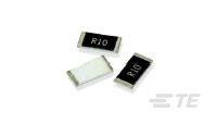
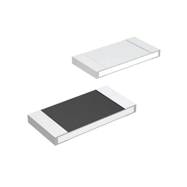
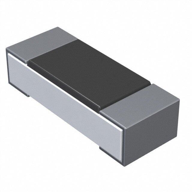
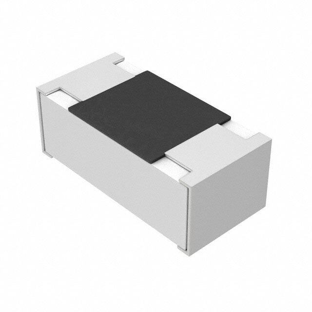
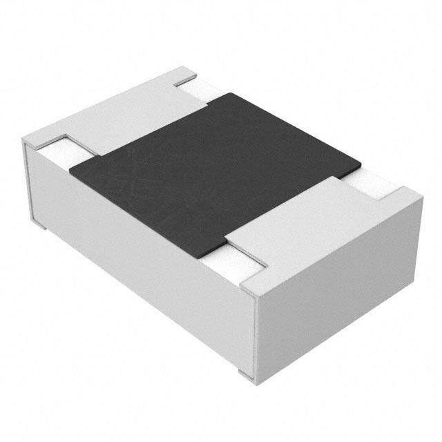
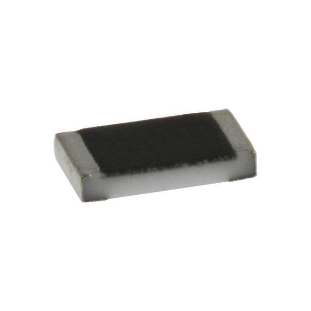
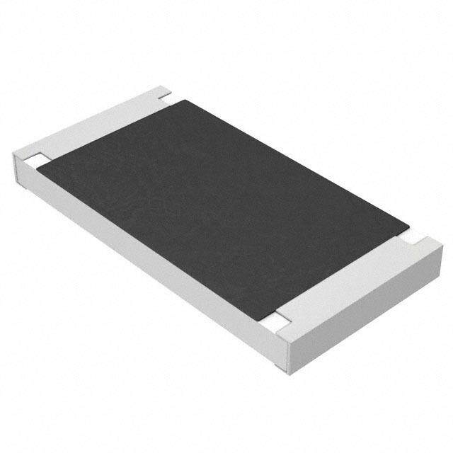
ICGOO电子元器件商城为您提供RLP73K3AR24FTDF由CORCOM/TYCO ELECTRONICS设计生产,在icgoo商城现货销售,并且可以通过原厂、代理商等渠道进行代购。 RLP73K3AR24FTDF价格参考。CORCOM/TYCO ELECTRONICSRLP73K3AR24FTDF封装/规格:芯片电阻 - 表面安装, 240 mOhms ±1% 2W 厚膜 芯片电阻 2512(6432 公制) 电流检测 厚膜。您可以下载RLP73K3AR24FTDF参考资料、Datasheet数据手册功能说明书,资料中有RLP73K3AR24FTDF 详细功能的应用电路图电压和使用方法及教程。
RLP73K3AR24FTDF 是 TE Connectivity 推出的一款表面贴装芯片电阻,广泛应用于对性能和可靠性要求较高的电子设备中。该电阻具有高精度、低温漂、优异的长期稳定性以及良好的耐湿热性能,适用于以下典型应用场景:

1. 工业控制设备:如PLC(可编程逻辑控制器)、传感器模块、工业自动化系统等,适用于复杂工业环境,确保系统稳定运行。

2. 通信设备:用于基站、光模块、路由器和交换机等通信基础设施中,提供稳定的信号处理和电源管理支持。

3. 汽车电子系统:符合AEC-Q200标准,适用于车载控制单元(ECU)、车载娱乐系统、电池管理系统(BMS)等,满足汽车环境对温度和可靠性的严苛要求。

4. 消费类电子产品:如智能手机、平板电脑、可穿戴设备等,适用于高密度贴装需求,有助于缩小产品体积并提升整体性能。

5. 电源管理模块:适用于DC-DC转换器、AC-DC电源、稳压器等电源相关设计,具备良好的热稳定性和负载能力。

6. 医疗电子设备:用于便携式或精密医疗仪器中,确保长期使用中的测量精度和稳定性。

该电阻采用高可靠性薄膜工艺,尺寸为0805或相近封装,适用于自动贴片工艺,便于大批量生产。其F级精度(±1%)和低温度系数(±50ppm/℃),使其在精密测量和控制电路中表现出色。
| 参数 | 数值 |
| 产品目录 | |
| 描述 | RES 0.24 OHM 2W 1% 2512 |
| 产品分类 | |
| 品牌 | TE Connectivity |
| 数据手册 | http://www.te.com/commerce/DocumentDelivery/DDEController?Action=srchrtrv&DocNm=2176057&DocType=Customer+Drawing&DocLang=English |
| 产品图片 |
|
| 产品型号 | 3-2176057-4 |
| rohs | 无铅 / 符合限制有害物质指令(RoHS)规范要求 |
| 产品系列 | RL73, CGS |
| 供应商器件封装 | 2512 |
| 其它名称 | A109703DKR |
| 功率(W) | 2W |
| 包装 | Digi-Reel® |
| 大小/尺寸 | 0.250" 长 x 0.124" 宽(6.35mm x 3.15mm) |
| 容差 | ±1% |
| 封装/外壳 | 2512(6432 公制) |
| 成分 | 厚膜 |
| 标准包装 | 1 |
| 温度系数 | ±200ppm/°C |
| 特性 | 电流检测 |
| 电阻(Ω) | 0.24 |
| 端子数 | 2 |
| 高度 | 0.033"(0.84mm) |
.jpg)


PDF Datasheet 数据手册内容提取
SMD Low Ohmic – Current Sense Resistors Type RL73 Series Key Features Up to 2W @ 70°C 8 chip sizes Ideal for current detection Terminal finish – electroplated 100% matte Sn Applications Communications Audio Automotive Low voltage power TE Connectivity are pleased to offer this thick film chip resistor for supplies current sensing positions. It has a special metal glaze resistive element and a nickel barrier layer beneath the solder to prolong terminal life. Power management Following the developments by semiconductor manufacturers in the applications production of a range of IC's for battery charge management and low voltage power supplies, the RL73 Series satisfies the demand for a low ohmic shunt resistor to act as a current sensor. Electrical Characteristics Standard Power Power Max Packaging TCR Resistance Size Size rating @ Operating (PPM/°C) Range (Ω) TDF TD TE Tape 70°C Current RL73X1H ±1000 R10 – R13 RL73V1H 0201 ±600 0.05W R15 – R47 0.70A 1000 5000 Paper RL73N1H ±300 R51 – R91 RL73M1E ±400 R05 – R091 RL73N1E 0402 ±300 0.0625W R10 – R47 1.11A 1000 5000 Paper RL73K1E ±200 R51 – R91 RL73V1J ±600 R020 – R047 RL73M1J ±400 R051 – R091 0603 0.1W 2.23A 1000 5000 Paper RL73N1J ±300 R10 – R50 RL73K1J ±200 R51 – R91 RL73V2A ±600 R020 – R047 RL73M2A ±400 R051 – R10 2.50A RL73N2A 0805 ±300 0.125W R11 – R18 1000 5000 Paper RL73K2A ±200 R20 – R91 RL73H2A ±100 R10 – R91 1.11A 17 73269 REV H 12/2018 Dimensions in Dimensions Shown for For Email, phone or live chat, millimetres unless reference purposes only. go to: www.te.com/help otherwise specified Specifications subject to change
SMD Low Ohmic – Current Sense Resistors Electrical Characteristics Standard Power (continued) Power Max Packaging TCR Resistance Size Size rating @ Operating (PPM/°C) Range (Ω) TDF TD TE Tape 70°C Current RL73V2B ±600 R010 – R020 RL73M2B ±400 R022 – R047 5.00A RL73N2B 1206 ±300 0.25W R051 – R091 1000 5000 Paper RL73K2B ±200 R10 – R91 RL73H2B ±100 R10 – R91 1.58A RL73V2E ±600 R010 – R020 RL73M2E ±400 R022 – R047 7.07A RL73N2E 1210 ±300 0.5W R051 – R091 1000 5000 Paper RL73K2E ±200 R10 – R91 RL73H2E ±100 R075 – R91 2.58A RL73V2H ±600 R010 – R020 RL73M2H ±400 R022 – R047 8.66A Embossed RL73N2H 2010 ±300 0.75W R051 – R091 4000 Plastic RL73K2H ±200 R10 – R91 RL73H2H ±100 R050 – R91 3.87A RL73V3A ±600 R010 – R020 RL73M3A ±400 R022 – R047 10.0A Embossed RL73N3A 2512 ±300 1W R051 – R091 4000 Plastic RL73K3A ±200 R10 – R91 RL73H3A ±100 R020 – R91 7.07A Characteristics Electrical – High Power Version - RLP73 Max. Packaging TCR Power Resistance Type Size Operating (PPM/°C) rating Range TDF TD TE Tape current RLP73M1E ±400 R051 – R091 RLP73N1E 0402 ±300 0.125W R10 – R47 1.56A 1000 5000 Paper RLP73K1E ±200 R51 – R91 RLP73M1J ±400 R051 – R091 RLP73N1J 0603 ±300 0.125W R10– R47 1.98A 1000 5000 Paper RLP73K1J ±200 R51 – R91 RLP73M2A ±400 R051 – R091 RLP73N2A 0805 ±300 0.25W R10 – R47 2.21A 1000 5000 Paper RLP73K2A ±200 R51 – R91 RLP73V2B ±600 R010 – R020 RLP73M2B ±400 R022 – R047 1206 0.5W 7.07 1000 5000 Paper RLP73N2B ±300 R051 – R091 RLP73K2B ±200 R10 – R91 1773269 REV H 12/2018 Dimensions in Dimensions Shown for For Email, phone or live chat, millimetres unless reference purposes only. go to: www.te.com/help otherwise specified Specifications subject to change
SMD Low Ohmic – Current Sense Resistors Characteristics Electrical – High Power Version - RLP73 (continued) Max. Packaging TCR Power Resistance Type Size Operating (PPM/°C) rating Range TDF TD TE Tape current RLP73V2E 1210 ±600 0.75W R010 – R020 8.66A 1000 5000 Paper RLP73M2E ±400 R022 – R047 RLP73N2E ±300 R051 – R091 RLP73K2E ±200 R10 – R91 RLP73V2H 2010 ±600 1W R010 – R020 10A 1000 4000 Embossed RLP73M2H ±400 R022 – R047 Plastic RLP73N2H ±300 R051 – R091 RLP73K2H ±200 R10 – R91 RLP73V3A 2512 ±600 2W R010 – R020 14.1A 1000 4000 Embossed RLP73M3A ±400 R022 – R047 Plastic RLP73N3A ±300 R051 – R091 RLP73K3A ±200 R10 – R91 Operating Voltage=√(P*R) ; Overload Voltage=2.5*√(P*R) ; Operating Current=√(P/R) Maximum operating temperature -55°C to +155°C Storage Temperature 25±3°C; Humidity < 80%RH Power Derating curve For resistors operated in ambient temperatures above 70°C, power rating must be derated in accordance with this curve. 1773269 REV H 12/2018 Dimensions in Dimensions Shown for For Email, phone or live chat, millimetres unless reference purposes only. go to: www.te.com/help otherwise specified Specifications subject to change
SMD Low Ohmic – Current Sense Resistors Construction and dimensions Alumina Substrate Edge Electrode (NiCr) Resistor Layer (Ag/Pd) Bottom Electrode (Ag) Barrier Layer (Ni) Primary Overcoat (Glass) Top Electrode (Ag-Pd) External Electrode (Sn) Secondary Overcoat (Epoxy) Weight (g) Type Size L (mm) W (mm) T (mm) D1 (mm) D2 (mm) (1000 Pcs.) RL73 0201 (1H) 0.60±0.03 0.30±0.03 0.23±0.05 0.12±0.05 0.15±0.05 0.18 RL73 / 0402 (1E) 1.00±0.05 0.50±0.05 0.32±0.10 0.25±0.10 0.20±0.10 0.7 RLP73 RL73 / 0603 (1J) 1.60±0.10 0.80±0.10 0.45±0.10 0.30±0.20 0.30±0.20 1.99 RLP73 RL73 / 0805 (2A) 2.00±0.10 1.25±0.10 0.55±0.10 0.30±0.20 0.40±0.25 5.3 RLP73 RL73 / 1206 (2B) 3.10±0.10 1.55±0.10 0.55±0.10 0.50±0.30 0.40±0.25 8.82 RLP73 RL73 / 1210 (2E) 3.10±0.10 2.60±0.15 0.55±0.10 0.50±0.30 0.50±0.25 15.5 RLP73 RL73 / 2010 (2H) 5.00±0.10 2.50±0.15 0.60±0.15 0.60±0.30 0.50±0.25 27.03 RLP73 RL73 2512 (3A) 6.35±0.10 3.10±0.15 0.60±0.10 0.60±0.30 0.55±0.25 43.08 2512 (3A) RLP73 6.35±0.20 3.15±0.15 0.74±0.10 0.60±0.30 0.55±0.25 53.08 (R010-R099) 2512 (3A) RLP73 6.35±0.20 3.15±0.15 0.74±0.10 0.60±0.30 2.10±0.10 53.08 (R10 -R91) Suggested PCB Layout Plan Type A (mm) B (mm) C ±0.2mm 0201 0.25 0.30 0.40 0402 0.50 0.50 0.60 0603 0.80 1.00 0.90 0805 1.00 1.00 1.35 1206 2.00 1.15 1.70 1210 2.00 1.15 2.50 2010 3.60 1.40 2.50 2512 (1W) 4.90 1.60 3.20 2512 (2W) ≤99mΩ 4.90 1.60 3.20 2512 (2W) ≥100mΩ 1.0 3.55 3.20 1773269 REV H 12/2018 Dimensions in Dim ensions Shown for For Email, phone or live chat, millimetres unless reference purposes only. go to: www.te.com/help otherwise specified Specifications subject to change
SMD Low Ohmic – Current Sense Resistors Solder Profile (1) Time of IR reflow soldering at maximum temperature point 260°C:10s (2) Time of wave soldering at maximum temperature point 260°C : 10s (3) Time of soldering iron at maximum temperature point 410°C : 5s Marking Specification For 0201 and 0402 size resistor – No Marking 1% & 5% 0805/1206/1210/2010/2512 size Resistors – 4 Digit Marking. Example: Resistance 47mΩ 75mΩ 15mΩ 750mΩ 820mΩ Marking R047 R075 R015 R750 R820 5% for 0603: 3 digits marking in E24 1% for 0603: 3 digits marking with under-line in E96 (if value appears in both E96 and E24 refer to E24) R10 3 digits marking for E24 or R value suffix is zero in E96: R10=100mΩ; R28=280mΩ 243 3 digits marking for E96: 243=243mΩ; 511=511mΩ 047 3 digit marking for E24 where value is less than 100mΩ and R value suffix is NOT 0; E.G. R047=47mΩ 1773269 REV H 12/2018 Dimensions in Dimensions Shown for For Email, phone or live chat, millimetres unless reference purposes only. go to: www.te.com/help otherwise specified Specifications subject to change
SMD Low Ohmic – Current Sense Resistors Environmental Characteristics Item Requirement Test Method JIS-C-5201-1 4.8 Temperature Coefficient of IEC-60115-1 4.8 As Spec. Resistance (TCR) -55°C ~+125°C, 25°C is the reference temperature JIS C 5201-1 4.13 ±(0.5%+0.05Ω) IEC 60115-1 4.13 Short Time Overload RCWV*2.5 or Max. Overload ±(1.0%+0.05Ω) Voltage whichever is lower for 5 For High power rating seconds JIS-C-5201-1 4.6 IEC-60115-1 4.6 Insulation Resistance ≥10G Max. Overload Voltage for 1 minute JIS-C-5201-1 4.25 IEC-60115-1 4.25.1 Endurance ±(1.0%+0.05Ω) 70±2°C, RCWV for 1000 hrs with1.5 hrs “ON” and 0.5 hr off JIS-C-5201-1 4.24 IEC-60115-1 4.24 Damp Heat with Load ±(0.5%+0.05Ω) 40±2°C, 90~95% R.H., RCWV for 1000 hrs with 1.5 hrs “ON” and 0.5 hr “OFF” JIS-C-5201-1 4.23 Dry Heat ±(0.5%+0.05Ω) IEC-60115-1 4.23.2 at +155°C for 1000 hrs JIS-C-5201-1 4.33 IEC-60115-1 4.33 Bending Strength ±(1.0%+0.05Ω) Bending once for 5 seconds with 3mm 2010, 2512 sizes: 2mm JIS-C-5201-1 4.17 Solderability 95% min. coverage IEC-60115-1 4.17 245±5°C for 3 seconds S-C-5201-1 4.18 Resistance to Soldering Heat ±(0.5%+0.05Ω) IEC-60115-1 4.18 260±5°C for 10 seconds JIS-C-5201-1 4.7 IEC-60115-1 4.7 Voltage Proof No breakdown or flashover 1.42 times Max. Operating Voltage for 1 minute JIS-C-5201-1 4.18 Individual leaching area ≤5% Leaching IEC-60068-2-58 8.2.1 Total leaching area ≤10% 260±5°C for 30 seconds JIS-C-5201-1 4.19 Rapid Change of Temperature ±(0.5%+0.05Ω) IEC-60115-1 4.19 -55°C to +155°C, 5 cycles RCWV (Rated Continuous Working Voltage) =√(P*R)or Max. Operating Voltage whichever is lower. Storage Temperature: 15~28°C; Humidity < 80%RH 1773269 REV H 12/2018 Dimensions in Dimensions Shown for For Email, phone or live chat, millimetres unless reference purposes only. go to: www.te.com/help otherwise specified Specifications subject to change
SMD Low Ohmic – Current Sense Resistors P ackaging Packing Quantity and Reel Specification Size ØA ±1.0 ØB ±1.0 ØC ±0.7 W ±1.0 T ±1.0 Paper Tape Embossed Plastic Tape 0201 1000 / 10000 0402 0603 9.5 11.5 N/A 0805 1000 / 5000 1206 178.0 60.0 13.5 1210 2010 4000 2512 13.5 15.5 N/A 2512 2000 (2W) Paper tape Specification W E F Size A B ±0.05 P₀±0.10 P₁±0.05 P₂ ±0.05 ØD₀+0.1-0 T ±0.20 ±0.10 ±0.05 0201 0.38±0.05 0.68±0.05 0.42±0.20 2.00 0402 0.65±0.10 1.15±0.10 0.45±0.10 0603 1.10±0.10 1.90±0.10 0.70±0.10 8.00 1.75 3.5 4.00 2.00 1.50 0805 1.60±0.10 2.40±0.20 4.00 1206 1.90±0.10 3.50±0.20 0.85±0.10 1210 2.90±0.10 3.50±0.20 1773269 REV H 12/2018 Dimensions in Dimensions Shown for For Email, phone or live chat, millimetres unless reference purposes only. go to: www.te.com/help otherwise specified Specifications subject to change
SMD Low Ohmic – Current Sense Resistors Embossed Plastic Tape Specifications Type A±0.10 B±0.10 W±0.30 E±0.10 F P0 P1 P2 ØD0 T 2010 2.80 5.50 5.5±0.05 4.00±0.05 1.50+0.10 1.00±0.20 2512 3.50 6.70 12.0 1.75 4.00±0.10 2.00±0.05 2512 5.5±0.10 4.00±0.10 (2W) 3.38 6.68 1.55+0.05 1.45±0.20 How To Order RL73 H 2A R10 F TD Common Part TCR Size Value Tolerance Packaging TDF -1000 REEL RL73 – Current TDG – 2000 REEL X -1000PPM 1H -0201 Sense Resistor (2512 2W only) V - 600PPM 1E -0402 0.1 Ohm – Standard TE - 4000 REEL N - 300PPM 1J -0603 (100milliOhm) Power (2010,2512 only) H - 100PPM 2A -0805 R10 F - ±1% TD -5000 REEL K - 200PPM 2B -1206 0.91 Ohm J - ±5% RLP73 – (0603~1210) M - 400PPM 2E -1210 (910milliOhm) Current Sense TD- 10000 REEL See above for 2H -2010 R91 Resistor – High (0201,0402) applicability 3A -2512 Power See above for applicability 1773269 REV H 12/2018 Dimensions in Dimensions Shown for For Email, phone or live chat, millimetres unless reference purposes only. go to: www.te.com/help otherwise specified Specifications subject to change