ICGOO在线商城 > 电阻器 > 芯片电阻 - 表面安装 > RK73H1JTTD2612F
 Datasheet下载
- 型号: RK73H1JTTD2612F
- 制造商: KOA Speer
- 库位|库存: xxxx|xxxx
- 要求:
| 数量阶梯 | 香港交货 | 国内含税 |
| +xxxx | $xxxx | ¥xxxx |
查看当月历史价格
查看今年历史价格
RK73H1JTTD2612F产品简介:
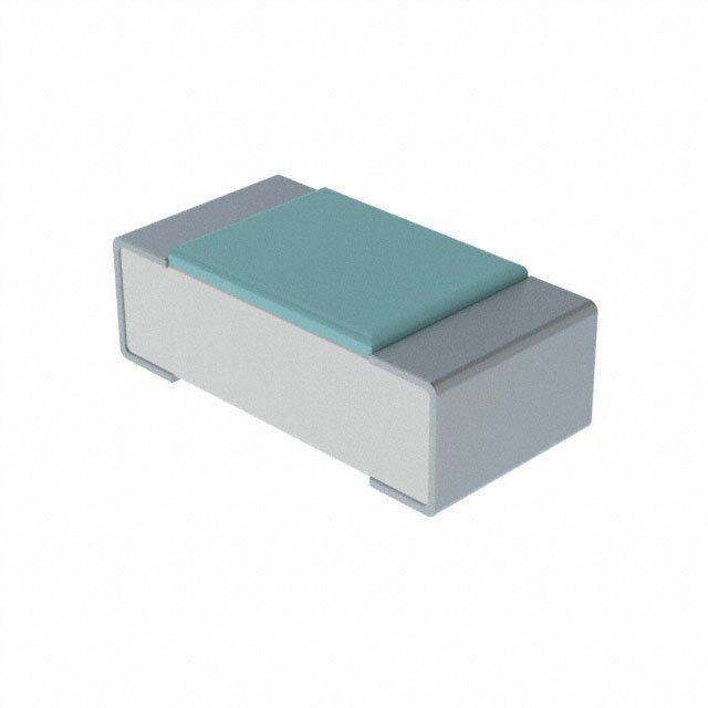
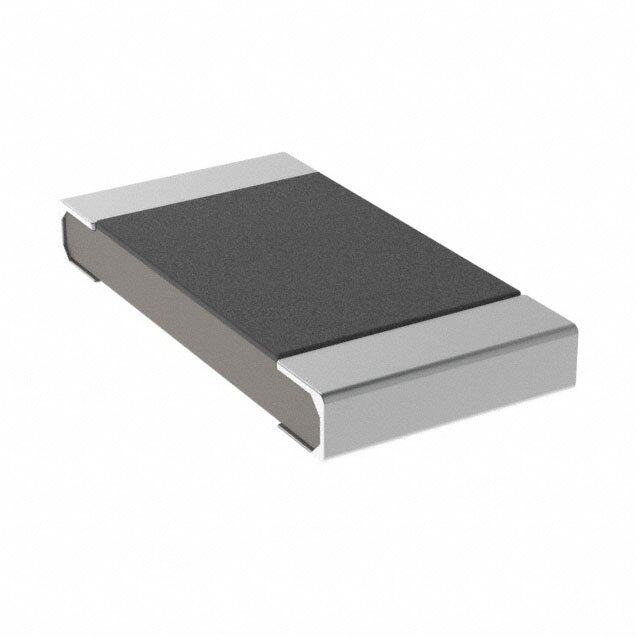
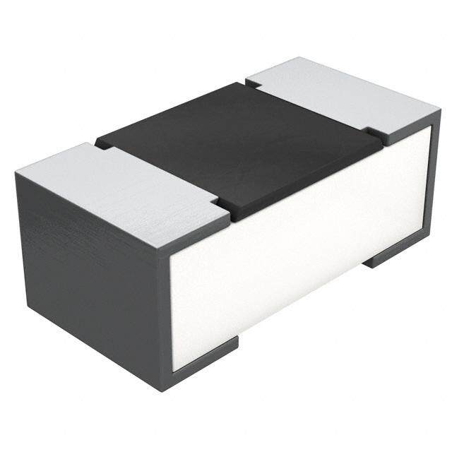
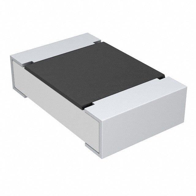
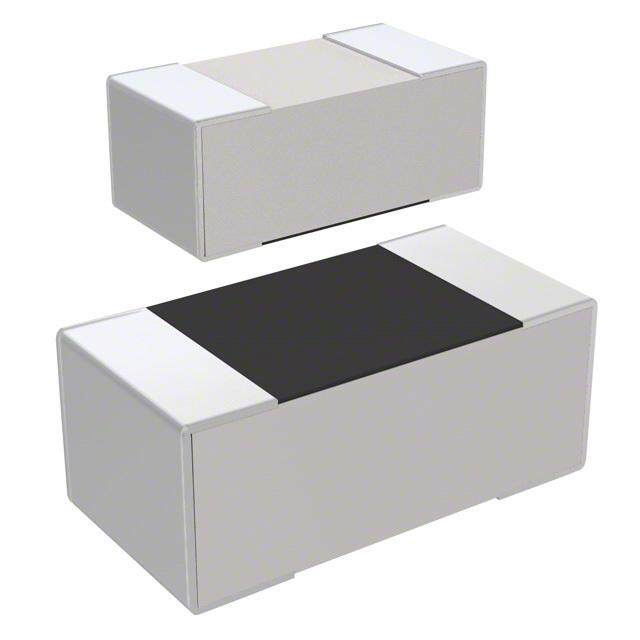
ICGOO电子元器件商城为您提供RK73H1JTTD2612F由KOA Speer设计生产,在icgoo商城现货销售,并且可以通过原厂、代理商等渠道进行代购。 RK73H1JTTD2612F价格参考¥0.01-¥0.01。KOA SpeerRK73H1JTTD2612F封装/规格:芯片电阻 - 表面安装, 26.1 kOhms ±1% 0.1W,1/10W 厚膜 芯片电阻 0603(1608 公制) 汽车级 AEC-Q200 厚膜。您可以下载RK73H1JTTD2612F参考资料、Datasheet数据手册功能说明书,资料中有RK73H1JTTD2612F 详细功能的应用电路图电压和使用方法及教程。
RK73H1JTTD2612F 是 KOA Speer Electronics, Inc. 生产的一款高精度表面贴装芯片电阻,具备高稳定性与可靠性,适用于对性能要求较高的电子设备和系统中。

该型号电阻的典型应用场景包括:

1. 工业控制设备:如PLC(可编程逻辑控制器)、传感器模块、工业自动化系统等,适用于高精度信号处理和电源管理。

2. 通信设备:用于基站、光模块、路由器和交换机等通信基础设施中,支持稳定的信号传输和处理。

3. 测试与测量仪器:如万用表、示波器、信号发生器等,RK73H1JTTD2612F 的高精度和低温度系数可确保测量结果的准确性。

4. 汽车电子系统:包括车载控制单元(ECU)、传感器模块、车载通信系统等,满足汽车环境对稳定性和可靠性的高要求。

5. 医疗设备:如诊断仪器、监测设备和便携式医疗设备,适用于对精度和长期稳定性有严格要求的应用场合。

6. 消费类电子产品:如高端音视频设备、智能家电等,用于关键信号路径或电源管理部分,确保系统稳定运行。

综上所述,RK73H1JTTD2612F 适用于需要高精度、高稳定性和高可靠性的多种高端电子应用领域。
| 参数 | 数值 |
| 品牌 | KOA Speer |
| 产品目录 | 无源元件 |
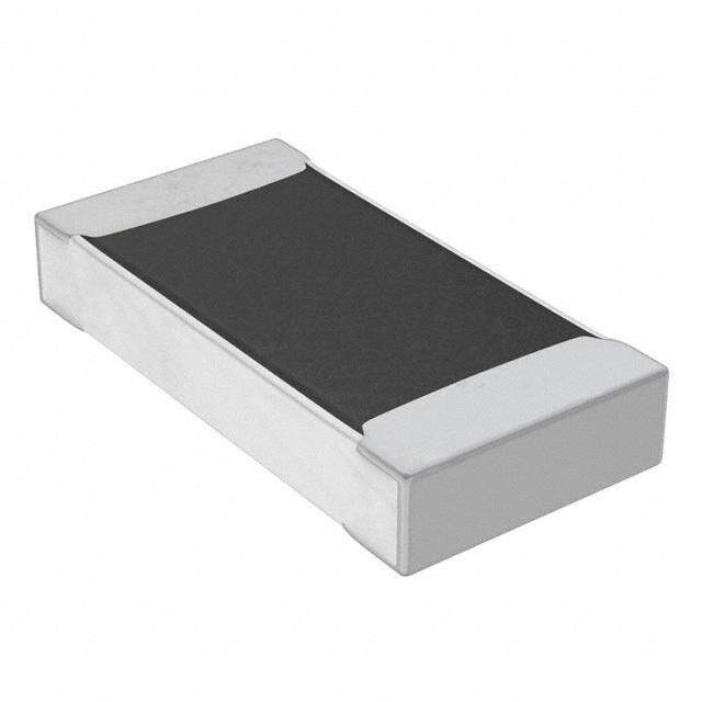
| 描述 | 厚膜电阻器 - SMD 1/10watts 26.1Kohms |
| 产品分类 | |
| 产品手册 | |
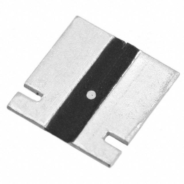
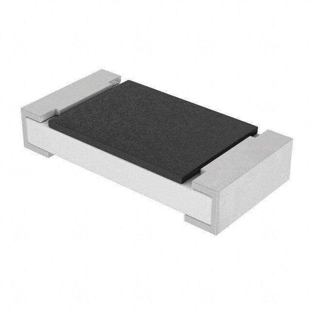
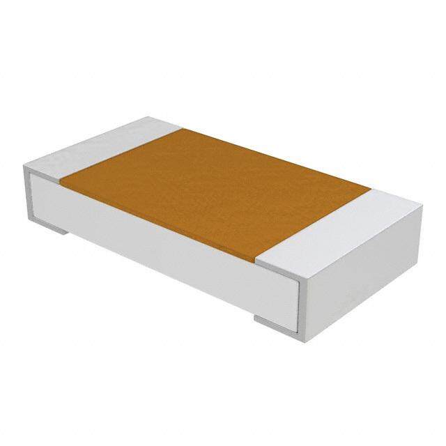
| 产品图片 |
|
| rohs | RoHS 合规性豁免 |
| 产品系列 | 薄膜电阻器,厚膜电阻器 - SMD,KOA Speer RK73H1JTTD2612F |
| 产品型号 | RK73H1JTTD2612F |
| 产品 | Thick Film Resistors SMD |
| 产品种类 | 厚膜电阻器 - SMD |
| 功率额定值 | 100 mW |
| 商标 | KOA Speer |
| 外壳代码-in | 0603 |
| 外壳代码-mm | 1608 |
| 外壳宽度 | 0.8 mm |
| 外壳长度 | 1.6 mm |
| 外壳高度 | 0.45 mm |
| 容差 | 1 % |
| 封装 | Reel |
| 封装/箱体 | 0603 (1608 metric) |
| 工作温度范围 | - 55 C to + 155 C |
| 工厂包装数量 | 5000 |
| 温度系数 | 100 PPM / C |
| 电压额定值 | 50 V |
| 电阻 | 26.1 kOhms |
| 系列 | RK73H |


- 商务部:美国ITC正式对集成电路等产品启动337调查
- 曝三星4nm工艺存在良率问题 高通将骁龙8 Gen1或转产台积电
- 太阳诱电将投资9.5亿元在常州建新厂生产MLCC 预计2023年完工
- 英特尔发布欧洲新工厂建设计划 深化IDM 2.0 战略
- 台积电先进制程称霸业界 有大客户加持明年业绩稳了
- 达到5530亿美元!SIA预计今年全球半导体销售额将创下新高
- 英特尔拟将自动驾驶子公司Mobileye上市 估值或超500亿美元
- 三星加码芯片和SET,合并消费电子和移动部门,撤换高东真等 CEO
- 三星电子宣布重大人事变动 还合并消费电子和移动部门
- 海关总署:前11个月进口集成电路产品价值2.52万亿元 增长14.8%


PDF Datasheet 数据手册内容提取
RK73H s r precision 0.5%, 1% tolerance o t thick film chip resistor s si e EU r features • Products with lead-free terminations meet EU RoHS requirements. EU RoHS regulation is not intended for Pb-glass contained in electrode, resistor element and glass. • AEC-Q200 Qualified: 0201 (1H), 0402 (1E), 0603 (1J), 0805 (2A), 1206 (2B), 1210 (2E), 2010 (2H/W2H), 2512 (3A/W3A/W3A2) Type* Dimensions inches (mm) dimensions (Inch Size Code) L W c d t and construction 1F .016±.0008.008±.0008 .004±.001 .004±.001 .005±.0008 (01005) (0.4±0.02) (0.2±0.02) (0.1±0.03) (0.11±0.03) (0.13±0.02) L c c 1H .024±.001 .012±.001 .004±.002 .006±.002 .009±.001 (0201) (0.6±0.03) (0.3±0.03) (0.1±0.05) (0.15±0.05) (0.23±0.03) W Solder 1E .039 +-..000042 .02±.002 .008±.004 .01 +-..000024 .014±.002 Plating (0402) (1.0 +0.1 ) (0.5±0.05) (0.2±0.1) (0.25 +0.05) (0.35±0.05) t Ni -0.05 -0.1 Plating 1J .063±.008 .031±.004 .012±.004 .012±.004 .018±.004 d Protective Resistive Inner (0603) (1.6±0.2) (0.8±0.1) (0.3±0.1) (0.3±0.1) (0.45±0.1) Coating Film Electrode Ceramic 2A .079±.008 .049±.004 .016±.008 .012 +-..000084 .02±.004 Derating CurveSubstrate (0805) (2.0±0.2) (1.25±0.1) (0.4±0.2) (0.3 +0.2) (0.5±0.1) -0.1 100 100 2B .063±.008 (1206) .126±.008 (1.6±0.2) 80 80 4600 1F 1 E , 31AH3,, A W1, J2W, H22,AH W,, 23WBA3, A2E, 2H, % Rated Power4600 1H, 1EW, 12JH, ,2 WA,3 2ABW (,1 32WAE2), (1222HE10) (3.2±0.2) .1(20.26±±.00.20)8 .(001.46 ++--00..00..1200)84 20 20 (2010) .197±.008 .098±.008 .02±.012 .024±.004 00 20 40 60 80 100 120 140 160 180 -060 -40 -20 0 20 40 60 80 100120 140 160 W2H (5.0±0.2) (2.5±0.2) (0.5±0.3) .026±.006 (0.6±0.1) Am7b0ient Temperatur1e25 155 -55 Terminal Part Temperatu9r5e 125 155 (2010) (0.65±0.15) (°C) (°C) For resistors operated at an ambient For resistors operated at a terminal part 3A .016 +-..000084 trweaimttihnp gteh sreah taaublrl eob veoe f dd7ee0rr°aaCteti ndog ri nac buaorcvvceeo.,r daa pnocweer taaebcmcoopvreed ,ra aant ucpreoe w woeift rhd r eathstiecnr gaib bseohdva eflol rdb eeer adacethinr agsti ezcdeu riovnre. W3(A25/W123)A2 .2(64.83±±.00.20)8 .1(32.21±±.00.20)8 .0(02.64± +-.000..120)6 Please refer to “Introduction of the derating (2512) (0.65±0.15) curve based on the terminal part temperature” in the beginning of our catalog before use. * Parentheses indicate EIA package size codes. ordering information RK73H 2B T TD 1003 F Termination Nominal Type Size Packaging Tolerance Material Resistance 1F T: Sn TX: 01005 only: 4mm width - 1mm pitch plastic embossed 3 significant D:±0.5% 1H (1F ~ W3A2) TBL: 01005 only: 2mm pitch pressed paper figures + 1 F: ±1% 1E Contact factory TC: 0201 only: 7" 2mm pitch pressed paper multiplier 1J for below (TC: 10,000 pcs/reel, TCM: 15,000 pcs/reel) “R” indicates options: TCD: 0201 only: 10" 2mm pitch pressed paper decimal on 2A TPD: 0402 only: 10" 2mm pitch plastic embossed L: SnPb value <100Ω 2B (1E, 1J, 2A, 2B, TPL: 0402 only: 2mm pitch punch paper 2E 2E, 2H, 3A) TP: 0402, 0603, 0805: 7" 2mm pitch punch paper TD: 0603, 0805, 1206, 1210: W2H G: Au 7" 4mm pitch punched paper W3A (1E ~ 2A: TDD: 0603, 0805, 1206, 1210: 10" paper tape 2H 10Ω ~ 1MΩ) TE: 0805, 1206, 1210, 2010 & 2512: 7" embossed plastic 3A TED:0805, 1206, 1210, 2010 & 2512: 10" embossed plastic W3A2 For further information on packaging, please refer to Appendix A Specifications given herein may be changed at any time without prior notice. Please confirm technical specifications before you order and/or use. 2/04/19 17 KOA Speer Electronics, Inc. • 199 Bolivar Drive • Bradford, PA 16701 • USA • 814-362-5536 • Fax: 814-362-8883 • www.koaspeer.com
RK73H r e s precision 0.5%, 1% tolerance is thick film chip resistor t o applications and ratings r s Rated Rated Resistance Range Maximum Maximum Operating Part Power Terminal T.C.R. Ambient Working Overload Temperature Designation Rating Part (x10-6/K) D±0.5% F±1% Temp. Temp. E-24, E-96 E-24, E-96* Voltage Voltage Range RK73H1F 0.03W — ±200 — 100kΩ - 2MΩ* 20V 30V -55°C to (01005) ±250 — 10Ω - 91kΩ* +125°C RK73H1H ±200 10Ω - 1MΩ 10Ω - 10MΩ* 0.05W 25V 50V (0201) ±400 — 1.0Ω - 9.1Ω* ±100 10Ω - 1MΩ 10Ω - 1MΩ RK73H1E (0402) 0.1W ±200 — 1.0Ω - 9.76Ω 75V 1.02MΩ - 10MΩ ±100 1.02kΩ - 1MΩ 1.02kΩ - 1MΩ 100V 0.1W RK73H1J ±200 — 1.02MΩ - 10MΩ 75V (0603) ±100 10Ω - 1kΩ 10Ω - 1kΩ 0.125W ±200 — 1.0Ω - 9.76Ω ±100 10Ω - 1MΩ 10Ω - 1MΩ RK73H2A 0.25W ±200 — 1.0Ω - 9.76Ω 150V 200V (0805) 70°C ±400 — 1.02MΩ - 10MΩ 125°C ±100 10Ω - 1MΩ 10Ω - 1MΩ RK73H2B 1.0Ω - 9.76Ω (1206) 0.25W ±200 — 1.02MΩ - 5.6MΩ -55°C to +155°C ±400 — 5.62MΩ - 10MΩ ±100 10Ω - 1MΩ 10Ω - 1MΩ RK73H2E — 1.0Ω - 9.76Ω (1210) 0.5W ±200 — 1.02MΩ - 5.6MΩ 200V 400V ±400 — 5.62MΩ - 10MΩ ±100 10Ω - 1MΩ 10Ω - 1MΩ RK73HW2H/2H 1.0Ω - 9.76Ω 0.75W ±200 — (2010) 1.02MΩ - 5.6MΩ ±400 — 5.62MΩ - 10MΩ ±100 10Ω - 1MΩ 10Ω - 1MΩ RK73HW3A/3A 1.0Ω - 9.76Ω 1.0W ±200 — 200V 400V (2512) 1.02MΩ - 5.6MΩ ±400 — 5.62MΩ - 10MΩ ±100 10Ω - 1MΩ 10Ω - 1MΩ RK73HW3A2 2.0W –– 95°C ±200 — 1.0Ω - 9.76Ω 200V 400V (2512) 1.02MΩ - 5.6MΩ ±400 — 5.62MΩ - 10MΩ Rated voltage = √Power rating x resistance value or max. working voltage, *1F:E-24. 1H: 1.0~9.1, 1M~10MΩ: E-24. If any questions arise whether to use the “Rated whichever is lower Ambient Temperature” or the “Rated Terminal Part Temperature,” please give priority to the “Rated Terminal Part Temperature.” Prior to use and for more details refer to “Introduction of the derating curves based on the terminal part temperature” in the beginning of the catalog. environmental applications While using under high power, the temperature of the product may increase depending on the condition of heat dissipation from PCB. Be sure to check the terminal part temperature Performance Characteristics as well as precautions to use on delivery specification before use. Requirement ∆ R (%+0.1 ) Ω Parameter Limit Typical Test Method Resistance Within specified tolerance — 25°C T.C.R. Within specified T.C.R. — +25°C/-55°C and +25°C/+125°C ±1%: 1F Rated Voltage x 2.5 for 5 seconds Overload (Short time) ±2% ±0.5% Another (1E, 2B, W3A2: Rated Voltage x 2 for 5 seconds) ±1%: 1F ~ W3A2 ±0.5%: 1F ~ W3A2 Resistance to Soldering Heat (10Ω≤R≤1MΩ); ±3%: 1H ~ (10Ω<R<1MΩ);±1%: 1H ~ 260°C ± 5°C, 10 seconds ± 1 second W3A2 (R<10Ω, R>1MΩ) W3A2 (R<10Ω, R>1MΩ) Rapid Change of Temperature ±1%: 1F; ±0.5% Another ±0.5%: 1F; ±0.3% Another -55°C (30 minutes), +125°C (30 minutes), 100 cycles ±2%: 1J, 2A, 2B ±0.75%: 1J, 2A, 2B; 40°C ± 2°C, 90%-95% RH, 1000 hours, 1.5 hr ON, Moisture Resistance ±3%: Another ±1.5%:1F, ±1%: Another 0.5 hr OFF cycle Endurance at 70°C ±2%: 1J, 2A, 2B; ±3%: Another ±0.75%: 1J, 2A, 2B; ±1%: Another 70°C ± 2°C, 1000 hours, 1.5 hr ON, 0.5 hr OFF cycle ±0.5%: 1F +125°C, 1000 hours: 1F; +155°C, 1000 hours: 1E, 1H, High Temperature Exposure ±1% ±0.3%: Another 1J, 2A, 2B, 2E, 2H/W2H, 3A/W3A/W3A2 Specifications given herein may be changed at any time without prior notice. Please confirm technical specifications before you order and/or use. 2/04/19 18 KOA Speer Electronics, Inc. • 199 Bolivar Drive • Bradford, PA 16701 • USA • 814-362-5536 • Fax: 814-362-8883 • www.koaspeer.com