ICGOO在线商城 > Labels, Signs, Barriers, Identification > Accessories > QPI-5LZ-01
 Datasheet下载
- 型号: QPI-5LZ-01
- 制造商: Vicor
- 库位|库存: xxxx|xxxx
- 要求:
| 数量阶梯 | 香港交货 | 国内含税 |
| +xxxx | $xxxx | ¥xxxx |
查看当月历史价格
查看今年历史价格
QPI-5LZ-01产品简介:
ICGOO电子元器件商城为您提供QPI-5LZ-01由Vicor设计生产,在icgoo商城现货销售,并且可以通过原厂、代理商等渠道进行代购。 QPI-5LZ-01价格参考。VicorQPI-5LZ-01封装/规格:Accessories, 。您可以下载QPI-5LZ-01参考资料、Datasheet数据手册功能说明书,资料中有QPI-5LZ-01 详细功能的应用电路图电压和使用方法及教程。
Vicor Corporation的QPI-5LZ-01是一款专为高性能电源模块设计的配件,属于其Quick-Power Integration(QPI)系列,主要用于支持Vicor电源模块的快速原型开发与系统集成。该配件典型应用于需要高效、高密度供电的电子系统中。

QPI-5LZ-01作为评估和测试工具,常用于通信设备、数据中心服务器、工业自动化系统、测试与测量仪器以及航空航天和国防领域的电源管理设计。它可配合Vicor的DC-DC转换器模块使用,帮助工程师在研发阶段快速搭建和验证电源架构,简化从设计到部署的流程。

其主要功能包括提供稳定的电气连接、散热支持和机械固定,确保电源模块在高负载条件下可靠运行。同时,QPI-5LZ-01具备良好的热管理和电磁兼容性设计,适用于对能效和空间利用要求严苛的应用环境。

总之,QPI-5LZ-01广泛应用于需要快速开发、高效率和高功率密度电源解决方案的研发与测试场景,是Vicor客户在产品开发初期不可或缺的辅助工具。
| 参数 | 数值 |
| 产品目录 | |
| 描述 | EMI FILTER 24V 14A ACTIVE EMI |
| 产品分类 | |
| 品牌 | Vicor Corporation |
| 数据手册 | |
| 产品图片 |
|
| 产品型号 | QPI-5LZ-01 |
| rohs | 无铅 / 符合限制有害物质指令(RoHS)规范要求 |
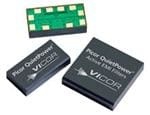
| 产品系列 | Picor® QuietPower® |
| 其它名称 | 1102-1099-5 |
| 标准包装 | 20 |
| 配件类型 | 输入 EMI 滤波器 |
| 配套使用产品/相关产品 | DC-DC 转换器 |


型号:EF-S1C
品牌:Panasonic Industrial Automation Sales
产品名称:Labels, Signs, Barriers, Identification
获取报价


- 商务部:美国ITC正式对集成电路等产品启动337调查
- 曝三星4nm工艺存在良率问题 高通将骁龙8 Gen1或转产台积电
- 太阳诱电将投资9.5亿元在常州建新厂生产MLCC 预计2023年完工
- 英特尔发布欧洲新工厂建设计划 深化IDM 2.0 战略
- 台积电先进制程称霸业界 有大客户加持明年业绩稳了
- 达到5530亿美元!SIA预计今年全球半导体销售额将创下新高
- 英特尔拟将自动驾驶子公司Mobileye上市 估值或超500亿美元
- 三星加码芯片和SET,合并消费电子和移动部门,撤换高东真等 CEO
- 三星电子宣布重大人事变动 还合并消费电子和移动部门
- 海关总署:前11个月进口集成电路产品价值2.52万亿元 增长14.8%


PDF Datasheet 数据手册内容提取
QPI-5 QUIETPOWER 14 A Active EMI Filter SIP for 24 Vdc Bus Description: Features: The QPI-5 active EMI filter attenuates conducted common- 60 dB CM attenuation at 250 KHz (50Ω) mode (CM) and differential-mode (DM) noise over the 75 dB DM attenuation at 250 KHz (50Ω) CISPR22 frequency range of 150 kHz to 30 MHz. The product 40 Vdc (max input) is designed for use on 24 Vdc bus (10 – 40 Vdc) systems, with 100 Vdc surge 100 ms 100 Vdc surge capability. The QPI-5’s 14 A rating supports 707 Vdc hipot hold off to shield plane multiple DC-DC converter loads up to an ambient 14 A rating temperature of 65°C without de-rating. Designed for the 25.3 x 25.3 x 5.2 mm Lidded SiP (System-in-Package) telecom and ITE bus range, the QPI-5 supports the PICMG® 24.9 x 24.9 x 4.4 mm Open-frame SiP 3.0 specification for filtering system boards to the EN55022 Low profile LGA package Class B limits. -40° to +125°C Ambient temperature (see Figure 10) Efficiency >99% In comparison to passive solutions, the use of active filtering Connect in series for higher attenuation reduces the volume of the common-mode choke, providing a TÜV Certified low profile, surface mount device. Smaller size saves valuable board real estate and the reduced height enhances airflow in blade applications. Applications The QPI-5 is available as a lidded or an open-frame SiP Industrial bus supplies (System-in-Package) with Telecom base stations LGA mounting. Evaluation IBA & distributed power boards are available to allow COTS systems for quick in-circuit testing of the QPI-5LZ within an Figure 1 - QPI-5LZ existing system design. (~1 in2 area) Typical Application: CIN Figure 2 – Typical QPI-5 application schematic with a Vicor brick converter. (1) Note 1: CB1 capacitor, referenced in all schematics, is a 47uF electrolytic; United Chemi-Con EMVE101ARA470MKE0S or equivalent. CY1 to CY4, referenced in all schematics, are 4.7nF hi-voltage safety capacitors; Vishay VY1472M63Y5UQ63V0 or equivalent. CIN is the manufacturer’s recommended value for input capacitor. Picor Corporation · picorpower.com QPI-5 Rev 2.9, Page 1 of 13
QPI-5 QUIETPOWER Absolute Maximum Ratings – Exceeding these parameters may result in permanent damage to the product. Input Voltage, BUS+ to BUS-, continuous -40 to 40 Vdc Input Voltage, BUS+ to BUS-, 100ms transient -100 to 100 Vdc BUS+/ BUS- to Shield pads, hi-pot -707 to 707 Vdc Input to output current, continuous @ 25°C T 14 Adc A Input to output current, 10 seconds @ 25°C T 20 Adc A Power dissipation, @ 65°C T , 14 A(2) 2.3 W A Operating temperature - T -40 to 125 °C A Thermal resistance(2) - R , using PCB layout in Figure 22 20 °C/W J-A Thermal resistance(2) - R 8 °C/W J-PCB Storage temperature, JEDEC Standard J-STD-033B -55 to 125 °C Reflow temperature, 20 s exposure 245 °C ESD, Human body model (HBM) -2000 to 2000 V Electrical Characteristics – Parameter limits apply over the operating temp. range, unless otherwise noted. Parameter Notes Min Typ Max Units BUS+ to BUS- input range Measured at 14 A, 65°C ambient temperature(2) 10 40 Vdc BUS+ to QPI+ voltage drop Measured at 14 A, 65°C ambient temperature(2) 135 mVdc BUS- to QPI- voltage drop Measured at 14 A, 65°C ambient temperature(2) 29 mVdc Common mode attenuation VBUS = 28 V, Frequency = 250 KHz, line impedance = 50Ω 60 dB Differential mode attenuation VBUS = 28 V, Frequency = 250 KHz, line impedance = 50Ω 75 dB Input bias current at 40 V Input current from BUS+ to BUS- 8 mA Note 2: See Figure 10 for the current de-rating curve. Pad Descriptions Pad Number Name Description LGA Pattern (Top View) 12, 13, 14 BUS+ Positive bus potential THERM2 THERM1 1, 15, 16 BUS- Negative bus potential 12 11 10 9 7, 8, 9 QPI+ Positive input to the converter 13 8 2, 3, 4 QPI- Negative input to the converter BUS+ QPI+ 5, 6 Shield Shield connects to the system chassis or to a safety ground. 14 7 10 THERM1 These pads are electrically isolated from the internal circuitry of 15 6 BUS- Shield the QPI-5. Either connecting THERM1 to QPI+ and THERM2 to 16 5 BUS+, or to copper region(s) not connected to Shield, is 11 THERM2 recommended to help with thermal management. 1 2 3 4 QPI- Ordering Information Part Number Description QPI-5LZ(3) QPI-5 LGA Package, RoHS Compliant QPI-5LZ-01 QPI-5 LGA Package, RoHS Compliant, Open Frame Package Note 3: QPI-5LZ is a non-hermetically sealed package. Please read the “Post Solder Cleaning” section on page 12. QPI-5 Evaluation Boards Part # Description: A QPI-5LZ mounted on a small evaluation board with screw terminal blocks to allow for easy connection into an QPI-5-EVAL1 existing system. A QPI-5LZ mounted on a carrier board designed for use with DOSA compliant footprint dc-dc converters. Screw QPI-5-CB1 terminal blocks to allow for easy connection into an existing system. Picor Corporation · picorpower.com QPI-5 Rev 2.9, Page 2 of 13
QPI-5 QUIETPOWER Applications Information EMI Sources Many of the components in today’s power conversion pass the EN55022 class B limits. modules are sources of high-frequency EMI noise generation. Diodes, high-frequency switching devices, transformers and The other component of the passive filter is the differential inductors, and circuit layouts passing high dv/dt or di/dt LC network. Again, the inductor is chosen such that it will signals are all potential sources of EMI. present a high-impedance in the differential EMI loop at the EMI’s base frequency. The differential capacitor will then EMI is propagated either by radiated or conductive means. shunt the EMI back to its source. The QPI-5 was specifically Radiated EMI can be sourced from these components as well designed to work with conventional switching frequency as by circuit loops that act like antennas and broadcast the converters like Vicor’s Brick products; Micro, Mini and Maxi noise signals to neighboring circuit paths. This also means modules; as well as converters from various vendors. that these loops can act as receivers of a broadcasted signal. This radiated EMI noise can be reduced by proper circuit Active EMI Filtering layout and by shielding potential sources of EMI transmission. PICOR’s QPI-5 active EMI filter uses the same basic principles for filtering as the passive approach, but its active common- There are two basic forms of conducted EMI that typically mode filter can perform as well as a passive filter, when need to be filtered; namely common-mode (CM) and filtering lower frequencies, in much less board area. differential-mode (DM) EMI. Differential-mode resides in the normal power loop of a power source and its load; where the signal travels from the source to the load and then returns to the source. Common-mode is a signal that travels through both leads of the source and is returned to earth via parasitic pathways, either capacitively or inductively coupled. Figure 8 to Figure 9 are the resulting EMI plots, after filtering by the QPI-5, of the total noise, both common and differential mode, of a Vicor Brick converter. These converters are mounted on a QPI-5 evaluation board and tested under various loads. The red and blue traces represent the positive and negative branches of total noise, as measured using an industry standard LISN setup, as is shown in Figures 6 and 7. Differential-mode EMI is typically larger in magnitude than Figure 3 – Simplified Active EMI filter circuit. common-mode, since common-mode is produced by the physical imbalances in the differential loop path. Reducing Typically, the lower the frequency the greater the needed differential EMI will cause a reduction in common-mode EMI. inductance would be to properly filter the EMI signal. This means either a larger core or a greater number of turns on a Passive EMI Filtering smaller core. A larger core requires more board space, where The basic premise of filtering EMI is to insert a high- a smaller core with more turns has a greater amount of impedance, at the EMI’s base frequency, in both the unwanted parasitics that can affect the filters ability to differential and common-mode paths as it returns to the attenuate EMI signals. power source. Figure 3 is a simplified schematic of the QPI-5’s active and Passive filters use common-mode chokes and “Y” capacitors passive circuitry used for EMI filtering. The QPI-5’s active to filter out common-mode EMI. These chokes are designed filter uses a small high-frequency common-mode transformer to present a high-impedance at the EMI frequency in series to filter the higher frequencies and adds a sensing element to with the return path, and a low impedance path to the earth it so that the lower frequency common mode signal can be signal via the “Y” caps. This network will force the EMI signals sensed and a correction signal can be generated and inserted to re-circulate within a confined area and not to propagate to into the shield connection. By this means, the QPI-5 is the outside world. Often two common-mode networks are capable of providing EMI filtering of converters in far less required to filter EMI within the frequency span required to space than standard passive filters and can provide filtering over the entire EN55022 class B range. Picor Corporation · picorpower.com QPI-5 Rev 2.9, Page 3 of 13
QPI-5 QUIETPOWER EMI Management The more effectively EMI is managed at the source, namely favor one topology versus another. The EMI generated by the power converter, the less EMI attenuation the filter will the “base-plate” configuration is much greater than that have to do. The addition of “Y” capacitors to the input and generated by the “open-frame”. Selecting the right topology output power nodes of the converter will help to limit the will greatly reduce the amount of EMI signal that needs to be amount of EMI that will propagate to the input source. filtered. Figure 2 shows the base-plate topology of re-circulating “Y” caps. Here, CY1 to CY4 are connected to each power node of the dc-dc converter, and then are commoned together on a copper shield plane created under the converter. The addition of the copper shield plane helps in the containment of the radiated EMI, converting it back to conducted EMI and shunting it back to its source. The RY resistor, connected between the shield plane and the QPI’s shield pin, provides an impedance that makes the QPI’s common mode noise cancelation signal more effective at removing the common mode noise that would normally return to the shield/earth connection. It is important when laying out the QPI that the RY resistor connects to the QPI’s shield pin before making the connection to earth ground. Figure 4 – An unfiltered converter’s response to “open-frame” (light blue) and “base-plate” (purple) EMI configurations. In Figure 5, the open-frame topology is shown where the “Y” capacitors (CY1 and CY2) re-circulate the EMI signals between There are two basic topologies for the connection of the re- the positive input and output, and the negative input and circulating “Y” capacitors, referred to as “open-frame” and output nodes of the power conversion stage. “base-plate”. Figure 4 illustrates how a converter can Figure 5 - Typical 'open-frame" application. Picor Corporation · picorpower.com QPI-5 Rev 2.9, Page 4 of 13
QPI-5 QUIETPOWER Attenuation Test Setups: Figure 6 - Open-frame EMI test setup using the QPI-5-CB1 carrier board with 24V converter. Figure 7 - Base-plate EMI test setup using the QPI-5-CB1 carrier board with 24V converter. In Figures 6 and 7, C1 is the required 47uF capacitor (United caps are 4.7nF ceramic (Murata GRM31BR73A472KW01L or Chemi-Con EMVE101ARA470MKE0S or equivalent), C2 is a equivalent). converter input cap (value dependant on converter), and CY Attenuation Plots: Total EMI noise in base-plate configuration, tested as shown in Figure 7. Figure 8 – V24B24C200BG using base-plate “Y” capacitors Figure 9 – V24B12C200BN using base-plate “Y” capacitors with a 171W load. with a 136W load. Picor Corporation · picorpower.com QPI-5 Rev 2.9, Page 5 of 13
QPI-5 QUIETPOWER Current De-Rating: mounted to QPI-5-EVAL1 evaluation board. 20 2.5 18 16 2.0 s) 14 att W ps) 12 1.5 n ( m o ent (A 10 ssipati m Curr 8 1.0 wer Di u o axim 6 um P M m 4 0.5 xi a M 2 0 0.0 -40 -15 10 35 60 85 110 QPI-5 Current QPI-5 Power Dissipation Ambient Temperature (°C) Figure 10 - Current de-rating and power dissipation over ambient temperature range. The de-rating curve in Figure 10 is based on the maximum resistance between the inputs and outputs of the filter. The allowable internal component temperature and the 14A internal resistance value is temperature compensated for the maximum rating of the QPI-5. The power dissipation curve is power dissipation curve. The left axis is in amps for the solid based on the current squared multiplied by the internal trace, the right axis is in watts for the dashed trace. Picor Corporation · picorpower.com QPI-5 Rev 2.9, Page 6 of 13
QPI-5 QUIETPOWER QPI Application Circuits: Filtering Dual Converters CIN1 CIN2 Figure 11 – The QPI-5 filtering dual supplies, using a single RY resistor. (4) The shield plane under the two converters in Figure 11 should separate RY resistor. be one contiguous plane under both. The circuit in Figure 11 is capable of filtering more converters than shown, up to the The QPI-5 is not designed to be used in parallel with another maximum current limit of the QPI-5. In Figure 12, a separate QPI-5 to achieve a higher current rating, but it can be used shield plane is required for each converter along with a multiple times within a system design. Filtering Parallel Converters CIN1 CIN2 Figure 12 – Dual QPI-5’s filtering paralleled converters feeding a common load. (4) Note 4: In Figures 11 and 12; CIN1 and CIN2, CY1 through CY8, should be the value and voltage rating recommended by the converter’s manufacturer. Picor Corporation · picorpower.com QPI-5 Rev 2.9, Page 7 of 13
QPI-5 QUIETPOWER Output to Chassis Connection Using the QPI-5 CIN Figure 13 – Connecting the converter’s output ground to chassis through an inductor. (5) Figure 14 -Total Noise V24B12C200BN with a 136W load, connected as shown in Figure 13 The direct connection of the converter’s output to the Figure 8, but uses an inductor in place of RY and has the earth/chassis will degrade the EMI attenuation performance of converter’s output ground connected to the shield plane. the QPI-5. Picor recommends that the connection to the earth be made through a series inductor, rated to the maximum The connection of the shield plane directly to the chassis/earth output current of the converter, as shown in Figure 13. The will also degrade EMI attenuation by the QPI-5 and is therefore EMI plot shown in Figure 14 is of the same converter as in not recommended. Note 5: In Figure 13; CIN, CY1 through CY3, should be the value and voltage rating recommended by the converter’s manufacturer. Picor Corporation · picorpower.com QPI-5 Rev 2.9, Page 8 of 13
QPI-5 QUIETPOWER QPI Insertion Loss Measurements 90 80 70 B] 60 QPI Insertion Loss Equation: n [d 50 o ati enu 40 Att 30 20 10 0 0.01 0.1 1 10 QPI-5 Common QPI-5 Differential Frequency [MHz] Figure 15 - Attenuation curves into a 50Ω line impedance, bias from a 28V bus. QPI Insertion Loss Test Circuits Figure 16 – Test Set-up to measure Differential Mode EMI currents in Figure 15. Figure 17 - Test Set-up to measure Common Mode EMI currents in Figure 15. Picor Corporation · picorpower.com QPI-5 Rev 2.9, Page 9 of 13
QPI-5 QUIETPOWER Mechanicals Figure 18 - Lidded Package Dimensions, tolerance of ±0.004” 0.006" [0.15mm] max. 0.006" [0.15mm] max. 0.260" [6.604 mm] 5LZ-01 0.275" [6.985 mm] 0.979" [24.867 mm] Pin 1 0.979" [24.867 mm] 0.174 [4.420 mm] Figure 19 - Open-frame Package dimensions, tolerance of ±0.004”. Pick and Place from label center. Picor Corporation · picorpower.com QPI-5 Rev 2.9, Page 10 of 13
QPI-5 QUIETPOWER Pad and Stencil Definitions: QPI-5 LGA QPI-5 PCB Pattern Receptor Pattern (Bottom View) (Top View) 0.996" (LID) 0.979" (OF) 0.441 0.441 0.300 0.300 0.100 0.100 00000.....000000000000000 0.979" (OF) 0.996" (LID) 0.000 0.100 0.100 0.300 0.300 0.441 0.441 1 0 0 00 0 0 1 1 0 0 0 0 0 1 4 0 0 00 0 0 4 4 0 0 0 0 0 4 4 3 1 00 1 3 4 4 3 1 0 1 3 4 0. 0. 0. 0.0. 0. 0. 0. 0. 0. 0. 0. 0. 0. 0. Figure 20 - Bottom view of open-frame (OF) and lidded (LID) products. (All dimensions are in inches.) 45.000° 0.145" 0.149" 0.129" 0.082" 0.085" 0.073" 0.041" 0.043" 0.037" 1 place 0.000" 0.000" 0.000" 0.082" 0.086" 0.073" 0.041" 0.043" 0.037" 13 places 0.000" 0.000" 0.000" R0.041 R0.043 R0.037 0.082" 0.086" 0.073" 0.041" 0.043" 0.037" 2 places 0.000" 0.000" 0.000" 0.1250" 0.129" 0.112" LGA Pad Detail: Receiving Pad Detail: Stencil Detail: Figure 21 - Recommended receptor and stencil patterns. (All dimensions are in inches.) Stencil definition is based on a 6mil stencil thickness, 80% of LGA pad area coverage. LGA Package dimensions are for both the Open- Frame and Lidded versions of the QPI-5. Picor Corporation · picorpower.com QPI-5 Rev 2.9, Page 11 of 13
QPI-5 QUIETPOWER QPI-5 PCB Layout Recommendations: Figure 22 - 3D view of paralleling planes underneath the QPI-5. PCB Layout Post Solder Cleaning When laying out the QPI-5 EMI filter it is important for the Picor’s LZ version QP SIPs are not hermetically sealed and designer to be aware of the radiated EMI field that all must not be exposed to liquid, including but not limited to converters emit and to place the QPI-5 outside of this field cleaning solvents, aqueous washing solutions or pressurized area. It is also recommended that the bus lines feeding into sprays. When soldering, it is recommended that no-clean flux the QPI filter are not routed such that they lie between the solder be used, as this will ensure that potentially corrosive QPI and the converter, or that their copper planes over-lap on mobile ions will not remain on, around, or under the module inner layers. This can cause EMI noise to be coupled from following the soldering process. For applications where the input to output via the parasitic capacitance between the end product must be cleaned in a liquid solvent, Picor planes. recommends using the QPI-5LZ-01, open-frame version of the EMI filter. In Figure 22, the QPI-5 is located ~1.5 inches from the converter’s input pins, and the BUS voltage pins are located on the side farthest away from the converter, to keep the radiated EMI from by-passing the filter and coupling directly to the BUS feeds. QPI-5 Mechanical Data Datum Units QPI-5LZ QPI-5LZ-01 Notes FITS Failure/Billion Hrs. 208 208 FITS based on the BellCore Standard TR-332 MTBF Million Hrs. 4.81 4.81 MTBFs based on the BellCore Standard TR-332 Weight grams 5.4 3.1 MSL 3 3 Peak reflow °C/20 seconds 245 245 IPC/JEDEC J-STD-020D Temperature Picor Corporation · picorpower.com QPI-5 Rev 2.9, Page 12 of 13
QPI-5 QUIETPOWER Warranty Vicor products are guaranteed for two years from date of shipment against defects in material or workmanship when in normal use and service. This warranty does not extend to products subjected to misuse, accident, or improper application or maintenance. Vicor shall not be liable for collateral or consequential damage. This warranty is extended to the original purchaser only. EXCEPT FOR THE FOREGOING EXPRESS WARRANTY, VICOR MAKES NO WARRANTY, EXPRESS OR LIMITED, INCLUDING, BUT NOT LIMITED TO, THE WARRANTY OF MERCHANTABILITY OR FITNESS FOR A PARTICULAR PURPOSE. Vicor will repair or replace defective products in accordance with its own best judgment. For service under this warranty, the buyer must contact Vicor to obtain a Return Material Authorization (RMA) number and shipping instructions. Products returned without prior authorization will be returned to the buyer. The buyer will pay all charges incurred in returning the product to the factory. Vicor will pay all reshipment charges if the product was defective within the terms of this warranty. Information published by Vicor has been carefully checked and is believed to be accurate; however, no responsibility is assumed for inaccuracies. Vicor reserves the right to make changes to any products without further notice to improve reliability, function, or design. Vicor does not assume any liability arising out of the application or use of any product or circuit; neither does it convey any license under its patent rights nor the rights of others. Vicor general policy does not recommend the use of its components in life support applications wherein a failure or malfunction may directly threaten life or injury. Per Vicor Terms and Conditions of Sale, the user of Vicor components in life support applications assumes all risks of such use and indemnifies Vicor against all damages. Vicor’s comprehensive line of power solutions includes high density AC-DC and DC-DC modules and accessory components, fully configurable AC-DC and DC-DC power supplies, and complete custom power systems. Information furnished by Vicor is believed to be accurate and reliable. However, no responsibility is assumed by Vicor for its use. Vicor components are not designed to be used in applications, such as life support systems, wherein a failure or malfunction could result in injury or death. All sales are subject to Vicor’s Terms and Conditions of Sale, which are available upon request. Specifications are subject to change without notice. Vicor Corporation Picor Corporation 25 Frontage Road 51 Industrial Drive Andover, MA 01810 North Smithfield, RI 02896 USA USA Customer Service: custserv@vicorpower.com Technical Support: apps@vicorpower.com Tel: 800-735-6200 Fax: 978-475-6715 Picor Corporation · picorpower.com QPI-5 Rev 2.9, Page 13 of 13
Mouser Electronics Authorized Distributor Click to View Pricing, Inventory, Delivery & Lifecycle Information: V icor: QPI-5LZ-01 QPI-5-CB1 QPI-5LZ